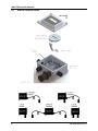
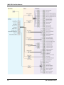
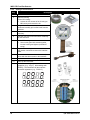
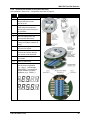
1
Fixed Gas Detector
User Manual
Installation ● Operation ● Configuration ● Troubleshooting
P/N: 1100-1000
August 21, 2015
Version 0
Product Leadership • Training • Service • Reliability
MGS-550 Fixed Gas Detector
WARRANTY POLICY
Bacharach, Inc. warrants this instrument, excluding sensors, to be free from defects in materials and workmanship for a period of
two years from the date of purchase by the original owner. The sensors have a pro-rated warranty period of 6 to 18 months,
depending on the sensor type. If the product should become defective within this warranty period, we will repair or replace it at our
discretion.
The warranty status may be affected if the instrument has not been used and maintained per the instructions in this manual or has
been abused, damaged, or modified in any way. This instrument is only to be used for purposes stated herein. The manufacturer is
not liable for auxiliary interfaced equipment or consequential damage.
Due to ongoing research, development, and product testing, the manufacturer reserves the right to change specifications without
notice. The information contained herein is based on data considered accurate. However, no warranty is expressed or implied
regarding the accuracy of this data.
All goods must be shipped to the manufacturer by prepaid freight. All returned goods must be pre-authorized by obtaining a return
merchandise authorization (RMA) number. Contact the manufacturer for a number and procedures required for product transport.
SERVICE POLICY
Bacharach, Inc. maintains an instrument service facility at the factory. Some Bacharach distributors/agents may also have repair
facilities; however, Bacharach assumes no liability for service performed by anyone other than Bacharach personnel. Repairs are
warranted for 90 days after date of shipment (sensors, pumps, filters and batteries have individual warranties). Should your
instrument require non-warranty repair, you may contact the distributor from whom it was purchased or you may contact Bacharach
directly.
If Bacharach is to do the repair work, send the instrument, prepaid, to the closest Service Center.
Service Location
Service Contact Information
Service Shipping Address
United States
http://mybacharach.com/rmaform/
Phone:
+1 724 334 5000
Toll Free:
1 800 736 4666
Fax:
+1 724 334 5001
Email:
[email protected]
Bacharach, Inc.
621 Hunt Valley Circle
New Kensington, PA 15068, USA
ATTN: Service Department
Phone:
Fax:
Email:
+353 1 284 6388
+353 1 284 6389
[email protected]
Murco – A Bacharach Company
114A Georges Street Lower
Dun Laoghaire, Dublin, Ireland
ATTN: Service Department
Phone:
Fax:
Email:
+1 905 470 8985
+1 905 470 8963
[email protected]
Ireland
Canada
Bacharach of Canada
20 Amber Street Unit #7
Markham, Ontario L3R 5P4, Canada
ATTN: Service Department
Always include your RMA #, address, telephone number, contact name, shipping/billing information and a description of the defect
as you perceive it. You will be contacted with a cost estimate for expected repairs prior to the performance of any service work. For
liability reasons, Bacharach has a policy of performing all needed repairs to restore the instrument to full operating condition.
Prior to shipping equipment to Bacharach, contact our office for an RMA # (returned merchandise authorization). All returned goods
must be accompanied with an RMA number.
Pack the equipment well (in its original packing if possible), as Bacharach cannot be held responsible for any damage incurred
during shipping to our facility.
NOTICES
This manual is subject to copyright protection; all rights are reserved under international and domestic copyright laws. This manual
may not be copied or translated, in whole or in part, in any manner or format, without the written permission of Bacharach, Inc.
All software utilized and/or distributed by Bacharach is subject to copyright protection. All rights are reserved. No party may use or
copy such software in any manner or format, except to the extent that Bacharach grants them a license to do so. If this software is
being loaded onto more than one computer, extra software licenses must be purchased.
2
P/N: 1100-1000 Version 0
MGS-550 Fixed Gas Detector
TABLE OF CONTENTS
SECTION 1.
SAFETY ............................................................................................................................ 5
1.1 Definition of Alert Icons .............................................................................................................. 5
1.2 General Safety Statements ....................................................................................................... 5
1.3 Safe Connection of Electrical Devices ...................................................................................... 5
SECTION 2.
DESCRIPTION .................................................................................................................. 6
2.1 Product Overview ...................................................................................................................... 6
2.2 Key Product Features ................................................................................................................ 7
2.3 General Purpose Option ............................................................................................................ 8
2.4 Explosion Proof Option .............................................................................................................. 9
2.5 Sensor Styles........................................................................................................................... 10
SECTION 3.
INSTALLATION .............................................................................................................. 11
3.1 General Information for Installation ......................................................................................... 11
3.2 Installation Restrictions ............................................................................................................ 11
3.3 Mechanical Installation ............................................................................................................ 12
3.4 Electrical Installation ................................................................................................................ 12
3.4.1 Preparations ............................................................................................................... 12
3.4.2 Power and Signal Wiring ............................................................................................ 14
3.4.3 Relay Wiring ............................................................................................................... 15
3.4.4 Installation of Remote Sensing Head ......................................................................... 16
3.4.5 Connecting One or More MGS-550s to a Bacharach Controller ................................ 17
3.4.6 Modbus RTU Interface ............................................................................................... 17
3.4.7 Conclusion .................................................................................................................. 17
SECTION 4.
OPERATION ................................................................................................................... 18
4.1 Overview of Normal Operation ................................................................................................ 18
4.1.1 Applying Power and the Start-up Sequence .............................................................. 18
4.1.2 Verifying Analog Signals............................................................................................. 19
4.1.3 Verifying the Digital Modbus Signal ............................................................................ 19
4.1.4 The 5-Digit Display and LEDs .................................................................................... 19
4.2 Menus ...................................................................................................................................... 21
4.2.1 General Navigation ..................................................................................................... 21
4.2.2 Checking Status and Changing Parameter Values .................................................... 22
4.2.3 Exiting the Menu ......................................................................................................... 22
4.2.4 Menu Overview ........................................................................................................... 23
4.3 Functions ................................................................................................................................. 25
4.3.1 Offline Mode (F-01) .................................................................................................... 25
4.3.2 Zero Adjustment (F-02) .............................................................................................. 25
4.3.3 Span Adjustment (F-03) ............................................................................................. 25
4.3.4 Instrument Test (F-04) ................................................................................................ 25
4.3.5 Parameter Menu (F-05) .............................................................................................. 26
4.3.6 Register Sensor (F-06) ............................................................................................... 26
4.3.7 De-register One Sensor (F-07) ................................................................................... 27
4.3.8 De-register All Sensors and Reset Node Address (F-08) .......................................... 27
4.3.9 Diagnostics, System Information and Fault Data (F-09) ............................................ 28
4.3.10 Reset System to Factory Default Setting (F-10) ........................................................ 28
4.4 Parameters .............................................................................................................................. 29
4.4.1 Sensor 1 Settings (S1-xx) and Sensor 2 Settings (S2-xx) if Connected .................... 29
4.4.2 Relay Designation (RX-xx) ......................................................................................... 32
4.4.3 Alarm Configuration (AF-xx) ....................................................................................... 33
4.4.4 Analog Output Configuration (AX-xx) ......................................................................... 34
4.4.5 Modbus Configuration (MB-xx) ................................................................................... 35
4.4.6 Display Mode (P1-01) ................................................................................................. 35
4.4.7 Buzzer Designation (B1-xx) ........................................................................................ 35
SECTION 5.
MAINTENANCE .............................................................................................................. 36
5.1 Maintenance Intervals ............................................................................................................. 36
P/N: 1100-1000 Version 0
3
MGS-550 Fixed Gas Detector
5.2
5.3
5.4
5.5
5.6
5.7
5.8
Making Adjustments to Sensors .............................................................................................. 36
5.2.1 Introduction ................................................................................................................. 36
5.2.2 General Procedure ..................................................................................................... 37
5.2.3 Zero Adjustment ......................................................................................................... 38
5.2.4 Span Adjustment ........................................................................................................ 38
5.2.5 System Bump Test ..................................................................................................... 38
Troubleshooting ....................................................................................................................... 39
5.3.1 Hexadecimal Format .................................................................................................. 39
5.3.2 Diagnostics Attributes ................................................................................................. 39
5.3.3 Instrument Electronics Critical (E100) Faults ............................................................. 41
5.3.4 Non-Critical (E300) Faults .......................................................................................... 42
5.3.5 Sensor Faults ............................................................................................................. 42
Sensor Maintenance (General Purpose Housings) ................................................................. 44
5.4.1 Components Overview ............................................................................................... 44
5.4.2 Replacing the Sensor Module .................................................................................... 45
5.4.3 Replacing the Sensor Control Board .......................................................................... 46
5.4.4 Replacing the Local Sensing Head Assembly............................................................ 47
5.4.5 Adding a Second Sensor ............................................................................................ 48
5.4.6 Replacing the Remote Sensing Head Assembly ....................................................... 49
Sensor Maintenance (Explosion Proof Housings) ................................................................... 50
5.5.1 Components Overview ............................................................................................... 50
5.5.2 Replacing the Sensor Module .................................................................................... 51
5.5.3 Replacing the Sensor Control Board .......................................................................... 52
5.5.4 Replacing the Local Sensing Head Assembly............................................................ 53
5.5.5 Replacing the Remote Sensing Head Assembly ....................................................... 54
Replacing the Instrument Electronics ...................................................................................... 55
Replacing the Interface Board ................................................................................................. 56
Cleaning the Instrument .......................................................................................................... 56
SECTION 6.
FACTORY DEFAULT SETTINGS .................................................................................. 57
SECTION 7.
SENSOR PRINCIPLE ..................................................................................................... 59
7.1 Electrochemical Sensors ......................................................................................................... 59
7.2 Catalytic Bead Sensors ........................................................................................................... 59
7.3 Semiconductor Sensors .......................................................................................................... 59
7.4 Infrared Sensors ...................................................................................................................... 60
SECTION 8.
DISPOSING OF THE INSTRUMENT ............................................................................. 61
8.1 Disposing of Electrical and Electronic Equipment ................................................................... 61
8.2 Disposing of Electrochemical Sensors .................................................................................... 61
SECTION 9.
TECHNICAL DATA......................................................................................................... 62
9.1 General Specifications ............................................................................................................. 62
9.2 Sensor Specifications .............................................................................................................. 63
9.3 Modbus Registers .................................................................................................................... 64
9.3.1 Analog Input Registers ............................................................................................... 65
9.3.2 Analog Output Registers ............................................................................................ 67
9.3.3 Input Status Flags ....................................................................................................... 69
9.3.4 Output Status Flags .................................................................................................... 70
SECTION 10.
ORDERING INFORMATION .......................................................................................... 72
10.1 MGS-550 Instrument Only ....................................................................................................... 72
10.2 MGS-550 Gas Detector, IP66 with IP66 Sensor ..................................................................... 72
10.3 MGS-550 Ex d Instruments with Sensing Heads .................................................................... 74
10.4 MGS-550 Gas Detector, Ex d Enclosure with Ex d Sensing Head ......................................... 74
10.5 MGS-550 5m Remote and Second Sensing Heads ................................................................ 76
10.6 MGS-550 Replacement Parts and Accessories ...................................................................... 78
SECTION 11.
4
DECLARATION OF CONFORMITY ............................................................................... 79
P/N: 1100-1000 Version 0
MGS-550 Fixed Gas Detector
SECTION 1.
1.1
SAFETY
Definition of Alert Icons
The following alert icons are used in this document to highlight areas of the associated text that require a
greater awareness by the user.
Alert
Icon
Description
DANGER
Indicates an imminently hazardous situation which, if not avoided, will
result in death or serious injury.
WARNING
Indicates a potentially hazardous situation which, if not avoided, could
result in death or serious injury.
CAUTION
Indicates a potentially hazardous situation which, if not avoided, could
result in physical injury or damage to the product or environment. It may
also be used to alert against unsafe practices.
NOTICE
1.2
General Safety Statements
•
•
•
•
•
•
•
•
1.3
Indicates additional information on how to use the product.
Before using this product, carefully read and strictly follow the instructions in the manual.
Use the product only for the purposes specified in this document and under the conditions
listed.
Ensure that product documentation is retained, made available, and appropriately used by
anyone operating the product.
Comply with all local and national laws, rules, and regulations associated with this product.
Only trained and competent personnel may use this product.
Only trained and competent personnel may inspect, repair and maintain the product as
detailed in this manual. Maintenance that is not detailed in this manual must be completed by
Bacharach or personnel qualified by Bacharach.
Use only genuine Bacharach spare parts and accessories. Otherwise, operation may be
impaired.
Only operate the product within the framework of a risk-based alarm signaling concept.
Safe Connection of Electrical Devices
•
Before connecting this instrument to electrical devices not mentioned in this manual, consult
the manufacturer or a qualified professional.
P/N: 1100-1000 Version 0
5
MGS-550 Fixed Gas Detector
SECTION 2.
2.1
DESCRIPTION
Product Overview
The Bacharach MGS-550 continuously monitors indoor or outdoor ambient air for the following gases:
•
•
•
toxic and combustible gases
oxygen
refrigerants.
The instrument is housed in one of the following:
•
•
rugged ABS enclosure (general purpose or “GP” housing)
aluminum enclosure (explosion-proof or “XP” housing).
The instrument can be connected to a Bacharach monitoring system or a Programmable Logic Controller
(PLC). With the integrated alarm relay, the instrument can be operated as a stand-alone unit (with
additional local alarm signaling). The instrument is designed to be installed in non-classified, nonhazardous, permanent locations.
Danger of explosions. This product is neither certified nor approved to be operated in
oxygen-enriched atmospheres.
WARNING
The device is not intended to be used in areas classified as hazardous.
WARNING
6
P/N: 1100-1000 Version 0
MGS-550 Fixed Gas Detector
2.2
•
•
•
•
•
•
•
•
•
•
Key Product Features
Enclosure options:
o General-purpose (GP): ABS plastic housing (rectangular)
o Explosion-proof (XP): Aluminum housing (round)
Power options (refer to section 9.1: General Specifications on page 62):
o 24 VAC
o 19.5 to 28.5 VDC
Multi-function, 5-digit LED display
o gas concentrations
o status messages
o menu choices
Diagnostic/status LEDs (3)
Configurable output signal (based on measured gas concentration):
o Analog output 4 to 20 mA
o Analog output 0 to 5 V
o Analog output 0 to 10 V
o Analog output 1 to 5 V
o Analog output 2 to 10 V
o Digital output Modbus RTU signal
Independently configurable analog outputs (2)
Redundant sensor mapping option (one sensor can be mapped to both analog outputs)
Multi-wire signal transmission configurations:
o Analog 1 sensor (2-wire)
o Analog 2 sensors (3-wire or 4-wire)
o Digital Modbus communications (2-wire plus ground)
Menu navigation options:
o Internal buttons to use if the cover is removed
o Non-intrusive magnetic wand to use on external adjustments points on the cover
Non-intrusive magnetic wand can be used to configure, calibrate, and maintain the device
P/N: 1100-1000 Version 0
7
MGS-550 Fixed Gas Detector
2.3
8
General Purpose Option
P/N: 1100-1000 Version 0
MGS-550 Fixed Gas Detector
2.4
Explosion Proof Option
P/N: 1100-1000 Version 0
9
MGS-550 Fixed Gas Detector
2.5
Sensor Styles
For Explosion Proof (XP) Enclosure
5 m (16 ft) Remote Sensor
Local Sensor
For General Purpose (GP) Enclosure
10
P/N: 1100-1000 Version 0
MGS-550 Fixed Gas Detector
SECTION 3.
3.1
INSTALLATION
General Information for Installation
Every detail of installation site selection is critical to ensure overall system performance and
effectiveness. Strict compliance and considerable thought must be given to every detail of the installation
process, including, but not limited to the following:
•
Regulations as well as local, state, and national codes that govern the installation of gas monitoring
equipment
Electrical codes that govern the routing and connection of electrical power and signal cables to gas
monitoring equipment
The full range of environmental conditions to which the instruments will be exposed
The physical characteristics of the gas or vapor to be detected
The specifics of the application (e.g., possible leaks, air movement/draft, etc.)
The degree of accessibility required for maintenance purposes
The types of optional equipment and accessories that will be used with the system
Any limiting factors or regulations that would affect system performance or installations
Wiring details, including the following.
o The general purpose enclosure provides four M20 x 1.5 mm openings, which can be used for
field wiring, direct attachment of a sensor, or wiring of a remote sensor.
o The explosion-proof enclosure provides four M20 x 1.5 mm openings, which can be used for field
wiring, direct attachment of a sensor, or wiring of a remote sensor.
o Unused openings must be closed with a suitable plug and gasket, maintaining the IP or Ex d
rating.
o Secondary circuit must be supplied from an isolating source (not applicable for relay circuits).
o The wiring for the relays must be selected and fused according to the rated voltages, currents,
and environmental conditions.
o If stranded conductors are used, a ferrule should be used.
o To improve RFI immunity in extreme environments, it might be necessary to ground the shield of
the communications cable at the PLC, GDA controller, front-end controller, or Building
Management System (e.g., the chassis, the ground bus-bar, etc.).
•
•
•
•
•
•
•
•
3.2
•
Installation Restrictions
The installation location must have appropriate supply power available for the instrument (i.e., 19.5 to
28.5 VDC or 24 VAC). Refer to section 9: Technical Data on page 62. This ultimately determines the
distance the instrument can be mounted from the controller or power supply.
The MGS-550 must be powered by either:
•
WARNING
•
•
•
•
•
•
a suitable UL/CSA/IEC 60950 certified power supply that is isolated from line
voltage by double insulation, or
an appropriately rated UL listed/CSA/IEC Class 2 transformer.
2
2
The instrument accepts wire sizes of 16 AWG (1.5 mm ) to 20 AWG (0.5 mm ).
Depending on the configuration, use at least a shielded, multi-conductor cable.
The instrument must not be exposed to radiant heat that will cause the temperature to rise beyond
the limits stated in section 9: Technical Data on page 62. The use of a reflecting shield is
recommended.
The enclosure is weatherproof within environmental specifications and suitable for outdoor
installation.
Each instrument must be installed and operated in an environment that conforms to the specifications
listed in section 9: Technical Data on page 62.
P/N: 1100-1000 Version 0
11
MGS-550 Fixed Gas Detector
3.3
•
•
•
•
•
•
•
Mechanical Installation
Select a mounting location that is accessible for maintenance and adjustment.
Ensure that any targeted gas or vapor has unobstructed access to the sensor.
Consider implications of the future use of accessories and maintenance equipment.
Ensure that the mounting surface is flat and plumb.
Use the drilling template for proper positioning (see Installation Guide P/N 1100-0999).
Ensure that any installed sensor is pointing downwards.
Bacharach recommendations using M5 bolts (or smaller) with hex socket caps to mount the device.
3.4
Electrical Installation
3.4.1
Preparations
Ensure wiring for relays and connections for sensor(s) are made before applying power.
CAUTION
This product uses semiconductors which can be damaged by electrostatic discharge
(ESD). When handling the printed circuit boards (PCBs), observe proper ESD
precautions so that the electronics are not damaged.
CAUTION
For unused 4 to 20 mA analog outputs, ensure that the wire-bridge (pin 3 to 4 and pin 5
to 6) is installed. Otherwise, a fault may be displayed if the wiring does not match the
configuration. The analog outputs are designed as sources.
NOTICE
12
•
Open the enclosure lid. For the general purpose (GP) enclosure, loosen the four screws using an
M5 hex key and remove the lid from the base. For the explosion proof (XP) enclosure, loosen the
hex set-screw (1.5 mm hex key) and unscrew the lid from the instrument base.
•
To access the Interface Board, use a flat-head screwdriver to loosen the three captive screws on
the Processor Board. Access the captive screws through holes in the Display Bezel. Carefully
pull out the bezel and Processor Board (as a single unit) from the enclosure. Note that a ribbon
cable connects the Processor Board to the Interface Board.
P/N: 1100-1000 Version 0
MGS-550 Fixed Gas Detector
P/N: 1100-1000 Version 0
13
MGS-550 Fixed Gas Detector
3.4.2
•
•
•
•
Power and Signal Wiring
Using appropriate cable glands and/or conduit, connect the wires for power and signal to the
appropriate terminal as indicated in the figure and wiring table that follow.
Polarity must not be reversed.
For 24 VAC installations in a daisy-chain configuration, the neutral polarity must be maintained for all
instruments.
Fasten terminal screws.
Connection
Description
24 VAC
Power
24 VDC
*
*
Analog Output 1
Analog Output
*
Analog Output 2
Digital Output
Modbus Network
Communications
Pin
Label
Wiring Termination
1
+ 24VDC/AC
2
PWR GND
24 VAC neutral
1
+ 24VDC/AC
24 VDC positive
2
PWR GND
24 VDC ground
3
ANALOG 1 GND
Analog output 1 ground
4
ANALOG OUT 1
Analog output 1 signal (+)
5
ANALOG 2 GND
Analog output 2 ground
6
ANALOG OUT 2
Analog output 2 signal (+)
7
RS-485 GND
8
A
RS-485 “A” (non-inverted)
9
B
RS-485 “B” (inverted)
24 VAC line
RS-485 shield
*
For 3-wire, single-sensor DC installations: connect pins 1 and 2 of 24 VDC, and connect pin 4 to the analog input of the control
system. For 4-wire, dual-sensor DC installations: connect pins 1 and 2 of 24 VDC, connect pin 4 to one analog input of the
control system, and connect pin 5 to another input of the control system.
•
•
If central monitoring or a PLC is used, connect the signal cable shielding at the controller only.
If an analog output is unused and configured as a 4 to 20 mA output, then the corresponding output
connectors must be shorted, otherwise a fault will occur. For unused analog output 1 configured as 4
to 20 mA output, wire pin 3 to pin 4. For unused analog output 2 configured as a 4 to 20 mA output,
wire pin 5 to pin 6. These jumper wires are installed at the factory, but should be removed for voltage
outputs or if connections are made to the analog outputs.
14
P/N: 1100-1000 Version 0
MGS-550 Fixed Gas Detector
3.4.3
Relay Wiring
At voltages > 30 VAC or > 42.2 VDC, the relay cables must be enclosed in protective
conduit, or double-insulated cables must be used.
WARNING
•
Using appropriate cable glands and/or conduit, connect the wires for relay 1, relay 2, and relay 3 to
the terminals (see previous wiring figure) as indicated in the following wiring table. (Note that any one
of 6 alarms or 3 fault types may be mapped to any relay.)
Function
Pin
Relay 1 Output
Relay 2 Output
Relay 3 Output
Label
Wiring Termination
10
RELAY 1 NC
Relay 1 NC contact
11
RELAY 1 C
Relay 1 common contact
12
RELAY 1 NO
Relay 1 NO contact
13
RELAY 2 NC
Relay 2 NC contact
14
RELAY 2 C
Relay 2 common contact
15
RELAY 2 NO
Relay 2 NO contact
16
RELAY 3 NC
Relay 3 NC contact
17
RELAY 3 C
Relay 3 common contact
18
RELAY 3 NO
Relay 3 NO contact
To change relay designations, see section 4.4.2: Relay Designation (RX-xx) on page 32. For default
values, see section 6: Factory Default Settings on page 57.
When configured according to the factory default settings, the relays are de-energized during normal
operation (not fail-safe). Fail-safe mode can be configured. See section 4.4.2: Relay Designation (RX-xx)
on page 32. The terminal designators in the previous wiring table show factory defaults and normal
operation mode.
To ensure that a fault is easily “recognized” (that is, without needing to look directly at the
instrument’s display), one relay should be designated for instrument faults and an alarm
device should be connected to the fault relay.
NOTICE
P/N: 1100-1000 Version 0
15
MGS-550 Fixed Gas Detector
3.4.4
•
•
•
•
•
Installation of Remote Sensing Head
Remove a blind-plug from the enclosure (if applicable).
Feed the connector of the sensor (see below, left) through a cable gland or conduit (if applicable),
through the opening of the enclosure, and then into the enclosure.
Secure the cable gland (with attached gasket) or appropriate conduit into the housing in order to
maintain IP or Ex d rating.
Plug the sensor connector into the socket until the lock engages. For a new instrument with no sensor
connected, it does not matter which socket is used first. However, if a sensor is already connected,
then it should be left plugged into its socket.
If two remote sensors are to be installed, register only one sensor at a time. Refer to section 4.3.6:
Register Sensor (F-06) on page 26.
NOTICE
16
A sensor is automatically recognized and registered by the instrument after a power
cycle. Alternatively, function F-06 can be used to register a sensor without a powercycle. See section 4.3.6: Register Sensor (F-06) on page 26, section 4.3.7: De-register
One Sensor (F-07) on page 27, and section 4.3.8: De-register All Sensors and Reset
Node Address (F-08) on page 27.
P/N: 1100-1000 Version 0
MGS-550 Fixed Gas Detector
3.4.5
Connecting One or More MGS-550s to a Bacharach Controller
For wiring and configuration information, please refer to the manual which was included
with the Bacharach controller (e.g., MGS, GDA, etc.).
NOTICE
•
•
•
At the central control system, connect the shield of the wires to the earth ground of the controller
(e.g., the chassis, the ground bus-bar, etc.).
For 24 VDC installations, the input is protected. If the polarity is reversed, the instrument will not
power-up.
For 24 VAC installations in daisy-chain, the neutral polarity must be maintained for all instruments
(see example below).
3.4.6
•
•
•
•
Modbus RTU Interface
2
For the Modbus network use an 18 to 24 AWG (0.5 to 1 mm ) shielded twisted pair wire with a 120Ω
characteristic impedance.
The Modbus address, baud rate, stop bit, parity and slave termination is configured through the setup
menu. No jumpers or hardware switch settings are required.
Ensure that the communication parameters within the network, including the Building Management
System, are configured identically. See section 4.4.5: Modbus Configuration (MB-xx) on page 35.
If the MGS-550 is at the end of the Modbus network, the terminating resistor must be set to “IN”. All
other instrument terminating resistor must be set to “OUT” (factory default). See section 4.4.5:
Modbus Configuration (MB-xx) on page 35.
3.4.7
Conclusion
After all wiring is completed, be sure to replace components and seal the enclosure.
•
•
Place the bezel and electronics circuit board back into the enclosure. Secure them to the standoffs
with the three screws.
For the general purpose (GP) instrument, put lid back on and tighten the four screws. For the
explosion proof (XP) instrument, screw on the lid until it is seated, and then tighten the set screw.
P/N: 1100-1000 Version 0
17
MGS-550 Fixed Gas Detector
SECTION 4.
4.1
OPERATION
Overview of Normal Operation
Before leaving the instrument for normal operation, check the configuration for proper
settings and check calibration.
WARNING
4.1.1
Applying Power and the Start-up Sequence
After applying power, the instrument will go through a start-up sequence (LED test, software version, and
initialization) and start the warm-up period. The power LED will blink and, by default, the display will
remain blank. To enable the display of gas type and concentration, use parameter P1-01 which will
cause the display to toggle between the target gas name and a value of “0” for the sensor in warm-up.
See section 4.4.6: Display Mode (P1-01) on page 35.
The instrument output will be OFFLINE (see section 4.3.1: Offline Mode (F-01) on page 25). If two
sensors are installed, both target gas names and “0”s will be toggled sequentially.
Note that sensor warm-up times may be different for dual sensor configurations. The
power LED will continue to blink as long as at least one sensor is in warm-up.
NOTICE
18
P/N: 1100-1000 Version 0
MGS-550 Fixed Gas Detector
After the warm-up period, the instrument begins normal operation. The display toggles between the
current gas concentration and target gas name.
During normal operation, the left green LED is lit solid. Depending on the unit of measurement, the green
LED for ppm or %LEL is lit. If both of these LED are off, the unit of measurement is Vol%.
All configurations must be checked at least initially, and the calibration must be checked initially and as
needed.
4.1.2
Verifying Analog Signals
During normal operation the current output of the instrument is proportional to the detected gas
concentration and can be selected from the following.
•
•
•
•
•
4 to 20 mA
0 to 5 V
1 to 5 V
0 to 10V
2 to 10 V
The MGS-550 uses different current values to indicate various modes of operation. See section 9.1:
General Specifications on page 62 for additional information.
4.1.3
Verifying the Digital Modbus Signal
The MGS-550 provides a Modbus RTU digital interface. All status messages and most parameters which
can be accessed and/or configured through the menu can also be accessed and/or configured via a
Building Management using a Modbus network. See section 4.4.5: Modbus Configuration (MB-xx) on
page 35.
4.1.4
The 5-Digit Display and LEDs
In normal operation, the 5-digit, 7-segment LED display toggles between the gas name (CO2 in this
example, and the measured gas concentration (291 ppm in this example).
In addition, the following special symbols and unique messages may also be displayed during operation
of the instrument.
P/N: 1100-1000 Version 0
19
MGS-550 Fixed Gas Detector
Symbol/Message
Description
The measuring range of the sensor has been exceeded (“upper hockey
sticks” symbol).
The sensor drifted negative (<0) (“lower hockey sticks” symbol).
If a fault has been detected, the display toggles between gas name and
"Exxx", and the green power LED is off. "E100" indicates a critical fault
and "E300" indicates a non-critical fault. A non-critical fault does not
need immediate attention, but should be mitigated at the next scheduled
maintenance (see section 5: Maintenance on page 36). If a relay has
been designated to the critical fault, it is asserted.
E400 is a configuration warning that happens after a second sensor is
added to warn the user that the sensor is not driving any relays or
analog outputs.
When the first alarm has been triggered, the display will toggle between
gas name, "A1" and current gas concentration. If a relay has been
designated to the first alarm, it is asserted.
When the second alarm has been triggered the display will toggle
between gas name, "A2" and current gas concentration. If a relay has
been designated to the second alarm, it is asserted.
When the third alarm has been triggered the display will toggle between
gas name, "A3" and current gas concentration. If a relay has been
designated to the third alarm, it is asserted.
The instrument is offline.
page 25.
See section 4.3.1: Offline Mode (F-01) on
The first character represents an “M”. This is found in the Modbus
parameters (MB-xx). Refer to section 4.4.5: Modbus Configuration (MBxx) on page 35.
This is a confirmation that is displayed before a sensor is registered.
Tap [ENTER] to confirm registration of sensor 1 or registration of sensor
2. For more information, refer to section 4.3.6: Register Sensor (F-06)
on page 26.
This message is shown after successful completion of a functional
operation of one of the sensors (for example, after registering a sensor,
after calibrating a sensor, etc.).
This is a confirmation display prior to de-registering all sensors and
resetting node addresses (F-08). Tap [ENTER] to confirm reset. See
section 4.3.8: De-register All Sensors and Reset Node Address (F-08)
on page 27 for additional information.
This is a second confirmation display prior to de-registering all sensors
and resetting node addresses (F-08). Tap [ENTER] to confirm reset.
See section 4.3.8: De-register All Sensors and Reset Node Address (F08) on page 27 for additional information.
20
P/N: 1100-1000 Version 0
MGS-550 Fixed Gas Detector
The unit of measurement is indicated by two green LEDs on the right side (upper LED for ppm, lower LED
for %LEL, both LEDs off for Vol%). The green LED on the left indicates that the instrument is in normal
operation.
If two sensors are installed for the same gas, but have different measuring ranges, the
unique sensor identifier or UID (see label on the sensor) will be displayed in addition to
the gas name.
NOTICE
Depending on the sensor and measuring range, the gas concentration may or may not
be shown with a decimal point.
NOTICE
4.2
Menus
4.2.1
General Navigation
The MGS-550 offers two methods of navigating through the menu.
•
•
Use the non-intrusive magnetic wand (tapping above the “magnetic” icons with dashes)
Use the internal push buttons (pressing the push button points).
P/N: 1100-1000 Version 0
21
MGS-550 Fixed Gas Detector
Magnetic Switch Points
GP
XP
Internal Push
Button Points
Function(s)
Tapping/pressing and holding the [i] key for more than
3 seconds gives access to the user menu (which
displays the firmware version first). It is also used to
return to the next higher menu item without saving any
changes (“escape”).
A short tap/press (< 3 seconds) of the [i] key also
brings up a sensor identification on the display,
toggling between the serial number (UID) of Sensor 1
and Sensor 2.
Tapping/pressing the magnetic wand over the [UP] /
[DOWN] keys scrolls through the menu selections.
Holding the magnetic wand at the key is interpreted as
repeat tapping with an eventual acceleration.
When the last menu item is reached, the menu will roll
over to the first menu item in the list.
A diagnostic scan can be entered from normal
operation by tapping and holding [UP] for more than 3
seconds.
Tapping/pressing the [ENTER] key (↵) confirms a
selection.
In normal operation tapping/pressing and holding the
[ENTER] key for more than 3 seconds will cancel the
OFFLINE mode, or release any latched alarm, or
acknowledge any acknowledgeable alarm, with
priority given to OFFLINE mode.
The instrument is designed for the magnetic wand to be used with the enclosure lid in
place. If the enclosure lid is not in place, the magnetic wand may activate two or more
keys at once due to cross-talk.
NOTICE
After 3 minutes of inactivity within a menu, the instrument times-out and returns to
normal operation.
NOTICE
4.2.2
When changing a parameter, 3 minutes of inactivity will cause the instrument to time out
and return to normal operation without accepting any changes.
Checking Status and Changing Parameter Values
Select the menu item to be accessed by tapping [UP] / [DOWN].
•
•
•
When the desired menu item is displayed, tap [ENTER]. The current value or status will flash to
indicate the user interface has switched to data entry mode.
[UP] / [DOWN] adjust the value of a numerical parameter or scroll through preset choices.
Once the display shows the intended value or choice, tap [ENTER] to validate the new parameter and
return to the previous menu.
4.2.3
Exiting the Menu
To get back into measurement mode, tap and hold the [i] key for more than 3 seconds. This will step
back through the menus and eventually return to normal operation.
22
P/N: 1100-1000 Version 0
MGS-550 Fixed Gas Detector
4.2.4
Menu Overview
The menu is divided in functions and parameters. Individual parameters are grouped into logical menus.
Function
Description
F-01
00 = instrument online, 01 = instrument OFFLINE
F-02
1 = zero sensor 1, 2 = zero sensor 2
F-03
1 = span sensor 1, 2 = span sensor 2
F-04
Instrument test
F-05
Access parameters:
Parameters
Description
S1-XX
Sensor 1 settings
S2-XX
Sensor 2 settings – if connected
RX-XX
Relay settings
AF-XX
Alarm functions
AX-XX
Analog output configuration
MB-XX
Modbus configuration
P1-01
Display mode
B1-XX
Buzzer settings
F-06
Register sensor
F-07
De-register one sensor
F-08
De-register all sensors and reset node address
F-09
Access diagnostics, system information, and fault parameters
F-10
Reset system to factory default setting
An example of the layered structure of functions, menus, and parameters is illustrated below. Individual
functions and parameters are described in detail in the sections that follow.
P/N: 1100-1000 Version 0
23
MGS-550 Fixed Gas Detector
24
P/N: 1100-1000 Version 0
MGS-550 Fixed Gas Detector
4.3
Functions
4.3.1
Offline Mode (F-01)
In OFFLINE mode the instrument does not respond to alarm conditions, but allows the execution of
functions and the setting of parameters. OFFLINE mode is useful in eliminating false alarms while
performing maintenance.
•
•
To enter OFFLINE mode, change F-01 to 01.
To cancel OFFLINE mode, change F-01 to 00 or tap and hold [ENTER] for more than 3 seconds
from the top level menu.
OFFLINE mode automatically times out 30 minutes after returning to normal operation
(i.e., after exiting the function menu).
NOTICE
Item
Green LED
Display
Analog Output
Modbus Registers
Alarm States
Faults
4.3.2
Behavior in OFFLINE Mode
On
Displays “oFFLn” or function and parameter numbers or user interaction in
place of the gas level when applicable
4 to 20 mA
Changes to 3 mA
0 to 5 V
Stays at last valid value
0 to 10 V
Stays at last valid value
1 to 5 V
0V
2 to 10 V
0V
Offline flag (Modbus register 10024) is active (must be monitored).
Concentration registers stay at their last valid values.
Any pre-existing alarm condition is cancelled
Faults remain active, but actions based on any pre-existing fault are de-asserted
(e.g., relays, buzzer, and Modbus flags).
Zero Adjustment (F-02)
This function is used to adjust the zero reference point of the sensor. See section 5.2.3: Zero Adjustment
on page 38 for information.
4.3.3
Span Adjustment (F-03)
This function is used to adjust the sensitivity to match the known concentration of an applied calibration
gas. See section 5.2.4: Span Adjustment on page 38 for information.
4.3.4
Instrument Test (F-04)
This function tests the relays, display, and analog outputs by temporarily overriding them. It might be
necessary to inhibit the alarms at the central controller to avoid false alarms.
•
Use the [UP] / [DOWN] key to select the test to be performed:
o 1 = relay test
o 2 = analog output test
o 3 = display test.
After exiting this function, the instrument returns to the function menu and all test overrides are removed.
P/N: 1100-1000 Version 0
25
MGS-550 Fixed Gas Detector
#
1
2
Test
Description
Relay
The relay test changes the state of each relay. Use the [UP] / [DOWN] key to
toggle the relay. Tap [ENTER] to test the next relay. Tap [i] to exit the function.
Note that changing the state of the relays can trigger alarms in connected
equipment.
Analog
Output
The analog output test allows you to set the output for interface test purposes
(e.g., to check the programming of a central controller).
Tapping [ENTER] will set the analog output to the level equivalent to zero gas.
For a 4 to 20 mA configuration this output will be 4 mA; for a 1 to 5 V
configuration this output will be 1 V; and so on. Use the [UP] / [DOWN] key to
change the value of the zero output.
After tapping [ENTER], the analog output will be set to full scale. Use the [UP] /
[DOWN] key to adjust the value of the full-scale output.
Changing the analog outputs can trigger alarms in
connected equipment.
NOTICE
3
4.3.5
Display
The display test lights up all segments and LEDs.
Parameter Menu (F-05)
Use this function to access the parameter menu. See section 4.2.4: Menu Overview on page 23 and
section 4.4: Parameters on page 29 for detailed information.
4.3.6
Register Sensor (F-06)
Function F-06 is used to register a new sensor without having to cycle power.
In general, sensor registration is the association of parameters in the instrument to the set in the sensor.
Registration occurs at the factory for the local sensor and is based on the sensor configuration that is
ordered. If the sensor configuration must be changed (e.g., changing a sensor type or adding a second
sensor), then the new sensor must be registered.
CAUTION
Before unplugging ANY sensor, it must be de-registered using function F-07.
Failure to do this will require you to de-register all sensors using F-08 (with the sensors
still connected to the main electronics), remove the sensors, and then re-install and reregister the sensors one at a time using function F-06.
If the sensors are not connected when an F-08 is performed, then their node addresses
will not be reset. Refer to CAUTION on the following page.
Generally, a new sensor is discovered and registered automatically when the following occurs:
•
•
•
power is shut off
the new sensor is connected, and
power is then restored.
For example, if you wish to add a second sensor to a previously installed single-sensor system, simply
turn off power, add the new sensor to the available (previously unoccupied) sensor connector, and turn
on power. Upon power up, the instrument will recognize and register the new sensor that you installed in
the previously unfilled slot.
If it is inconvenient or impractical to cycle power to automatically register a new sensor, then the process
is performed manually using the Register Sensor function F-06.
26
P/N: 1100-1000 Version 0
MGS-550 Fixed Gas Detector
New sensors all have address 100. The first sensor registered will be sensor #1 and the
second sensor #2.
CAUTION
Resetting sensor registration through F-08 will reset them all to 100; then they need to be
registered one at a time.
To register a newly added sensor, select F-06 and tap [ENTER]. There are 3 possible scenarios.
Scenario
Description
Sensor is already
registered
If there is already one sensor connected and it has already been registered, the
F-06 display is shown after a brief delay.
Normal
registration/
adding a sensor
If the newly added sensor was previously unregistered or de-registered (i.e.,
address 100), “reg 1” or “reg 2” will be displayed (depending on the configuration).
Tap [ENTER] to confirm registration of the sensor. “PASS1” or “PASS2” will be
displayed.
Address conflict
If a sensor was previously registered in an instrument, was not de-registered, was
removed, and then plugged in to a different instrument, then a critical fault (E100
error) will occur.
Refer to function F-08 to resolve.
4.3.7
De-register One Sensor (F-07)
This function resets the registration of a sensor and changes a 2-sensor system to a 1-sensor system.
Removing a sensor without first de-registering it will result in a fault. Always de-register
a sensor before permanently removing it.
NOTICE
Tap [ENTER] to display the unique sensor identifier (UID). Use the [UP] / [DOWN] keys to select the
sensor to be removed. After tapping [ENTER], the sensor can be disconnected. See section 5.4: Sensor
Maintenance on page 44 for information.
A sensor’s user-editable parameters (e.g., alarm setpoints, etc.) are not retained after it
is de-registered. If a sensor is registered again, all parameters will be set to their factory
default values.
NOTICE
4.3.8
De-register All Sensors and Reset Node Address (F-08)
Two sensors connected to the instrument that have the same node address will result in a fault. Function
F-08 can be used to recover from this situation by resetting the registration of all sensors and resetting
their node addresses to 100.
•
•
•
•
•
•
Tap [ENTER]. The instrument will show “Reset”.
Tap [ENTER] to confirm reset. Instrument will show a second confirmation (“sure”).
Tap [ENTER] again to reset the node address. “Pass” will be displayed.
Unplug the sensors.
Plug in one sensor and register it. See section 4.3.6: Register Sensor (F-06) on page 26.
Plug in second sensor and register it.
Be sure to plug in the sensors and re-register them one at a time to avoid address conflicts.
P/N: 1100-1000 Version 0
27
MGS-550 Fixed Gas Detector
CAUTION
4.3.9
Before unplugging ANY sensor, it must be de-registered using function F-07.
Failure to do this will require you to de-register all sensors using F-08 (with the sensors
still connected to the main electronics), remove the sensors, and then re-install and reregister the sensors one at a time using function F-06.
If the sensors are not connected when an F-08 is performed, then their node addresses
will not be reset.
Diagnostics, System Information and Fault Data (F-09)
This function will display any diagnostics and fault codes.
•
•
•
Tap [ENTER] to initiate the function.
Use the [UP] / [DOWN] keys to select a diagnostics code.
After tapping [ENTER], the respective code will be displayed.
See section 5.3: Troubleshooting on page 39 for additional information.
The diagnostics attributes can be accessed directly during normal operation by tapping
and holding [UP] for more than 3 seconds.
NOTICE
4.3.10 Reset System to Factory Default Setting (F-10)
This function will restore factory default values of all application specific parameter settings. See section
6: Factory Default Settings on page 57 for a list.
Resetting the system to its factory default values will not reset sensor calibrations.
NOTICE
NOTICE
•
•
•
•
•
•
Function F-10 resets all parameters (except sensor registration information) to their
factory default values (see Factory Default Settings on page 57). Before executing this
function, consider recording all parameter settings in case you wish to reset one or more
of them to their former values.
Tap [ENTER] to initiate this function. A "SURE" confirmation prompt is given.
Tap [ENTER] to confirm the reset.
All LED segments will light up for 3 seconds.
Parameter settings will change to factory default values.
The internal buzzer will sound for 3 seconds.
After another 3 seconds the instrument will return to the main menu.
After an F-10 system reset, the instrument will be in a “known state”, and the parameters can be set.
28
P/N: 1100-1000 Version 0
MGS-550 Fixed Gas Detector
4.4
Parameters
4.4.1
Sensor 1 Settings (S1-xx) and Sensor 2 Settings (S2-xx) if Connected
S1 & S2 Param
Name (n=1 or 2)
Description (n=1 or 2)
S1-01
S2-01
Sensor n Gas Name
Abbreviated Gas Name
S1-02
S2-02
Sensor n UID
Unique 5-digit sensor ID (serial number)
S1-03
S2-03
Sensor n Low Alarm
ppb/ppm/%LEL/Vol%
Value above which a low alarm condition occurs.
Low alarm value must be less than the medium and
high alarm values (Sn-03 < Sn-04 < Sn-05). (See
oxygen sensor notice below.)
This parameter has a fixed minimum limit that is
sensor–specific and not editable.
S1-04
S2-04
Sensor n Medium Alarm
ppb/ppm/%LEL/Vol%
Value above which a medium alarm condition
occurs. Medium alarm value must be between low
and high alarm values (Sn-03 < Sn-04 < Sn-05).
(See oxygen sensor notice below.)
S1-05
S2-05
Sensor n High Alarm
ppb/ppm/%LEL/Vol%
Value above which a high alarm condition occurs.
High alarm value must be greater than low and
medium alarm values (Sn-03 < Sn-04 < Sn-05).
(See oxygen sensor notice below.)
S1-06
S2-06
Sensor n Low Alarm
Behavior
S1-07
S2-07
Sensor n Medium Alarm
Behavior
S1-08
S2-08
Sensor n High Alarm
Behavior
0 = Disabled
1 = Non-latching, not acknowledgeable
2 = Non-latching, acknowledgeable
3 = Latching, not acknowledgeable
4 = Latching, acknowledgeable
S1-09
S2-09
Sensor n Type Code
4-digit sensor code (read-only)
S1-10
S2-10
Sensor n Units
Read-Only. Sensor n measurement units:
1 = ppm
2 = ppb
3 = Vol%
4 = %LEL
S1-11
S2-11
Sensor n Full Scale
Read-Only. Sensor n full-scale units:
or Vol% or %LEL.
S1-12
S2-12
Sensor n Test Flag
When set to 1, this flag indicates that a calibration is
recommended. This flag can be reset to 00 by
either successfully completing a span adjustment
(see section 5.2.4: Span Adjustment on page 38) or
by changing the value manually.
0 = Sensor OK
1 = Sensor in operation for >6 months without
calibration. Recalibration recommended.
ppb or ppm
The following parameters are sensor dependent.
•
•
•
•
Low alarm limit (S1-03 and S2-03)
High alarm limit (S1-05 and S2-05)
Unit of measurement (S1-10 and S2-10)
Factory default values for the alarm thresholds
P/N: 1100-1000 Version 0
29
MGS-550 Fixed Gas Detector
A fixed hysteresis of 5% of full scale is set in order to avoid chatter at an alarm threshold.
NOTICE
For all instruments except oxygen, the alarm occurs on gas concentrations that increase
beyond the set-points.
NOTICE
30
For all instruments monitoring oxygen, the low and medium alarms occur on
concentrations that decrease below the set-points. The high alarm occurs on gas
concentrations that increase beyond the set-point. This permits the detection of oxygen
displacement and enrichment scenarios.
P/N: 1100-1000 Version 0
MGS-550 Fixed Gas Detector
Alarm hierarchy exists. An A2 alarm overrides an A1 alarm on the display. However, the
A1 and A2 states operate independently. An example follows.
• A1 is acknowledgeable
• A2 is not acknowledgeable
• The gas concentration is such that it triggers A1 and A2
Acknowledging will cause the A1 relay to release. However, the display will still show an
A2 alarm as long as the A2 condition continues to exist. The same is true for A3 and A2.
NOTICE
Latching and acknowledgment settings of alarms may be combined to create unique
scenarios.
• Latching means that once the alarm level is reached, the instrument will trigger the
alarm and it will remain in alarm status even if the gas concentration subsequently
does not meet the alarm condition any more. To clear a latching alarm it has to be
acknowledged by tapping and holding [ENTER] for more than 3 seconds.
• Non-latching means that the alarm status clears if the gas concentration does not
meet the alarm condition anymore.
• Acknowledgeable means that the alarm relay can be reset before the alarm condition
clears.
• Not acknowledgeable means that the alarm relay cannot be reset until the alarm
condition clears.
Latching
Acknowledgeable
Explanation
No
No
The alarm state will reset automatically when
the alarm condition clears. The alarm state
cannot be reset manually before the alarm
condition clears.
No
Yes
The alarm state will reset automatically when
the alarm condition clears or can be reset
manually.
Yes
No
The alarm state must be reset manually. The
alarm state cannot be reset before the alarm
condition clears.
Yes
Yes
The alarm state must be reset manually and can
be reset before the alarm condition clears.
NOTICE
Latching and acknowledgment does not just affect relay states, but also the buzzer state
and Modbus status flags.
P/N: 1100-1000 Version 0
31
MGS-550 Fixed Gas Detector
4.4.2
Relay Designation (RX-xx)
Parameter
Name
Description
R1-01
Relay 1 Contact Behavior
Select behavior for Relay 1: 0 = NO, 1 = Failsafe.
R1-02
Relay 1 Source
Select alarm configuration (01 to 14) to activate Relay 1:
01: Sensor 1 Low Alarm
02: Sensor 1 Medium Alarm
03: Sensor 1 High Alarm
04: Sensor 1 Fault
05: Sensor 2 Low Alarm
06: Sensor 2 Medium Alarm
07: Sensor 2 High Alarm
08: Sensor 2 Fault
09: Instrument Electronics Critical Fault
10: Any Low Alarm
11: Any Medium Alarm
12: Any High Alarm
13: Any Sensor Fault or Instrument Electronics Critical
Fault
14: Any Alarm or Sensor Fault or Instrument Electronics
Critical Fault
R2-01
Relay 2 Contact Behavior
Select behavior for Relay 2: 0 = NO, 1 = Failsafe.
R2-02
Relay 2 Source
Select alarm configuration (01 to 14) to activate Relay 2.
See R1-02 above for source codes.
R3-01
Relay 3 Contact Behavior
Select behavior for Relay 3: 0 = NO, 1 = Failsafe.
R3-02
Relay 3 Source
Select alarm configuration (01 to 14) to activate Relay 3.
See R1-02 above for source codes.
The relays can be independently designated to any configuration below.
For example, consider a 2-sensor system with relays configured as follows:
•
•
•
R1-02=01
R2-02=06
R3-02=13
Fault).
Relay 1 configured as 01 (Sensor 1 Low Alarm)
Relay 2 configured as 06 (Sensor 2 Medium Alarm)
Relay 3 configured as 13 (Any Sensor Fault or Instrument Electronics Critical
In this configuration, the following would occur:
•
•
•
Relay 1 will activate when the low alarm of sensor 1 is triggered
Relay 2 will activate when the medium alarm of sensor 2 is triggered
Relay 3 will activate when any sensor or instrument fault occurs (either sensor).
It is possible to dedicate the same alarm configuration to multiple relays. For example, sensor 1 high
alarm could be mapped to relay 1 and relay 2 (for redundancy).
With integrated relays, the instrument can be operated stand-alone without a central
controller (with additional local alarm signaling). It is recommended to designate one
relay as fault relay (e.g., configuration 13).
CAUTION
32
P/N: 1100-1000 Version 0
MGS-550 Fixed Gas Detector
4.4.3
Alarm Configuration (AF-xx)
Parameter
Name
Description
AF-01
Alarm ON Delay Value
00 = no delay, 01 to 15 = delay in minutes.
If an alarm ON delay is set, the gas concentration has to be
continuously above (below for oxygen low and medium
alarms) the alarm threshold for the delay time before the alarm
is triggered or activated.
Once programmed, all alarms have the
same ON delay.
NOTICE
AF-02
Alarm OFF Delay Value
00 = no delay, 01 to 15 = delay in minutes.
If an alarm OFF delay is set, the gas concentration has to be
continuously below (above for oxygen low and medium
alarms) the alarm threshold for the delay time before the alarm
is deactivated. If the alarm is acknowledgeable, the alarm OFF
delay will be terminated as soon as it is acknowledged.
Once programmed, all alarms have the
same OFF delay.
NOTICE
AF-03
Critical Fault Latch
Mode
0 = non-latching, 1= latching
Latching means that any critical fault state will remain active
(even if the event creating the fault is cleared) until the user
manually clears the fault state with the "ENTER" key.
AF-04
Alarm Acknowledge
Timeout
00 = no timeout, 01 to 59 = delay in minutes
NOTICE
P/N: 1100-1000 Version 0
If an alarm state has been acknowledged,
but the condition still exists after the timeout
period, the alarm state will be triggered
again.
33
MGS-550 Fixed Gas Detector
4.4.4
Analog Output Configuration (AX-xx)
Parameter
Name
Description
A1-01
Analog Output 1
Source
1 = Sensor 1
2 = Sensor 2
A1-02
Analog Output 1 Type
0 = 0 to 5 V
1 = 1 to 5 V
2 = 0 to 10 V
3 = 2 to 10 V
4 = 4 to 20 mA
A1-03
Analog Output 1
Scaling
Scales the FSD (full-scale deflection), i.e., the measuring
range, between 20 and 100% FSD, to the maximum analog
output (e.g., 20 mA).
The selected full scale deflection determines the analog output
(e.g., 20 mA signal) on the analog interface.
Example: Consider an application with a required range of 0
to 20,000 ppm CO2 with a min and max of 4,000 ppm and
20,000 ppm, respectively.
To select full scale deflection as 10,000 ppm, set this
parameter to 50%. The analog output will be linear between 4
mA (= 0 ppm) and 20 mA (= 10,000 ppm). However, the
resolution of the sensor stays at the value for the max range.
NOTICE
34
Alarm thresholds will not be changed when
scaling the analog output. These must be
set separately. See section 4.4.1: Sensor 1
Settings (S1-xx) and Sensor 2 Settings (S2xx) if Connected on page 29.
A1-04
Analog Output 1 Offset
Sets an analog offset (± 410 = ± 10% of full scale) at the zero
point. This parameter adds an offset to the analog output. The
offset is constant over the entire range of the analog signal.
No re-calibration necessary. This parameter is essential for an
installation where the analog current at the instrument differs
from the current at the central controller.
Note: The offset can be positive or negative, but can’t take
the output below the zero gas level (e.g., 4 mA for 4-20 mA).
A2-01
Analog Output 2
Source
Same as A1-01, but for output 2 (see description above).
A2-02
Analog Output 2 Type
Same as A1-02, but for output 2 (see description above).
A2-03
Analog Output 2
Scaling
Same as A1-03, but for output 2 (see description above).
A2-04
Analog Output 2 Offset
Same as A1-04, but for output 2 (see description above).
P/N: 1100-1000 Version 0
MGS-550 Fixed Gas Detector
4.4.5
Modbus Configuration (MB-xx)
Parameter
Name
Description
MB-01
Modbus Node Address
Set the RS-485 node address (001 to 255)
MB-02
RS-485 Baud Rate
0 = 9600
1 = 19200
MB-03
RS-485 Stop Bits
1 or 2
MB-04
RS-485 Parity
0 = None
1 = Odd
2 = Even
MB-05
Modbus Slave Termination
0 = Out
1 = In
4.4.6
Display Mode (P1-01)
Parameter
P1-01
4.4.7
Name
Display Mode
Description
Defines whether or not the gas name and concentration
are displayed during normal operation.
0 = OFF (gas name and concentration will not be shown)
1 = ON (gas name and concentration will be shown)
If an alarm or fault condition occurs, the display will be
turned on to show the error code(s).
Buzzer Designation (B1-xx)
Parameter
Name
B1-01
Buzzer Enable and Source
Description
Select alarm configuration (01 to 14) to activate Buzzer.
00 = Buzzer disabled
Each MGS-550 has a built-in buzzer which can be designated to any alarm configuration. Refer to
section 4.4.2: Relay Designation (RX-xx) on page 32 for a list of alarm configurations.
P/N: 1100-1000 Version 0
35
MGS-550 Fixed Gas Detector
SECTION 5.
5.1
MAINTENANCE
Maintenance Intervals
Interval
Function
Check calibration.
During
Commissioning
Check signal transmission to the central controller.
Check LEDs for proper operation.
Check for proper triggering of alarm devices.
Inspection by trained service personnel.
Check signal transmission to the central controller.
Every 6
Months*
Check LEDs for proper operation.
Check for proper triggering of alarm devices.
Calibrate the sensor or contact Bacharach for sensor exchange with factorycalibrated sensor.
As Required
*
Replace sensor(s). See section 5.4 Sensor Maintenance on page 44.
Maintenance intervals must be established for each individual installation. Depending on
safety considerations, application-specific conditions, and local regulations, the 6-month
maintenance intervals might need to be shortened.
5.2
Making Adjustments to Sensors
5.2.1
Introduction
Adjustment of the instrument must be performed at regular intervals as detailed above.
Breathing Hazard: Calibration gas must not be inhaled! See appropriate Material
Safety Data Sheets. Calibration gas should be vented into a fume hood or to the outside
of the building.
WARNING
Zero First, Then Span: For proper operation, never adjust the span before completing
a zero adjustment. Performing these operations out of order will cause faulty calibration.
WARNING
WARNING
Bacharach recommends calibrating instruments within the application-specific condition
and with target gas. This method of zeroing the instrument in the application environment
and performing a target gas calibration is more accurate. A surrogate gas calibration may
only be performed as an alternative if a target gas calibration is not possible.
The sensor should be fully warmed-up (refer to section 4.1.1: Applying Power and the
Start-up Sequence on page 18).
NOTICE
36
P/N: 1100-1000 Version 0
MGS-550 Fixed Gas Detector
NOTICE
When entering the functions F-02 (zero adjustment) or F-03 (span adjustment), the
instrument will automatically enter OFFLINE mode. The instrument will remain OFFLINE
until either the OFFLINE mode is canceled using function F-01 (see section 4.3.1: Offline
Mode (F-01) on page 25), or the OFFLINE mode times out within 30 minutes after the
adjustment has ended. This is to avoid false alarms caused by residual cal gas.
If the adjustment has not been completed, the instrument will abort the zero or span
adjustment after 5 minutes of the last of interaction. No new data will be saved and the
instrument remains OFFLINE.
5.2.2
•
•
•
•
•
•
•
•
General Procedure
Ensure the instrument has been powered on for at least 1 hour prior to beginning the sensor
adjustment procedure. For semiconductor sensors, you must wait at least 24 hours.
Attach the pressure regulator to the calibration gas cylinder.
Attach tubing to the pressure regulator.
Attach calibration adapter to the tubing.
For the general purpose type sensors (see figure below), connect the tubing to the calibration port
(the barbed fitting) of the splash guard.
Push the calibration adapter over the sensing head assembly.
The gas flow should be approximately 0.3 to 1.0 L/min.
Access the appropriate function (as needed) and begin the zero, span, or bump test.
•
NOTICE
If the intended operation is at higher altitudes, the factory calibration will result in a
reading that is lower than the reading at sea level (a result of reduced partial pressure).
A new span adjustment is recommended if the altitude or the ambient pressure is
changed. The factory calibration is set to sea level.
P/N: 1100-1000 Version 0
37
MGS-550 Fixed Gas Detector
5.2.3
Zero Adjustment
WARNING
Ambient air can be used to zero the sensor instead of nitrogen or synthetic air only if the
area is known to be free of the target gas or any gas to which the sensor may be crosssensitive (as listed on the sensor data sheet). In this case, no cylinder or calibration
adapter is needed for the zero adjustment. For semiconductor sensors, you must use
synthetic air only.
For oxygen (O2) and carbon dioxide (CO2) sensors, use only nitrogen (N2) gas.
WARNING
•
•
•
•
•
•
•
•
•
Enter the menu and select function F-02 Zero Sensor.
Use [UP] / [DOWN] to select the sensor to be calibrated, then tap [ENTER].
Apply “synthetic” air (i.e., 20.9% zero air) or nitrogen (see section 5.2.2: General Procedure on page
37) and tap [ENTER]. The display will show the current value blinking (e.g., “2”). The gas value may
go negative. This is normal.
Wait for the current gas concentration value to stabilize.
Tap [ENTER] to save the calibration data.
The instrument will indicate success status with a “PASS” display. Otherwise a “FAIL” message is
displayed.
Turn off gas flow and remove the calibration adapter from the sensor or disconnect the tubing.
For oxygen, ensure that the concentration is above the displacement alarm thresholds.
Tap [ENTER] to exit the function.
5.2.4
•
•
•
•
•
•
•
•
•
•
•
•
•
Span Adjustment
Enter the menu and select function F-03 Span Sensor.
Use [UP] / [DOWN] to select the sensor to be calibrated, then tap [ENTER].
The last span gas concentration will be displayed.
Use [UP] / [DOWN] to change the value to match the concentration of the calibration gas (in the units
of the sensor – i.e., ppm, Vol %, %LEL, etc.), and tap [ENTER].
Apply span gas (see section 5.2.2: General Procedure on page 37) and tap [ENTER].
The display will show the current gas concentration value blinking in the units of the sensor – i.e.,
ppm, Vol %, %LEL, etc. (e.g., “100”).
Wait for the current gas concentration value to stabilize.
Tap [ENTER] to perform the calibration adjustment.
The instrument will indicate success status with a “PASS” display. Otherwise a “FAIL” message is
displayed.
Turn off gas flow and remove the calibration adapter from the sensor or disconnect the tubing.
Ensure that the concentration is below the alarm thresholds.
For oxygen, ensure that the concentration is below the enrichment alarm thresholds.
Tap [ENTER] to exit the function.
5.2.5
System Bump Test
A system bump test is a live test of a system to verify that the instrument responds to gas and that all
connected alarm devices, controllers, etc. are operating appropriately. In this case, be sure to inform all
involved persons about the test and that certain alarms might have to be inhibited (e.g., process
shutdown, notification of authorities, etc.)
•
•
38
Apply target gas; if required a sufficiently high concentration (low concentration for oxygen
displacement) to trigger alarms.
The display will show the current gas concentration value.
P/N: 1100-1000 Version 0
MGS-550 Fixed Gas Detector
•
Once the alarm thresholds are exceeded, verify that all designated gas alarm relays are activated and
the analog and digital outputs properly transmitted the corresponding gas concentrations.
Turn off gas flow and remove the calibration adapter from the sensor or disconnect the tubing.
•
5.3
Troubleshooting
5.3.1
Hexadecimal Format
All fault codes are shown in hexadecimal (hex) format. A hex digit can represent multiple codes as
shown below.
Hex
Code
Equivalent
Error Code(s)
Hex
Code
Equivalent
Error Code(s)
Hex
Code
Equivalent
Error Code(s)
Hex
Code
Equivalent
Error Code(s)
0
0
4
4
8
8
C
4+8
1
1
5
1+4
9
1+8
D
1+4+8
2
2
6
1+2+3
A
2+8
E
2+4+8
3
1+2
7
1+2+4
B
1+2+8
F
1+2+4+8
5.3.2
Diagnostics Attributes
Attribute
Description
D-01
Reads the current instrument fault code xxxx:
0000 = No faults
0001 = Reported temperature outside operating range (Non-critical, E300)
0002 = Master RX buffer full
(Non-critical, E300)
0004 = Slave RX buffer full
(Non-critical, E300)
0008 = CRC error in received packet
(Non-critical, E300)
0010 = CRC error in received packet
(Non-critical, E300)
0020 = Packet timeout
(Non-critical, E300)
0040 = Either Current loop open
(Non-critical, E300)
0080 = Stuck key or magnetic switch
(Non-critical, E300)
0100 = No registered sensors
(Critical, E100)
0200 = Sensor 1 reporting a critical fault
(Critical, E100)
0400 = Sensor 2 reporting a critical fault
(Critical, E100)
0800 = Sensor 1 is registered, but not responding
correctly or wrong sensor installed
(Critical, E100)
1000 = Sensor 2 is registered, but not responding
correctly or wrong sensor installed
(Critical, E100)
2000 = Power supply voltage(s) out of range
(Critical, E100)
4000 = MPU clock fault
(Critical, E100)
8000 = Can’t read EEPROM
(Critical, E100)
For more information on these faults, refer to table in section 5.3.3: Instrument Electronics
Critical (E100) Faults on page 41 and section 5.3.4: Non-Critical (E300) Faults on page
42. Refer to section 5.3.1Hexadecimal Format on page 39 for combined codes.
D-02
Displays the last fault that occurred since first start-up or since the data logger was last
erased. See D-01 for more information. Tap [ENTER] to clear.
D-03
Reserved
D-04
Supply voltage
D-05
Number of days since the last span calibration of Sensor 1. This value automatically
resets to 0000 after completing a span adjustment via F-03.
P/N: 1100-1000 Version 0
39
MGS-550 Fixed Gas Detector
Attribute
40
Description
D-06
Number of days since the last span calibration of Sensor 2. This value automatically
resets to 0000 after completing a span adjustment via F-03.
D-07
Sensor 1 current fault code xxxx:
0000 = No faults
0001 = No sensor signal
0002 = Sensor board hardware fault
0004 = EEPROM checksum fault
0008 = Zero adjust out of range
0010 = Span adjustment out of range
0020 = Input voltage fault
0040 = Microprocessor fault
0080 = Software fault
0100 = RS485 receiver fault
0200 = RS485 checksum fault
0400 = Modbus fault
0800 = Temperature sensor fault
1000 = Temperature out of range fault
2000 = Analog front end communications fault
4000 = Negative gas concentration fault
8000 = Sensor configuration fault
For more information on these faults, Refer to table in section 5.3.5: Sensor Faults on
page 42. Refer to section 5.3.1: Hexadecimal Format on page 39 for combined codes.
D-08
Sensor 1 last fault code. See D-07 list. To clear tap [ENTER].
D-09
Sensor 2 current fault code. Same as D-07. See D-07 list.
D-10
Sensor 2 last fault code. See D-07 list. To clear tap [ENTER].
P/N: 1100-1000 Version 0
MGS-550 Fixed Gas Detector
5.3.3
Instrument Electronics Critical (E100) Faults
Critical faults are indicated by “E 100” on the display. Critical faults indicate a functional problem that
results in the gas detector no longer monitoring gas reliably. See D-01 and D-02.
Code
Critical Fault
0200
Sensor 1
critical fault
Possible Causes
Remedy
No sensor or
defective sensor.
Add sensor. Replace sensor.
Sensor removed and
not deregistered.
Deregister sensor, then remove. See section 4.3.7:
De-register One Sensor (F-07) on page 27.
Two with same node
address.
De-register both sensors and re-register them one
at a time. See section 4.3.8: De-register All Sensors
and Reset Node Address (F-08) on page 27 and
section 4.3.6: Register Sensor (F-06) on page 26.
0400
Sensor 2
critical fault
Same as Sensor 1.
See above.
Same as Sensor 1. See above.
0800
Sensor 1 error
1000
Sensor 2 error
Sensor is registered,
but not responding
correctly or the wrong
sensor installed.
Sensor was removed. Replace sensor.
Sensor was replaced without re-registration.
Register sensor. See section 4.3.6: Register
Sensor (F-06) on page 26.
2000
One or more
power supply
voltages out
of range
Input supply power to
the MGS-550 is out
of range.
Correct the input supply voltage to restore normal
operation. See section 9.1: General Specifications
on page 62.
4000
Microprocessor
fault
Internal electronics
hardware error.
Cycle power to the instrument.
A possible hardware problem may exist. Contact
the factory.
8000
Can’t read
EEPROM
P/N: 1100-1000 Version 0
41
MGS-550 Fixed Gas Detector
5.3.4
Non-Critical (E300) Faults
Non-critical faults are indicated by “E 300” on the display. Non-critical faults indicate issues such as
environmental conditions being outside of specification, an installation error has occurred (wrong wiring,
for example), and so on.
The gas detector will continue to monitor, but may produce less accurate readings and may not respond
correctly to gas alarm events. A non-critical fault might not need immediate attention, but should be
mitigated at the next scheduled maintenance (at the latest). See D-01 and D-02.
Code
Non-Critical
Fault
Possible Causes
Remedy
0001
Reported
temperature
outside
operating
range
Instrument temperature
is outside specification
Verify that ambient air conditions are within
specifications range for the instrument (see
section 9.1: General Specifications on page
62) and for the sensor (see section 9.2:
Sensor Specifications on page 63).
Correct ambient air conditions.
0002
Master receiver
buffer full
RS-485 Message too
long for receiver buffer
0004
Slave receiver
buffer full
0008
Checksum
(CRC) error in
received
packet
0010
Checksum
(CRC) error in
received
packet
0020
Packet timeout
Modbus message was
truncated or timed out
early
Cycle power to the instrument.
Cycle power to the PLC or control system (if
applicable).
Verify proper shielding on network
communications wiring. Refer to section 3.1:
General Information for Installation on page
11 and section 9.1: General Specifications on
page 62 for more information.
Verify proper grounding of the
communications wiring. Refer to section 0:
Connecting One or More MGS-550s to a
Bacharach Controller on page 17.
Verify proper communications settings for the
network. Refer to section 4.4.5: Modbus
Configuration (MB-xx) on page 35 for more
information.
A possible hardware problem may exist.
Contact the factory.
0040
Either current
loop open
Possible wiring,
connection, and/or
termination issue exists.
Analog output is set to 4
to 20 mA and loop is
open.
5.3.5
Transmission is
corrupted (computed
checksum doesn’t
match transmitted
checksum)
Wire pin 3 to 4 or pin 5 to 6 on analog output
4 to 20 mA terminal. (See section 3.4.1:
Preparations on page 12.)
Check the integrity of the 4 to 20 mA
connections to the interface PCB
Sensor Faults
NOTICE
If a sensor fault occurs during a gas alarm condition, then the fault overrides the alarm
condition for that sensor (i.e., the alarm state(s) for that sensor “de-assert” and the
display shows “E 100”). Similarly, if a critical fault occurs, then all active alarm conditions
will “de-assert”.
Sensor faults (for diagnostic attributes D-07 to D-10) may be decoded using the following table. Note that
several faults may be reported at the same time (see section 5.3.1: Hexadecimal Format on page 39 for
more information). For example, fault code “0003” is a combination of fault codes 0001 (No sensor
signal) and 0002 (sensor board hardware fault). See D-07 through D-10.
42
P/N: 1100-1000 Version 0
MGS-550 Fixed Gas Detector
If a “last fault” attribute (D-08 or D-10) indicates that a fault has occurred at some point in
time, but the corresponding “current fault” attribute (D-07 or D-09) shows no fault, then
the problem has self-healed and no service action is required.
NOTICE
Code
Sensor Fault
Possible Causes
Remedy
0000
No Fault
0001
No sensor signal
Cannot detect sensor
Check all connections in
the sensing head.
Check connections to the
interface board.
0002
Sensor board hardware
fault
Cannot read EEPROM or analog
front end
Check all connections in
the sensing head.
0004
EEPROM checksum fault
Error reading EEPROM
Replace sensor module.
0008
Zero adjust out of range
Field zero adjustment exceeds
limits
Perform zero adjustment
0010
Span adjustment out of
range
Field span adjustment exceeds
limits
Perform span adjustment
0020
Input voltage fault
Power supply voltage out of range
Call service
0040
Microprocessor fault
MPU clock fault
Call service
0080
Software fault
Firmware error
Power-cycle. If it reoccurs then call service
0100
RS485 receiver fault
Receiver buffer full ( message too
long to receive buffer)
Power-cycle. If it reoccurs then call service
0200
RS485 checksum fault
Checksum error in received packet
Power-cycle. If it reoccurs then call service
0400
Modbus fault
Packet timeout. Modbus message
truncated or timed out early
Power-cycle. If it reoccurs then call service
0800
Temperature sensor fault
Temperature sensor disconnected
or no valid reading
Check connection to
sensor PCB
1000
Temperature out of range
fault
Temperature out of range
Confirm that sensing
head is operating within
specifications
2000
Analog front end
communications fault
EC analog front end failure
Replace sensor module
4000
Negative gas
concentration fault
Sensor has drifted too negative
Perform zero and span
calibration
8000
Sensor configuration fault
General error in sensor
configuration
Replace sensor module
P/N: 1100-1000 Version 0
43
MGS-550 Fixed Gas Detector
5.4
Sensor Maintenance (General Purpose Housings)
5.4.1
Components Overview
This product uses semiconductors which can be damaged by electrostatic discharge
(ESD). When handling the PCB, care must be taken so that the electronics is not
damaged.
CAUTION
If the instrument has two sensors installed, and both sensors, modules or heads should
be replaced, then replace and register them one at a time. Failing to do so might cause a
fault. Observe the sensor type (target gas, measuring range) and replace the sensor
with the same type.
NOTICE
If sensors should be replaced with different types, be sure to de-register the sensor(s)
first, and then register them one at a time. Refer to the following sections:
•
•
•
Item
44
4.3.8: De-register All Sensors and Reset Node Address (F-08) on page 27
4.3.7: De-register One Sensor (F-07) on page 27
4.3.6: Register Sensor (F-06) on page 26.
Description
Replacement Instructions
1
Sensor cable
See figure above
2
Sensor connector
See figure above
3
Sensing head base
See figure above
4
O-ring
See figure above
5
Sensor control board
5.4.3: Replacing the Sensor Control Board on page 46
6
Sensor module (sensor
plus PCB)
5.4.2: Replacing the Sensor Module on page 45
7
Optional spacer
See figure above (used with SC combustible and SC VOC sensors)
8
Foam sensor gasket
See figure above
9
Sensing head cap
See figure above
10
Permeable membrane
See figure above
11
Lock nut (M40 X 1.5)
See figure above
12
Splash guard
See figure above
1-12
Entire Assy (Local)
5.4.4: Replacing the Local Sensing Head Assembly on page 47
1-12
Entire Assy (Remote)
5.4.6: Replacing the Remote Sensing Head Assembly on page 49
P/N: 1100-1000 Version 0
MGS-550 Fixed Gas Detector
5.4.2
Replacing the Sensor Module
See illustration in section 5.4.1: Components Overview on page 44.
Step
Description
1
Power down the instrument.
2
Unscrew M40 locknut (item 10).
3
Pull sensor cap (item 9) down.
4
Remove sensor spacer (optional on certain sensors) if
it is in place.
5
Remove foam gasket (item 8) if it is adhered to the
sensor module.
6
Remove the sensor module (item 6) from sensor
control board (item 5).
7
With flat edges of PCBs aligned, plug new sensor
module into sensor control board.
8
Ensure that the spacer (optional item 7 on certain
sensors), is in place (if applicable).
9
Ensure that the round foam gasket is in place and not
deformed.
10
Slide the sensing head cap back on the sensing head
base.
11
Ensure that O-Ring (item 4) is in place.
12
Screw locknut back on until it clicks three times (hand
tight) while compressing the sensor cap against the
base.
13
Power-up the instrument.
14
Verify calibration.
P/N: 1100-1000 Version 0
45
MGS-550 Fixed Gas Detector
5.4.3
Replacing the Sensor Control Board
See illustration in section 5.4.1: Components Overview on page 44.
Step
46
Description
1
Power down the instrument.
2
Unscrew M40 locknut (item 10).
3
Pull sensor cap (item 8) down.
4
Remove sensor spacer (optional on certain
sensors) , if it is in place (if applicable).
5
Remove foam gasket (item 7) if it is adhered
to the sensor module.
6
Pull out sensor and PCB stack (items 5 and
6) from the sensing head base (item 3).
7
Remove sensor control board (item 5) from
sensor module (item 6).
8
With flat edges of PCBs aligned, plug new
sensor module into sensor control board.
9
Plug PCB stack with sensor back into
sensing head base.
10
Ensure that the spacer (optional on certain
sensors) is in place (if applicable).
11
Ensure that the round foam gasket is in place
and not deformed.
12
Slide the sensing head cap back on the
sensing head base.
13
Ensure that O-Ring (item 4) is in place.
14
Screw locknut back on until it clicks three
times (hand tight) while compressing the
sensor cap against the base.
15
Power-up the instrument. Replacing the
sensor control board requires sensor
registration. See section 4.3.6: Register
Sensor (F-06) on page 26.
16
Verify calibration.
P/N: 1100-1000 Version 0
MGS-550 Fixed Gas Detector
5.4.4
Replacing the Local Sensing Head Assembly
See illustration in section 5.4.1: Components Overview on page 44.
Step
Description
1
Deregister the old sensor (see section
4.3.7: De-register One Sensor (F-07)
on page 27).
2
Power down the instrument.
3
Loosen the four screws of the lid using
an M5 hex key and remove the lid.
4
Using a flat-head screwdriver, loosen
the three screws and carefully pull out
the bezel from the enclosure.
5
Unplug the old sensing head.
6
Unscrew the old sensing head.
7
Screw sensing head with attached
gasket into the housing and tighten
(maintain IP rating).
8
Plug new sensing head connector into
socket.
9
Place bezel back into the enclosure
and secure with the three screws to
the standoffs.
10
Put lid back on and tighten the four
screws.
11
Power-up instrument.
12
The instrument will prompt to start the
sensor registration (e.g., “rEg 1”).
Acknowledge with [ENTER]. The
instrument will then indicate
successful registration (e.g., “PASS
1”).
P/N: 1100-1000 Version 0
47
MGS-550 Fixed Gas Detector
5.4.5
Adding a Second Sensor
Step
1
Power down the instrument.
2
Open the housing.
For the GP housing:
• Loosen the four screws of the lid using an
M5 hex key and remove the lid.
3
Using a flat-head screwdriver, loosen the three
screws and carefully pull out the bezel from the
enclosure.
4
Remove an unused plug from the enclosure, if
necessary.
5
Feed the connector end of the sensor assembly
into the enclosure.
6
For the GP housing:
• Screw cable gland with attached gasket
into the housing and tighten (maintain IP
rating).
Plug the new sensing head connector into the
open sensor connector socket on the interface
board.
7
48
Description
8
Place the bezel back into the enclosure and
secure with the three screws to the standoffs.
9
Replace the enclosure lid as appropriate.
10
Power-up the instrument.
11
The instrument will prompt to start the sensor
registration (e.g., “rEg 2”). Acknowledge with
[ENTER]. The instrument will then indicate
successful registration (e.g., “PASS 2”).
P/N: 1100-1000 Version 0
MGS-550 Fixed Gas Detector
5.4.6
Replacing the Remote Sensing Head Assembly
See illustration in section 5.4.1: Components Overview on page 44.
Step
Description
1
Power down the instrument.
2
Loosen the four screws of the lid
using an M5 hex key and
remove the lid.
3
Using a flat-head screwdriver,
loosen the three screws and
carefully pull out the bezel from
the enclosure.
4
Unplug the old sensing head.
5
Unscrew cable gland of old
sensing head and remove.
6
Screw cable gland into the
housing and tighten (maintain IP
rating).
7
Plug new sensing head
connector into socket.
8
Place bezel back into the
enclosure and secure with the
three screws to the standoffs.
9
Put lid back on and tighten the
four screws.
10
Power-up instrument.
11
The instrument will prompt to
start the sensor registration
(e.g., “rEg 1”). Acknowledge
with [ENTER]. The instrument
will then indicate successful
registration (e.g., “PASS 1”).
P/N: 1100-1000 Version 0
49
MGS-550 Fixed Gas Detector
5.5
Sensor Maintenance (Explosion Proof Housings)
5.5.1
Components Overview
This product uses semiconductors which can be damaged by electrostatic discharge
(ESD). When handling the PCB, care must be taken so that the electronics is not
damaged.
CAUTION
If the instrument has two sensors installed, and both sensors, modules or heads are to
be replaced, then replace and register them one at a time. Failing to do so might cause a
fault. Observe the sensor type (target gas, measuring range) and replace the sensor
with the same type.
NOTICE
If sensors are to be replaced with different types, be sure to de-register the sensor(s)
first, and then register them one at a time. Refer to the following sections:
•
•
•
Item
50
4.3.8: De-register All Sensors and Reset Node Address (F-08) on page 27
4.3.7: De-register One Sensor (F-07) on page 27
4.3.6: Register Sensor (F-06) on page 26.
Description
Replacement Instructions
1
Sensor cable
See figure above
2
Sensor connector
See figure above
3
Sensing head base
See figure above
4
Sensor control board
5.5.3: Replacing the Sensor Control Board on page 52
5
Sensor module (sensor
plus PCB)
5.5.2: Replacing the Sensor Module on page 51
6
Optional spacer
See figure above (optional)
7
Foam piece
See figure above
8
Sensing head cap
See figure above
1-8
Entire Assy (Local)
5.5.4: Replacing the Local Sensing Head Assembly on page 53
1-8
Entire Assy (Remote)
5.5.5: Replacing the Remote Sensing Head Assembly on page 54
P/N: 1100-1000 Version 0
MGS-550 Fixed Gas Detector
5.5.2
Replacing the Sensor Module
See illustration in section 5.5.1: Components Overview on page 50.
Step
Description
1
Power down the instrument.
2
Loosen the set screw (see photos to
right) in the sensing head cap (item 8)
using a 1.5 mm hex wrench.
3
Unscrew the sensing head cap (item
8) and remove.
4
Pull out sensor module (item 5) from
sensor control board (item 4).
5
With flat edges of PCBs aligned, plug
new sensor module into sensor
control board.
6
Screw on the sensing head cap to the
sensing head base (hand tight).
7
Tighten the set screw in the sensing
head cap.
8
Power-up the instrument.
9
Verify calibration.
P/N: 1100-1000 Version 0
51
MGS-550 Fixed Gas Detector
5.5.3
Replacing the Sensor Control Board
See illustration in section 5.5.1: Components Overview on page 50.
Step
52
Description
1
Power down the instrument.
2
Loosen the set screw (see photos to
right) in the sensing head cap (item 8)
using a 1.5 mm hex wrench.
3
Unscrew the sensing head cap (item
8) and remove.
4
Pull out sensor and PCB stack (items
4 and 5) from the sensing head base
(item 3).
5
Remove sensor control board (item 4)
from sensor module (item 5).
6
With flat edges of PCBs aligned, plug
new sensor module into sensor
control board.
7
Screw on the sensing head cap to the
sensing head base (hand tight).
8
Tighten the set screw in the sensing
head cap.
9
Power-up the instrument.
10
Verify calibration.
P/N: 1100-1000 Version 0
MGS-550 Fixed Gas Detector
5.5.4
Replacing the Local Sensing Head Assembly
See illustration in section 5.5.1: Components Overview on page 50.
Step
Description
1
Power down the instrument.
2
Loosen the set-screw (1.5 mm
hex key) and unscrew lid from
instrument.
3
Using a flat-head screwdriver,
loosen the three screws and
carefully pull out the bezel from
the enclosure.
4
Unplug the old sensing head.
5
Unscrew the old sensing head.
6
Screw sensing head into the
housing and tighten (maintain
Ex d rating).
7
Plug new sensing head connector
into socket.
8
Place bezel back into the
enclosure and secure with the
three screws to the standoffs.
9
Screw on lid until it is seated,
then tighten the set-screw
(maintain Ex d rating).
10
Power-up instrument.
11
The instrument will prompt to
start the sensor registration (e.g.,
“rEg 1”). Acknowledge with
[ENTER]. The instrument will
then indicate successful
registration (e.g., “PASS 1”).
P/N: 1100-1000 Version 0
53
MGS-550 Fixed Gas Detector
5.5.5
Replacing the Remote Sensing Head Assembly
See illustration in section 5.5.1: Components Overview on page 50.
Step
54
Description
1
Power down the instrument.
2
Loosen the set-screw (1.5 mm hex
key) and unscrew lid from
instrument.
3
Using a flat-head screwdriver,
loosen the three screws and
carefully pull out the bezel from
the enclosure.
4
Unplug the old sensing head.
5
Unscrew old remote XP sensing
head from conduit to facilitate
removal of old sensing head
assembly.
6
Feed the connector end of the new
remote XP sensing head through
the conduit. Depending on the
conduit that was used during
installation, you may need to
partially disassemble the conduit.
7
Screw the sensor end of the XP
sensing head assembly into
remote end of the conduit.
8
Plug new sensing head connector
into the socket on the interface
board.
9
Place bezel back into the
enclosure and secure with the
three screws to the standoffs.
10
Screw on lid until it is seated, then
tighten the set-screw (maintain
Ex d rating).
11
Power-up the instrument.
12
The instrument will prompt to start
the sensor registration (e.g., “rEg
1”). Acknowledge with [ENTER].
The instrument will then indicate
successful registration (e.g.,
“PASS 1”).
P/N: 1100-1000 Version 0
MGS-550 Fixed Gas Detector
5.6
Replacing the Instrument Electronics
This product uses semiconductors which can be damaged by electrostatic discharge
(ESD). When handling the PCB, care must be taken so that the electronics are not
damaged.
CAUTION
Step
Description
1
The user should note parameters, settings such as alarm setpoints, relay configurations, etc.,
as the unit will have factory settings after replacement of the processor board
2
Power down the instrument.
3
Remove the housing lid.
• For general purpose (GP) enclosure, loosen the four screws of the lid using an M5
hex key and remove the lid.
• For the explosion proof (XP) enclosure, loosen the set-screw (1.5 mm hex key) and
unscrew lid from instrument.
4
Using a flat-head screwdriver, loosen the three screws and carefully pull out the bezel and
Processor Board (as one unit) from the enclosure.
5
Unplug ribbon cable from Interface Board.
6
Remove the bezel from the processor
Board.
7
Attach bezel to new Processor Board.
8
Plug ribbon cable of new Processor
Board into socket of Interface Board.
9
Place bezel (and attached Processor
Board) back into the enclosure and
secure with the three screws to the
standoffs.
10
Power-up instrument.
11
Register the sensor(s) (both sequentially, if applicable). See section 4.3.6: Register Sensor
(F-06) on page 26.
12
Place bezel back into the enclosure and secure with the three screws to the standoffs.
13
Replace the housing lid (maintain IP or Ex d rating).
• For general purpose (GP) enclosure, tighten the four screws of the lid using an M5
hex key.
• For the explosion proof (XP) enclosure, screw on the lid until it is seated, then tighten
the set-screw (1.5 mm hex key).
14
Check settings of the parameters (see section 4.4: Parameters on page 29), perform an
instrument test (see section 4.3.4: Instrument Test (F-04) on page 25), and check calibration
(see section 5.2.4: Span Adjustment on page 38).
P/N: 1100-1000 Version 0
55
MGS-550 Fixed Gas Detector
5.7
Replacing the Interface Board
This product uses semiconductors which can be damaged by electrostatic discharge
(ESD). When handling the PCB, care must be taken so that the electronics are not
damaged.
CAUTION
Step
Description
1
Power down the instrument.
2
Remove the housing lid.
• For general purpose (GP) enclosure, loosen the four screws of the lid using an M5
hex key and remove the lid.
• For the explosion proof (XP) enclosure, loosen the set-screw (1.5 mm hex key) and
unscrew lid from instrument.
3
Using a flat-head screwdriver, loosen the three screws and carefully pull out the bezel and
Processor Board (as one unit) from the enclosure.
4
Unplug ribbon cable from Interface Board.
5
Label all connected wires, then
disconnect all interface board wiring.
6
Using a Philip’s-head screwdriver, loosen
the screws that hold the Interface Board in
place. For the XP enclosure, you must
loosen the standoffs to remove the
Interface Board. Remove the Interface
Board from the enclosure.
7
Replace the old Interface Board with the
new one.
8
Secure the Interface Board to the
enclosure by reversing the previous
removal procedure.
9
With the Interface Board in place, and the standoffs secured, re-attach the wiring using the
labels from the earlier step.
10
Place bezel and Processor Board back into the enclosure and secure with the three screws to
the standoffs.
11
Replace the housing lid (maintain IP or Ex d rating).
• For general purpose (GP) enclosure, tighten the four screws of the lid using an M5
hex key.
• For the explosion proof (XP) enclosure, screw on the lid until it is seated, then tighten
the set-screw (1.5 mm hex key).
12
Power up the instrument and verify proper operation.
5.8
Cleaning the Instrument
Clean the instrument with a soft cloth using water and a mild detergent. Rinse with water.
56
P/N: 1100-1000 Version 0
MGS-550 Fixed Gas Detector
SECTION 6.
FACTORY DEFAULT SETTINGS
Parameter
Name
Factory Default
S1-01
Sensor 1 Gas Name
Sensor dependent
S1-02
Sensor 1 UID
5-digits, alphanumeric
S1-03
Sensor 1 Low Alarm
ppb/ppm/%LEL/Vol%
Sensor dependent
S1-04
Sensor 1 Medium Alarm
ppb/ppm/%LEL/Vol%
Sensor dependent
S1-05
Sensor 1 High Alarm
ppb/ppm/%LEL/Vol%
Sensor dependent
S1-06
Sensor 1 Low Alarm Behavior
2 = non-latching,
acknowledgeable
S1-07
Sensor 1 Medium Alarm Behavior
3 = latching, not
acknowledgeable
S1-08
Sensor 1 High Alarm Behavior
3 = latching, not
acknowledgeable
S1-09
Sensor 1 Type Code
4-digit, alphanumeric
S1-10
Sensor 1 Units
Sensor dependent
S1-11
Sensor 1 Full Scale
Sensor dependent
S1-12
Sensor 1 Test Flag
0 = sensor OK
S2-01
Sensor 2 Gas Name
Sensor dependent
S2-02
Sensor 2 UID
5-digits, alphanumeric
S2-03
Sensor 2 Low Alarm
ppb/ppm/%LEL/Vol%
Sensor dependent
S2-04
Sensor 2 Medium Alarm
ppb/ppm/%LEL/Vol%
Sensor dependent
S2-05
Sensor 2 High Alarm
ppb/ppm/%LEL/Vol%
Sensor dependent
S2-06
Sensor 2 Low Alarm Behavior
2 = non-latching,
acknowledgeable
S2-07
Sensor 2 Medium Alarm Behavior
3 = latching, not
acknowledgeable
S2-08
Sensor 2 High Alarm Behavior
3 = latching, not
acknowledgeable
S2-09
Sensor 2 Type Code
4-digit, alphanumeric
S2-10
Sensor 2 Units
Sensor dependent
S2-11
Sensor 2 Full Scale
Sensor dependent
S2-12
Sensor 2 Test Flag
0 = sensor OK
R1-01
Relay 1 Contact Behavior /
Failsafe
0 = normally open
R1-02
Relay 1 Source
1-Sensor system = 01
R2-01
Relay 2 Contact Behavior /
Failsafe
0 = normally open
R2-02
Relay 2 Source
1-Sensor system = 02
P/N: 1100-1000 Version 0
Changed To
57
MGS-550 Fixed Gas Detector
Parameter
58
Name
Factory Default
R3-01
Relay 3 Contact Behavior /
Failsafe
0 = normally open
R3-02
Relay 3 Source
1-Sensor system = 04
AF-01
Alarm ON Delay Value
00 = no delay
AF-02
Alarm OFF Delay Value
00 = no delay
AF-03
Critical Fault Latching
1 = latching
AF-04
Alarm Acknowledge Timeout
59 minutes
A1-01
Analog Output 1 Source
1 = Sensor 1
A1-02
Analog Output 1 Type
4 = 4 – 20 mA
A1-03
Analog Output 1 Scaling
100% = full scale
A1-04
Analog Output 1 Offset
0 = no offset
A2-01
Analog Output 2 Source
1 = Sensor 1
A2-02
Analog Output 2 Type
4 = 4 – 20 mA
A2-03
Analog Output 2 Scaling
100% = full scale
A2-04
Analog Output 2 Offset
0 = no offset
MB-01
Modbus Node Address
001
MB-02
RS-485 Baud Rate
0 = 9600
MB-03
RS-485 Stop Bits
1
MB-04
RS-485 Parity
0 = None
MB-05
Modbus slave termination
0 = Out
P1-01
Display Mode
1 = On
B1-01
Buzzer enable and source
14 = any alarm or
sensor fault or critical
instrument fault
Changed To
P/N: 1100-1000 Version 0
MGS-550 Fixed Gas Detector
SECTION 7.
7.1
SENSOR PRINCIPLE
Electrochemical Sensors
Electrochemical sensors measure the partial pressure of gases under atmospheric conditions. The
monitored ambient air diffuses through a membrane into the liquid electrolyte in the sensor. The
electrolyte contains a measuring electrode, a counter-electrode and a reference electrode. An electronic
“potentiostat” circuit ensures a constant electrical voltage between measuring electrode and reference
electrode. Voltage, electrolyte, and electrode material are selected to suit the gas being monitored so that
it is transformed electrochemically on the measuring electrode and a current flows through the sensor.
This current is proportional to the gas concentration. At the same time, oxygen from the ambient air
reacts at the counter electrode electrochemically. The current flowing through the sensor is amplified
electronically, digitized and corrected for several parameters (e.g., the ambient temperature).
7.2
Catalytic Bead Sensors
A catalytic bead sensor measures the partial pressure of combustible gases and vapors in ambient air. It
uses the heat-of-combustion principle.
The monitored air diffuses through the sintered metal disc into the sensor. The mixture of combustible
gases, vapors, and air are catalytically combusted at a heated detector element (called a pellistor). The
oxygen content in the air must be greater than 12 Vol%. Due to the resulting heat-of-combustion, the
temperature of the detector element rises. This increase in temperature causes a change of resistance in
the detector element, which is proportional to the concentration of the mixture of combustible gases and
vapors in the monitored air. In addition to the catalytically active detector element, there is a compensator
element. Both elements are parts of a Wheatstone bridge. Thus environmental effects like changes in
ambient temperature or humidity are almost entirely compensated.
Certain substances in the atmosphere to be monitored may impair the sensitivity of the
sensors. Such substances include, but are not limited to:
NOTICE
1. Polymerizing substances such as acrylonitrile, butadiene and styrene,
2. Corrosive compounds such as halogenated hydrocarbons (releasing
halogens such as bromine, chlorine or fluorine when oxidized) and
halogen hydride acids as well as acidic gaseous compounds such as
sulfur dioxide and nitrogen oxides,
3. Catalyst poisons such as sulfurous and phosphorous compounds, silicon
compounds (especially silicones), and metal-organic vapors.
It may be necessary to check the calibration if the sensor has been exposed for a long time to a high
concentration of flammable gases, vapors, or the above-mentioned contaminating substances.
7.3
Semiconductor Sensors
Semiconductor or metallic oxide sensors (MOSs) are among the most versatile of all broad-range
sensors. They can be used to detect a variety of gases and vapors in low ppm or even combustible
ranges. The sensor is made up of a mixture of metallic oxides. They are heated to a temperature between
150º and 300º C depending on the gas(es) to be detected. The temperature of operation as well as the
“recipe” of mixed oxides determines the sensor selectivity to various toxic gases, vapors, and refrigerants.
Electrical conductivity greatly increases as soon as a diffusion process allows the gas or vapor molecules
to come in contact with the sensor surface. Water vapor, high ambient humidity, temperature fluctuations,
and low oxygen levels can result in higher readings.
P/N: 1100-1000 Version 0
59
MGS-550 Fixed Gas Detector
Certain substances in the environment to be monitored may impair the sensitivity of the
sensors:
NOTICE
7.4
1. Materials containing silicone or silicone rubber/putty
2. Corrosive gases such as hydrogen sulfide, sulfur oxide, chlorine, hydrogen
chloride, etc.
3. Alkaline metals, salt water spray.
Infrared Sensors
The infrared (IR) gas sensor is designed to measure the concentration of combustible gases and vapors
in the ambient air. The sensor principle is based on the concentration-dependent absorption of infrared
radiation in measured gases.
The monitored ambient air diffuses through a sintered metal material into the housing of an optical
“bench”. The broadband light emitted by an IR source passes through the gas in the optical bench and is
reflected by the walls from where it is directed towards a dual-element detector. One channel of the
detector measures the gas-dependent light transmission, while the other channel is used as a reference.
The ratio between measurement and reference signal is used to determine the gas concentration. Internal
electronics and software calculate the concentration and produce an output signal.
60
P/N: 1100-1000 Version 0
MGS-550 Fixed Gas Detector
SECTION 8.
8.1
DISPOSING OF THE INSTRUMENT
Disposing of Electrical and Electronic Equipment
EU-wide regulations governing the disposal of electrical and electronic appliances
which have been defined in the EU Directive 2012/19/EU and in national laws have
been effective since August 2012 and apply to this device.
Common household appliances can be disposed of using special collecting and
recycling facilities. However, this device has not been registered for household usage.
Therefore it must not be disposed of through these channels. The device can be
returned to your national Bacharach Sales Organization for disposal. Please do not
hesitate to contact Bacharach if you have any further questions on this issue.
8.2
Disposing of Electrochemical Sensors
Dispose of sensors in accordance with local laws.
EXPLOSION DANGER! Do not dispose of sensors in fire due to the risk of explosion
and resulting chemical burns.
WARNING
Do not force open electrochemical sensors.
WARNING
Observe the applicable local waste disposal regulations. For information, consult your
local environmental agency, local government offices or appropriate waste disposal
companies.
WARNING
P/N: 1100-1000 Version 0
61
MGS-550 Fixed Gas Detector
SECTION 9.
9.1
TECHNICAL DATA
General Specifications
Category
Signals to
Central
Controller
Specifications
Analog Current
Normal operation: ..................................................... 4 to 20 mA
Drift below zero: ............................................................. 3.8 mA
Measuring range exceeded: ......................................... 20.5 mA
Instrument fault: ........................................................... ≤ 1.2 mA
Fault on analog interface: .............................................> 21 mA
Offline mode/Maintenance signal: ............... 3 mA steady signal
Analog Voltage
0 to 5 V; 1 to 5 V; 0 to 10 V; 2 to 10 V (selectable)
During fault condition, 1 to 5 V and 2 to 10 V outputs are 0 V.
Modbus RTU over
RS-485
Baud rate:...................................... 9,600 or 19,200 (selectable)
Start bits: .................................................................................. 1
Data bits: .................................................................................. 8
Parity: ........................................... None, odd, even (selectable)
Stop bits: ....................................................... 1 or 2 (selectable)
Retry time: ............................. 500 ms, min time between retries
End of message: ....................................... Silent 3.5 characters
Power Supply
and Relays
Wiring
Physical
Specifications
62
Operating voltage
19.5 to 28.5 VDC; 24 VAC ± 20%, 50/60 Hz
Power Monitoring
Green LED
Inrush current
1.5 A
Operating current,
max.
0.25 mA at 24 VDC
Relay rating
3 SPDT, arbitrary designation
1 A at 24 VAC/VDC, 0.5 A at 125 VAC, resistive load
Audible alarm
Internal Buzzer ≥85 dB at 4” (10 cm); open enclosure
Alarm delay
0 to 15 minutes (selectable)
Power and analog
signal
2-, 3-, 4-, or 6-core shielded cable, 16 to 20 AWG (0.5 to
2
1.5 mm )
Modbus network
2-core twisted pair shielded cable 16 to 20 AWG (0.5 to
2
1.5 mm ) with 120 Ohm characteristic impedance
Cable gland
M20x1.5, 0.24” to 0.47” (6 to 12 mm) outer cable diameter
Enclosure and
sensor housing
General Purpose (GP): ABS
Explosion Proof (XP): Aluminum
Enclosure protection
IP66
Display
5 digit, 7 segment LED
Enclosure Size
(WxHxD) (Approx.)
General Purpose (GP): 210x225x85 mm (8.3x8.9x3.1 in)
Explosion Proof (XP): 125x190x90 mm (4.9x7.5x3.5 in)
Weight (Approx.)
General Purpose (GP): 1 kg (2 lbs)
Explosion Proof (XP): 1.6 kg (3.5 lbs)
P/N: 1100-1000 Version 0
MGS-550 Fixed Gas Detector
Category
Environmental
Specifications
Temperature
- 40 to 120 ºF (-40 to 50 ºC)
Storage temperature
- 5 to 100 ºF (-20 to 40 ºC)
Humidity
5 to 90 %RH, non-condensing
Pressure
20.7 to 38.4 in. of Hg (700 to 1300 hPa)
Elevation
0 to 10,000 ft. (3050 m) altitude
Sensors
See Section 9.2: Sensor Specifications on page 63.
Influences
For influences on the measurement performance and
restrictions of a particular sensor see sensor data sheet.
Agency
Approvals
CE, UL/CSA/IEC/EN 61010-1
Certifications
For instruments assembled in USA:
TÜV-SÜD
For instruments assembled in Ireland: NSAI
9.2
Sensor Specifications
Sensor Information
Electro-Chemical
(EC)
Semi-Conductor
(SC)
Catalytic Bead
(CAT)
Infrared
(IR)
Sensor Life (Typical)
2 to 3 years
5 to 8 years
5 years
5 years
-20º to 40º C
1
-40º to 40º C
-40º to 50º C
-40º to 50º C
-40º to 50º C
-4º to 104º F
1
-40º to 104º F
-40º to 122º F
-40º to 122º F
-40º to 122º F
Temperature Range
EC Sensors
Measuring Range(s)
Ammonia
NH3
0 to 100, 0 to 1,000, 0 to 5,000 ppm
Carbon Monoxide
CO
0 to 1,000 ppm
Chlorine
2
Cl2
0 to 10 ppm
Fluorine
2
F2
0 to 1 ppm
H2
0 to 10,000 ppm
HCl
0 to 10 ppm
Hydrogen Cyanide
HCN
0 to 30 ppm
Hydrogen Sulfide
H2S
0 to 100 ppm
Nitrogen Dioxide
NO2
0 to 20 ppm
Oxygen
O2
0 to 30 Vol%
2
O3
0 to 1 ppm
SO2
0 to 10 ppm
Hydrogen
Hydrogen Chloride
Ozone
2
Sulfur Dioxide
1
2
Formula
For NH3 sensor 0 to 100 ppm and 0 to 1,000 ppm only.
No IP rating; not available in Ex d
P/N: 1100-1000 Version 0
63
MGS-550 Fixed Gas Detector
IR Sensors
Formula
Carbon Dioxide
Hydrocarbons
(Butane, Methane,
and Propane)
CO2
0 to 5,000 ppm = 0 to 0.5 Vol%
0 to 10,000 ppm = 0 to 1 Vol%
0 to 20,000 ppm = 0 to 2 Vol%
0 to 30,000 ppm = 0 to 3 Vol%
0 to 40,000 ppm = 0 to 4 Vol%
0 to 50,000 ppm = 0 to 5 Vol%
C4H10
0 to 100 %LEL
CH4
0 to 100 %LEL
C3H8
0 to 100 %LEL
CAT Sensors
Formula
Combustible Gasses
(including Ammonia)
Various
SC Sensors
Typical Example Gases
HFCs
Measuring Range
Measuring Range
0 to 100 %LEL
Measuring Range
R134a, R404A, R407C, R410A, R507
0 to 1,000, 0 to 10,000 ppm
R22
0 to 1,000, 0 to 10,000 ppm
R1234YF
0 to 1,000 ppm
R1234ZE
0 to 1,000, 0 to 10,000 ppm
Hydrocarbons
Methane (Natural gas), Propane, Butane,
Iso-Butane, Ethylene
0 to 5,000 ppm
(SC Ethylene is 0 to 2,000 ppm)
Ammonia
NH3
0 to 10,000 ppm
Hydrogen
H2
0 to 5,000 ppm
VOCs
Acetone, Chloroform, Ethanol, Methanol,
Methylene Chloride, Ethylene Chloride
0 to 1,000 ppm
HCFCs and HFOs
9.3
Modbus Registers
If items span two registers (e.g., 30024 and 30025), then the registers are “long” or “float”
data types. Otherwise the registers are integer data types or ASCII.
NOTICE
If a sensor is not registered, then reading from a Modbus register associated with that
sensor will generate a Modbus exception.
NOTICE
64
P/N: 1100-1000 Version 0
MGS-550 Fixed Gas Detector
9.3.1
Analog Input Registers
Analog input registers are read only and use Modbus function code 04 (Read Input Register).
Reg
Description
Range
See 5.3.4:
Non-Critical
(E300) Faults
on page 42
and 5.3.3
Critical Faults
on page 41
Units
Param
-
D-01
-
D-02
30001
16-bit Current Fault Code Instrument
electronics
30002
16-bit Last Fault Code Instrument electronics
30003
Software Version Instrument electronics
-
-
-
30004
30010
Reserved
-
-
-
30011
Sensor 1 Type Code
-
-
S1-09
-
S1-10
0 to 65535
Unit
dependent
S1-11
1 = ppm
2 = ppb
3 = Vol%
4 = %LEL
30012
Display units sensor 1
30013
Full Scale in ppb, ppm, %LEL or Vol%
Sensor 1 (Note: % LEL and Vol% sensors are
always displayed as “x 10” the actual value.
For example, a reading of "205" is "20.5%".)
30014
Sensor 1 Gas Type Text Char 1, 2
0 to 9; a to z
ASCII Text
30015
Sensor 1 Gas Type Text Char 3, 4
0 to 9; a to z
ASCII Text
30016
Sensor 1 Gas Type Text Char 5, NULL
0 to 9; a to z
ASCII Text
30017
%LEL/Vol% Conversion Factor * 10 Sensor 1.
This is the factor to convert the integer gas
output level from %LEL or Vol% to ppm.
0 to 65535
Unit
dependent
-
30018
Alarm Low Set-Point Sensor 1
0 to 100
% Full scale
S1-03
30019
Alarm Medium Set-Point Sensor 1
0 to 100
% Full scale
S1-04
30020
Alarm High Set-Point Sensor 1
0 to 100
% Full scale
S1-05
30021
Concentration ppb, ppm, %LEL or Vol%
Sensor 1 (Note: % LEL and Vol% sensors are
always displayed as “x 10” the actual value.
For example, a reading of "205" is "20.5%".)
Units are in register 30012.
0 to 65535
Unit
dependent
-
30022
Concentration Sensor 1
0 to 100
% Full Scale
-
30023
Sensor timer Sensor 1
0 to 65535
Hours
-
30024
ppm Hours Sensor 1 (upper long integer)
30025
ppm Hours Sensor 1 (lower long integer)
-
ppm Hours
-
30026
Temperature Deg C Sensor 1
Note: Sensor PCB temp, not gas temp
-40 to +80
°C
-
30027
16 bit Fault Code Sensor 1
See 5.3.5:
Sensor Faults
on page 42
-
D-07
P/N: 1100-1000 Version 0
S1-01
65
MGS-550 Fixed Gas Detector
Reg
Description
Range
Units
Param
30028
Sensor 1 Instrument electronics UID Char 1,2
0 to 9; a to z
ASCII Text
30029
Sensor 1 Instrument electronics UID Char 3,4
0 to 9; a to z
ASCII Text
30030
Sensor 1 Instrument electronics UID Char
5,NULL
0 to 9; a to z
ASCII Text
30031
Sensor 2 Type Code
-
-
S2-09
-
S2-10
0 to 65535
Unit
dependent
S2-11
1 = ppm
2 = ppb
3 = Vol%
4 = %LEL
30032
Display units Sensor 2
30033
Full Scale in ppb, ppm, %LEL or Vol%
Sensor 2. (Note: % LEL and Vol% sensors
are always displayed as “x 10” the actual
value. For example, a reading of "205" is
"20.5%".)
30034
Sensor 2 Gas Type Text Char 1,2
0 to 9; a to z
ASCII Text
30035
Sensor 2 Gas Type Text Char 3,4
0 to 9; a to z
ASCII Text
30036
Sensor 2 Gas Type Text Char 5,NULL
0 to 9; a to z
ASCII Text
30037
%LEL/Vol% Conversion Factor * 10 Sensor 2.
This is the factor to convert the integer gas
output level from %LEL or Vol% to ppm.
0 to 65535
Unit
dependent
30038
Alarm Low Set-Point Sensor 2
30039
Alarm Medium Set-Point Sensor 2
30040
Alarm High Set-Point Sensor 2
30041
Concentration ppb, ppm, %LEL or Vol%
Sensor 2. (Note: % LEL and Vol% sensors
are always displayed as “x 10” the actual
value. For example, a reading of "205" is
"20.5%".)
30042
S1-02
S2-01
-
0 to 100
% Full scale
-
0 to 65535
Unit
dependent
-
Concentration Sensor 2
0 to 100
% Full Scale
-
30043
Sensor timer Sensor 2
0 to 65535
Hours
-
30044
ppm Hours Sensor 2 (upper long integer)
30045
ppm Hours Sensor 2 (lower long integer)
-
ppm Hours
-
30046
Temperature Deg C Sensor 2
-40 to +80
°C
-
30047
16-bit Fault Code Sensor 2
See 5.3.5:
Sensor Faults
on page 42
-
D-09
30048
Sensor 2 Instrument electronics UID Char 1,2
0 to 9; a to z
ASCII Text
30049
Sensor 2 Instrument electronics UID Char 3,4
0 to 9; a to z
ASCII Text
30050
Sensor 2 Instrument electronics UID Char
5,NULL
0 to 9; a to z
ASCII Text
30051
Sensor 1 Module SID Char 1,2
0 to 9; a to z
ASCII Text
30052
Sensor 1 Module SID Char 3,4
0 to 9; a to z
ASCII Text
30053
Sensor 1 Module SID Char 5,NULL
0 to 9; a to z
ASCII Text
30054
Sensor 2 Module SID Char 1,2
0 to 9; a to z
ASCII Text
66
S2-02
-
P/N: 1100-1000 Version 0
MGS-550 Fixed Gas Detector
Reg
Description
Range
Units
30055
Sensor 2 Module SID Char 3,4
0 to 9; a to z
ASCII Text
30056
Sensor 2 Module SID Char 5,NULL
0 to 9; a to z
ASCII Text
9.3.2
Param
Analog Output Registers
Analog output registers are readable (using function code 03) and writable (using function code 06).
Reg
Description
Range
Units
Menu
40001
Display Mode
0=Off, 1=On
-
P1-01
40002
RS-485 Node Address
1 to 250
-
MB-01
40003
Baud Rate
0=9600, 1=19200
-
MB-02
40004
Stop Bits
1 or 2
-
MB-03
40005
Parity
0=None, 1=Odd,
2=Even
-
MB-04
40006
Alarm Delay ON Value
00 to 15
Minutes
AF-01
40007
Alarm Delay OFF Value
00 to 15
Minutes
AF-02
40008
Controller UID Char 1,2
0 to 9; a to z
ASCII Text
40009
Controller UID Char 3,4
0 to 9; a to z
ASCII Text
40010
Controller UID Char 5,NULL
0 to 9; a to z
ASCII Text
40011
Sensor 1 Low Alarm ppb, ppm, %LEL or
Vol%. (Note: % LEL and Vol% sensors
are always displayed as “x 10” the actual
value. For example, a reading of "205" is
"20.5%".)
0 to sensor full
scale
Unit
dependent
S1-03
40012
Sensor 1 Med Alarm ppb, ppm, %LEL or
Vol%. (Note: % LEL and Vol% sensors
are always displayed as “x 10” the actual
value. For example, a reading of "205" is
"20.5%".)
0 to sensor full
scale
Unit
dependent
S1-04
40013
Sensor 1 High Alarm ppb, ppm, %LEL or
Vol%. (Note: % LEL and Vol% sensors
are always displayed as “x 10” the actual
value. For example, a reading of "205" is
"20.5%".)
0 to sensor full
scale
Unit
dependent
S1-05
40014
Sensor 1 Low Alarm Behavior
S1-06
40015
Sensor 1 Medium Behavior
S1-07
40016
Sensor 1 High Behavior
S1-08
40017
Sensor 2 Low Alarm ppb, ppm, %LEL or
Vol%. (Note: % LEL and Vol% sensors
are always displayed as “x 10” the actual
value. For example, a reading of "205" is
"20.5%".)
0 to sensor full
scale
Unit
dependent
S2-03
40018
Sensor 2 Med Alarm ppb, ppm, %LEL or
Vol%. (Note: % LEL and Vol% sensors
are always displayed as “x 10” the actual
value. For example, a reading of "205" is
"20.5%".)
0 to sensor full
scale
Unit
dependent
S2-04
P/N: 1100-1000 Version 0
67
MGS-550 Fixed Gas Detector
Reg
Description
Range
Units
Menu
Unit
dependent
S2-05
40019
Sensor 2 High Alarm ppb, ppm, %LEL or
Vol%. (Note: % LEL and Vol% sensors
are always displayed as “x 10” the actual
value. For example, a reading of "205" is
"20.5%".)
40020
Sensor 2 Low Alarm Behavior
S2-06
40021
Sensor 2 Medium Behavior
S2-07
40022
Sensor 2 High Behavior
S2-08
40023
Analog Output 1 Source
1 = Sensor 1
2 = Sensor 2
-
A1-01
40024
Analog Output 1 Type
0 = 0 to 5 V
1 = 1 to 5 V
2 = 0 to 10 V
3 = 2 to 10 V
4 = 4 to 20 mA
-
A1-02
40025
Analog Output 1 Scaling
20% to 100% of
full scale
%
A1-03
40026
Analog Output 1 Offset
±410 (can take an
output below zero)
410 = 10% of
full scale
A1-04
40027
Analog Output 1 Full Scale PPM
40028
Analog Output 2 Source
1 = Sensor 1
2 = Sensor 2
-
A2-01
40029
Analog Output 2 Type
0 = 0 to 5 V
1 = 1 to 5 V
2 = 0 to 10 V
3 = 2 to 10 V
4 = 4 to 20 mA
-
A2-02
40030
Analog Output 2 Scaling
20% to 100% of
full scale
%
A2-03
40031
Analog Output 2 Offset
±410 (can take an
output below zero)
410 = 10% of
full scale
A2-04
40032
Analog Output 2 Full Scale PPM
40033
Relay 1 Contact Behavior/Failsafe
0 = NO
1 = Failsafe
-
R1-01
40034
Relay 2 Contact Behavior/Failsafe
0 = NO
1 = Failsafe
-
R2-01
40035
Relay 3 Contact Behavior/Failsafe
0 = NO
1 = Failsafe
-
R3-01
40036
Relay 1 Source
-
R1-02
40037
Relay 2 Source
See 4.4.2: Relay
Designation (RXxx) on page 32
-
R2-02
40038
Relay 3 Source
-
R3-02
40039
Buzzer enable and source
-
B1-01
68
0 to sensor full
scale
See 4.4.7: Buzzer
Designation (B1xx) on page 35
P/N: 1100-1000 Version 0
MGS-550 Fixed Gas Detector
Reg
Description
Range
Units
Menu
40040
Critical Fault Latch
40041
Instrument electronics fault code
See 5.3.4: NonCritical
(E300)
Faults on page 42
and 5.3.3 Critical
Faults on page 41
-
D-01
40042
Instrument electronics last fault
See 5.3.4: NonCritical
(E300)
Faults on page 42
and 5.3.3 Critical
Faults on page 41
-
D-02
40043
Power supply voltage
15.5-28.5 VDC or
24 VAC ±20%
Volt
D-04
40044
Hours since last test sensor 1
Hours
D-05
40045
Hours since last test sensor 2
Hours
D-06
40046
Reserved
40047
Instrument electronics 12V supply voltage
x100
40048
Instrument electronics 6V supply voltage
x100
40049
Instrument electronics 5.4V supply voltage
x100
40050
Instrument electronics 3.3V supply voltage
x100
40051
Instrument electronics temperature x100
40052
Instrument electronics tact and magnetic
switch state
9.3.3
AF-03
Input Status Flags
Input status flags are readable (using function code 02).
Reg
Description
Range
10001
Sensor 1 Low Alarm Flag
0 or 1 = alarm
10002
Sensor 1 Medium Alarm Flag
0 or 1 = alarm
10003
Sensor 1 High Alarm Flag
0 or 1 = alarm
10004
Sensor 1 Fault
0 or 1 = fault
10005
Sensor 1 Saturation Overflow
0 or 1 = gas > full scale
10006
Sensor 1 Saturation Underflow
0 or 1 = gas < 0
10007
Sensor 1 Start-up
0 or 1 = start-up
10008 - 10010
Reserved
10011
Sensor 2 Low Alarm Flag
0 or 1 = alarm
10012
Sensor 2 Medium Alarm Flag
0 or 1 = alarm
10013
Sensor 2 High Alarm Flag
0 or 1 = alarm
10014
Sensor 2 Fault
0 or 1 = fault
P/N: 1100-1000 Version 0
69
MGS-550 Fixed Gas Detector
Reg
Range
10015
Sensor 2 Saturation Overflow
0 or 1 = gas > full scale
10016
Sensor 2 Saturation Underflow
0 or 1 = gas < 0
10017
Sensor 2 Start-up
0 or 1 = start-up
10018 - 10020
9.3.4
Description
Reserved
10021
Relay 1 State
0 or 1 = energized
10022
Relay 2 State
0 or 1 = energized
10023
Relay 3 State
0 or 1 = energized
10024
Instrument Electronics Offline
0 or 1 = offline
10025
Instrument Electronics Non-Critical Fault
0 or 1 = fault
10026
Instrument Electronics Critical Fault
0 or 1 = fault
Output Status Flags
Output status flags are readable using Modbus function code 01 and writable using function code 05.
Reg
Description
00001
Sensor 1 calibration expired. This flag can be
cleared by performing a calibration or by
resetting.
0 or 1 = need calibration
Sensor 2 calibration expired. This flag can be
cleared by performing a calibration or by
resetting.
0 or 1 = need calibration
00003
Alarm Flag (0 or 1 = alarm) for any alarm
(not fault).
0 or 1 = alarm
00004
Writing zero clears any acknowledgeable or
latched alarm. This is the same behavior as
holding the ENTER key for 5 seconds.
00005
Relay closed test. Setting this flag to zero
closes all 3 relays simultaneously for 5
seconds. At the end of the test the relays
revert to their normal operation.
00006
Relay opened test. Setting this flag to zero
opens all 3 relays simultaneously for 5
seconds. At the end of the test the relays
revert to their normal operation
00007
Analog Output Zero Test. Setting this to one
drives the analog outputs to their minimum
value. This depends on the configuration of
the analog output.
• For 4-20mA it will drive 4mA
• For all voltage ranges it will drive 0V
During the test the Modbus flag will remain
ON. When the test is completed the flag will
turn OFF
00002
70
Range
0 or 1 = test in process
P/N: 1100-1000 Version 0
MGS-550 Fixed Gas Detector
Reg
Description
00008
Display Test Mode. Setting this sets all 7segment display segments, power LED and
both units LEDs active simultaneously for 5
seconds. At the end the display will revert to
normal operation.
During the test the Modbus flag will remain
ON. When the test is completed the flag will
turn OFF. This test is only operative outside
the menus.
P/N: 1100-1000 Version 0
Range
0 or 1 = test in process
71
MGS-550 Fixed Gas Detector
SECTION 10.
10.1
ORDERING INFORMATION
MGS-550 Instrument Only
In the descriptions below, "MGS-550 Gas Detector" includes an instrument and one
sensing head mounted directly to the instrument housing. Remote or secondary local
sensors must be ordered as separate items.
NOTICE
P/N
6600-8000
10.2
MGS-550 Instrument Only
MGS-550 Instrument ONLY, IP66 (For remote sensor applications, order sensing heads below)
MGS-550 Gas Detector, IP66 with IP66 Sensor
P/N
MGS-550 Gas Detector, IP66 with IP66 Sensor Installed at the Factory
6600-8010
MGS-550 Gas Detector, IP66, IR, CO2, 0-5000 ppm
6600-8011
MGS-550 Gas Detector, IP66, IR, CO2, 0-10000 ppm
6600-8012
MGS-550 Gas Detector, IP66, IR, CO2, 0-20000 ppm
6600-8013
MGS-550 Gas Detector, IP66, IR, CO2, 0-30000 ppm
6600-8014
MGS-550 Gas Detector, IP66, IR, CO2, 0-40000 ppm
6600-8015
MGS-550 Gas Detector, IP66, IR, CO2, 0-50000 ppm
6600-8016
MGS-550 Gas Detector, IP66, IR, Butane, 0-100 %LEL
6600-8017
MGS-550 Gas Detector, IP66, IR, Methane, 0-100 %LEL
6600-8018
MGS-550 Gas Detector, IP66, IR, Propane, 0-100 %LEL
6600-8019
MGS-550 Gas Detector, IP66, EC, NH3, 0-100 ppm
6600-8020
MGS-550 Gas Detector, IP66, EC, NH3, 0-1000 ppm
6600-8021
MGS-550 Gas Detector, IP66, EC, NH3, 0-5000 ppm
6600-8023
MGS-550 Gas Detector, IP66, EC, CO, 0-1000 ppm
6600-8024
MGS-550 Gas Detector, IP66, EC, NO2, 0-20 ppm
6600-8025
MGS-550 Gas Detector, IP66, EC, O2, 0-30 Vol%
6600-8026
MGS-550 Gas Detector, no IP rating, EC, Cl2, 0-10 ppm
6600-8027
MGS-550 Gas Detector, no IP rating, EC, F2, 0-1 ppm
6600-8028
MGS-550 Gas Detector, no IP rating, EC, O3, 0-1 ppm
6600-8029
MGS-550 Gas Detector, IP66, EC, SO2, 0-10 ppm
6600-8030
MGS-550 Gas Detector, IP66, EC, H2S, 0-200 ppm
6600-8031
MGS-550 Gas Detector, no IP rating, EC, HCl, 0-10 ppm
6600-8032
MGS-550 Gas Detector, IP66, EC, HCN, 0-30 ppm
6600-8033
MGS-550 Gas Detector, IP66, EC, H2, 0-10000 ppm
6600-8034
MGS-550 Gas Detector, IP66, CT, NH3, 0-100 %LEL
6600-8035
MGS-550 Gas Detector, IP66, CT, LPG, 0-100 %LEL
6600-8036
MGS-550 Gas Detector, IP66, CT, Methane, 0-100 %LEL
6600-8037
MGS-550 Gas Detector, IP66, CT, Toluene/Xylene/Jet Fuels (heavy hydrocarbons), 0-100 %LEL
6600-8038
MGS-550 Gas Detector, IP66, CT, Propane, 0-100 %LEL
72
P/N: 1100-1000 Version 0
MGS-550 Fixed Gas Detector
P/N
MGS-550 Gas Detector, IP66 with IP66 Sensor Installed at the Factory
6600-8039
MGS-550 Gas Detector, IP66, CT, Butane, 0-100 %LEL
6600-8040
MGS-550 Gas Detector, IP66, SC, R22, 0-1000 ppm
6600-8041
MGS-550 Gas Detector, IP66, SC, R32, 0-1000 ppm
6600-8042
MGS-550 Gas Detector, IP66, SC, R134a, 0-1000 ppm
6600-8043
MGS-550 Gas Detector, IP66, SC, R404a, 0-1000 ppm
6600-8044
MGS-550 Gas Detector, IP66, SC, R407a, 0-1000 ppm
6600-8045
MGS-550 Gas Detector, IP66, SC, R407c, 0-1000 ppm
6600-8046
MGS-550 Gas Detector, IP66, SC, R407f, 0-1000 ppm
6600-8047
MGS-550 Gas Detector, IP66, SC, R410a, 0-1000 ppm
6600-8048
MGS-550 Gas Detector, IP66, SC, R422, 0-1000 ppm
6600-8049
MGS-550 Gas Detector, IP66, SC, R422d, 0-1000 ppm
6600-8050
MGS-550 Gas Detector, IP66, SC, R427a, 0-1000 ppm
6600-8051
MGS-550 Gas Detector, IP66, SC, R507, 0-1000 ppm
6600-8052
MGS-550 Gas Detector, IP66, SC, HFO1234YF, 0-1000 ppm
6600-8053
MGS-550 Gas Detector, IP66, SC, HFO1234ZE, 0-1000 ppm
6600-8054
MGS-550 Gas Detector, IP66, SC, R22, 0-10000 ppm
6600-8055
MGS-550 Gas Detector, IP66, SC, R32, 0-10000 ppm
6600-8056
MGS-550 Gas Detector, IP66, SC, R134a, 0-10000 ppm
6600-8057
MGS-550 Gas Detector, IP66, SC, R404a, 0-10000 ppm
6600-8058
MGS-550 Gas Detector, IP66, SC, R407a, 0-10000 ppm
6600-8059
MGS-550 Gas Detector, IP66, SC, R407c, 0-10000 ppm
6600-8060
MGS-550 Gas Detector, IP66, SC, R407f, 0-10000 ppm
6600-8061
MGS-550 Gas Detector, IP66, SC, R410a, 0-10000 ppm
6600-8062
MGS-550 Gas Detector, IP66, SC, R422, 0-10000 ppm
6600-8063
MGS-550 Gas Detector, IP66, SC, R422d, 0-10000 ppm
6600-8065
MGS-550 Gas Detector, IP66, SC, R507, 0-10000 ppm
6600-8067
MGS-550 Gas Detector, IP66, SC, HFO1234ZE, 0-10000 ppm
6600-8069
MGS-550 Gas Detector, IP66, SC, NH3, 0-10000 ppm
6600-8070
MGS-550 Gas Detector, IP66, SC, R290, 0-5000 ppm
6600-8071
MGS-550 Gas Detector, IP66, SC, R600, 0-5000 ppm
6600-8072
MGS-550 Gas Detector, IP66, SC, H2, 0-5000 ppm
6600-8073
MGS-550 Gas Detector, IP66, SC, CH4, 0-5000 ppm
6600-8074
MGS-550 Gas Detector, IP66, SC, VOC/Ethanol, 0-1000 ppm
6600-8075
MGS-550 Gas Detector, IP66, SC, Ethylene, 0-2000 ppm
P/N: 1100-1000 Version 0
73
MGS-550 Fixed Gas Detector
10.3
MGS-550 Ex d Instruments with Sensing Heads
In the descriptions below, "MGS-550 Gas Detector" includes an instrument and one
sensing head mounted directly to the instrument housing. Remote or secondary local
sensors must be ordered as separate items.
NOTICE
P/N
MGS-550 Ex d Instruments with Sensing Heads
6600-8500
MGS-550 Instrument ONLY, Ex d Enclosure (For remote sensor applications, order sensing heads
below)
10.4
MGS-550 Gas Detector, Ex d Enclosure with Ex d Sensing Head
P/N
MGS-550 Gas Detector, Ex d Enclosure with Ex d Sensing Head
Installed at the Factory
6600-8510
MGS-550 Gas Detector, Ex d, IR, CO2, 0-5000 ppm
6600-8511
MGS-550 Gas Detector, Ex d, IR, CO2, 0-10000 ppm
6600-8512
MGS-550 Gas Detector, Ex d, IR, CO2, 0-20000 ppm
6600-8513
MGS-550 Gas Detector, Ex d, IR, CO2, 0-30000 ppm
6600-8514
MGS-550 Gas Detector, Ex d, IR, CO2, 0-40000 ppm
6600-8515
MGS-550 Gas Detector, Ex d, IR, CO2, 0-50000 ppm
6600-8516
MGS-550 Gas Detector, Ex d, IR, Butane, 0-100 %LEL
6600-8517
MGS-550 Gas Detector, Ex d, IR, Methane, 0-100 %LEL
6600-8518
MGS-550 Gas Detector, Ex d, IR, Propane, 0-100 %LEL
6600-8519
MGS-550 Gas Detector, Ex d, EC, NH3, 0-100 ppm
6600-8520
MGS-550 Gas Detector, Ex d, EC, NH3, 0-1000 ppm
6600-8521
MGS-550 Gas Detector, Ex d, EC, NH3, 0-5000 ppm
6600-8523
MGS-550 Gas Detector, Ex d, EC, CO, 0-1000 ppm
6600-8524
MGS-550 Gas Detector, Ex d, EC, NO2, 0-20 ppm
6600-8525
MGS-550 Gas Detector, Ex d, EC, O2, 0-30 Vol%
6600-8529
MGS-550 Gas Detector, Ex d, EC, SO2, 0-10 ppm
6600-8530
MGS-550 Gas Detector, Ex d, EC, H2S, 0-200 ppm
6600-8532
MGS-550 Gas Detector, Ex d, EC, HCN, 0-30 ppm
6600-8533
MGS-550 Gas Detector, Ex d, EC, H2, 0-10000ppm
6600-8534
MGS-550 Gas Detector, Ex d, CT, NH3, 0-100 %LEL
6600-8535
MGS-550 Gas Detector, Ex d, CT, LPG, 0-100 %LEL
6600-8536
MGS-550 Gas Detector, Ex d, CT, Methane, 0-100 %LEL
6600-8537
MGS-550 Gas Detector, Ex d, CT, Toluene/Xylene/Jet Fuels (heavy hydrocarbons), 0-100 %LEL
6600-8538
MGS-550 Gas Detector, Ex d, CT, Propane, 0-100 %LEL
6600-8539
MGS-550 Gas Detector, Ex d, CT, Butane, 0-100 %LEL
6600-8540
MGS-550 Gas Detector, Ex d, SC, R22, 0-1000 ppm
6600-8541
MGS-550 Gas Detector, Ex d, SC, R32, 0-1000 ppm
6600-8542
MGS-550 Gas Detector, Ex d, SC, R134a, 0-1000 ppm
74
P/N: 1100-1000 Version 0
MGS-550 Fixed Gas Detector
MGS-550 Gas Detector, Ex d Enclosure with Ex d Sensing Head
Installed at the Factory
P/N
6600-8543
MGS-550 Gas Detector, Ex d, SC, R404a, 0-1000 ppm
6600-8544
MGS-550 Gas Detector, Ex d, SC, R407a, 0-1000 ppm
6600-8545
MGS-550 Gas Detector, Ex d, SC, R407c, 0-1000 ppm
6600-8546
MGS-550 Gas Detector, Ex d, SC, R407f, 0-1000 ppm
6600-8547
MGS-550 Gas Detector, Ex d, SC, R410a, 0-1000 ppm
6600-8548
MGS-550 Gas Detector, Ex d, SC, R422, 0-1000 ppm
6600-8549
MGS-550 Gas Detector, Ex d, SC, R422d, 0-1000 ppm
6600-8550
MGS-550 Gas Detector, Ex d, SC, R427a, 0-1000 ppm
6600-8551
MGS-550 Gas Detector, Ex d, SC, R507, 0-1000 ppm
6600-8552
MGS-550 Gas Detector, Ex d, SC, HFO1234YF, 0-1000 ppm
6600-8553
MGS-550 Gas Detector, Ex d, SC, HFO1234ZE, 0-1000 ppm
6600-8554
MGS-550 Gas Detector, Ex d, SC, R22, 0-10000 ppm
6600-8555
MGS-550 Gas Detector, Ex d, SC, R32, 0-10000 ppm
6600-8556
MGS-550 Gas Detector, Ex d, SC, R134a, 0-10000 ppm
6600-8557
MGS-550 Gas Detector, Ex d, SC, R404a, 0-10000 ppm
6600-8558
MGS-550 Gas Detector, Ex d, SC, R407a, 0-10000 ppm
6600-8559
MGS-550 Gas Detector, Ex d, SC, R407c, 0-10000 ppm
6600-8560
MGS-550 Gas Detector, Ex d, SC, R407f, 0-10000 ppm
6600-8561
MGS-550 Gas Detector, Ex d, SC, R410a, 0-10000 ppm
6600-8562
MGS-550 Gas Detector, Ex d, SC, R422, 0-10000 ppm
6600-8563
MGS-550 Gas Detector, Ex d, SC, R422d, 0-10000 ppm
6600-8565
MGS-550 Gas Detector, Ex d, SC, R507, 0-10000 ppm
6600-8567
MGS-550 Gas Detector, Ex d, SC, HFO1234ZE, 0-10000 ppm
6600-8569
MGS-550 Gas Detector, Ex d, SC, NH3, 0-10000 ppm
6600-8570
MGS-550 Gas Detector, Ex d, SC, R290, 0-5000 ppm
6600-8571
MGS-550 Gas Detector, Ex d, SC, R600, 0-5000 ppm
6600-8572
MGS-550 Gas Detector, Ex d, SC, H2, 0-5000 ppm
6600-8573
MGS-550 Gas Detector, Ex d, SC, CH4, 0-5000 ppm
6600-8574
MGS-550 Gas Detector, Ex d, SC, VOC/Ethanol, 0-1000 ppm
6600-8575
MGS-550 Gas Detector, Ex d, SC, Ethylene, 0-2000 ppm
P/N: 1100-1000 Version 0
75
MGS-550 Fixed Gas Detector
10.5
MGS-550 5m Remote and Second Sensing Heads
Below is the MGS-550 Sensing Head Part Number Configurator. Part number format is:
6600-8ABC.
NOTICE
All 5m remote and second, directly mounted sensing heads must be ordered separately.
NOTICE
Code
"A"
1
IP66 Sensing Head: 5 meter cable, for remote sensor applications
6
Ex d Sensing Head: 5 meter cable, for remote sensor applications
7
Ex d Sensing Head: For mounting directly to MGS-550 instrument
8
IP66 Sensing Head: For mounting directly to MGS-550 instrument
Codes
"B & C"
76
IP66 Sensing Head Cable Type "A"
Select the Required Cable Length, Noting the "A" Code
Sensing Head Target Gas and Range "B & C"
Select the Target Gas and Range, Noting the "B & C" Codes
10
IR, CO2, 0-5000 ppm
11
IR, CO2, 0-10000 ppm
12
IR, CO2, 0-20000 ppm
13
IR, CO2, 0-30000 ppm
14
IR, CO2, 0-40000 ppm
15
IR, CO2, 0-50000 ppm
16
IR, Butane, 0-100 %LEL
17
IR, Methane, 0-100 %LEL
18
IR, Propane, 0-100 %LEL
19
EC, NH3, 0-100 ppm
20
EC, NH3, 0-1000 ppm
21
EC, NH3, 0-5000 ppm
23
EC, CO, 0-1000 ppm
24
EC, NO2, 0-20 ppm
25
EC, O2, 0-30 Vol%
26
EC, Cl2, 0-10 ppm (no IP rating, N/A in Ex d)
27
EC, F2, 0-1 ppm (no IP rating, N/A in Ex d)
28
EC, O3, 0-1 ppm (no IP rating, N/A in Ex d)
29
EC, SO2, 0-10 ppm
30
EC, H2S, 0-200 ppm
31
EC, HCl, 0-10 ppm (no IP rating, N/A in Ex d)
32
EC, HCN, 0-30 ppm
P/N: 1100-1000 Version 0
MGS-550 Fixed Gas Detector
Codes
"B & C"
Sensing Head Target Gas and Range "B & C"
Select the Target Gas and Range, Noting the "B & C" Codes
33
EC, H2, 0-10000 ppm
34
CT, NH3, 0-100 %LEL
35
CT, LPG, 0-100 %LEL
36
CT, Methane, 0-100 %LEL
37
CT, Heavy hydrocarbons 0-100 %LEL
38
CT, Propane, 0-100 %LEL
39
CT, Butane, 0-100 %LEL
40
SC, R22, 0-1000 ppm
41
SC, R32, 0-1000 ppm
42
SC, R134a, 0-1000 ppm
43
SC, R404a, 0-1000 ppm
44
SC, R407a, 0-1000 ppm
45
SC, R407c, 0-1000 ppm
46
SC, R407f, 0-1000 ppm
47
SC, R410a, 0-1000 ppm
48
SC, R422, 0-1000 ppm
49
SC, R422d, 0-1000 pm
50
SC, R427a, 0-1000 ppm
51
SC, R507, 0-1000 ppm
52
SC, HFO1234YF, 0-1000 ppm
53
SC, HFO1234ZE, 0-1000 ppm
54
SC, R22, 0-10000 ppm
55
SC, R32, 0-10000 ppm
56
SC, R134a, 0-10000 ppm
57
SC, R404a, 0-10000 ppm
58
SC, R407a, 0-10000 ppm
59
SC, R407c, 0-10000 ppm
60
SC, R407f, 0-10000 ppm
61
SC, R410a, 0-10000 ppm
62
SC, R422, 0-10000 ppm
63
SC, R422d, 0-10000 ppm
65
SC, R507, 0-10000 ppm
67
SC, HFO1234ZE, 0-10000 ppm
69
SC, NH3, 0-10000 ppm
70
SC, R290, 0-5000 ppm
71
SC, R600, 0-5000 ppm
72
SC, H2, 0-5000 ppm
73
SC, CH4, 0-5000 ppm
74
SC, VOC/Ethanol, 0-1000 ppm
75
SC, Ethylene 0-2000 ppm
P/N: 1100-1000 Version 0
77
MGS-550 Fixed Gas Detector
10.6
MGS-550 Replacement Parts and Accessories
P/N
MGS-550 Replacement Parts and Accessories
6600-8400
Replacement interface I/O PCB Assembly, MGS-550 GP. Base PCB with terminal blocks for IP66
housing.
6600-8401
Replacement interface I/O PCB Assembly, MGS-550 XP. Base PCB with terminal blocks for Ex d
housing.
6600-8402
Replacement display PCB Assembly, MGS-550 GP/XP
6600-8403
Ribbon Cable, MGS-550 GP/XP. Connects top and bottom PCBs
6600-8404
Accessory Kit, MGS-550 GP. Includes spare cable glands and blanking plugs, gaskets.
6600-8405
Sensing Head Common Control PCBA, MGS-550 GP/XP
Sensing Head Front End Kit, MGS-550 GP, IP66. Includes lock nut, nosepiece with membrane,
O-ring, sensor foam spacers, and splash guard with calibration port. Also included are gaskets to
be used as follows.
Gasket
P/N
Gasket
Thickness
1100-0031
9.5 mm
1100-0542
1100-0030
78
Applicable Sensor(s)
EC
CO, O2, SO2
CT
NH3, LPG, Methane, Propane, Butane,
Toluene/Xylene/Jet Fuels
6.35 mm
IR
CO2
6.5 mm
EC, SC
6600-8406
6600-8407
Sensor
Type
All other sensors
Sensing Head Front End Kit, MGS-550 GP, No IP Rating. Includes lock nut, nosepiece without
membrane, o-ring, gasket, sensor foam spacers, splash guard with calibration port. For Cl2, F2,
HCl and O3 instruments.
P/N: 1100-1000 Version 0
MGS-550 Fixed Gas Detector
SECTION 11.
DECLARATION OF CONFORMITY
DECLARATION OF CONFORMITY
\
The manufacturer of the
products covered by this
declaration:
Murco Ltd., Trading as Bacharach, Inc.
114a George’s Street Lower
Dun Laoghaire
Ireland
Year(s) conformity is declared:
2015
Product(s):
Gas Detector
Model(s):
06-15A
The undersigned hereby declares that the above referenced product(s) are in conformity with the provisions of the following
standards and are in accordance with the following directives.
Standard(s):
IEC 61010-1:2010, 3rd Edition
EN 61010-1:2010, 3rd Edition
UL 61010-1, 3rd Edition
CSA C22.2 No 61010-1, 3rd
Edition
Safety Standards
Electrical Equipment for Measurement, Control, and Laboratory
Use; Part 1: General Requirements
EN 50270:2006
Electromagnetic
Compatibility
(EMC) Standards
Electrical Apparatus for the Detection and Measurement of
Combustible Gases, Toxic Gases, or Oxygen
EN 55011:2009 +A1:2010
Radio Disturbance
Characteristics
Limits and Methods of Measurements for Industrial, Scientific and
Medical (ISM) Radio-Frequency Equipment
Directive(s):
2004/108/EC
Electromagnetic Compatibility Directive
2006/95/EC
Low Voltage Directive
Signature:
Name:
Title:
Date:
Philip Hassell
Engineering Manager
13 May 2015
The technical documentation file required by this directive is maintained at the corporate headquarters of Murco Ltd.
P/N: 1100-1000 Version 0
79
MGS-550 Fixed Gas Detector
World Headquarters
621 Hunt Valley Circle, New Kensington, Pennsylvania 15068
Phone: 724-334-5000 • Toll Free: 1-800-736-4666 • Fax: 724-334-5001
Website: www.MyBacharach.com • E-mail: [email protected]
USA
80
Europe
P/N: 1100-1000 Version 0