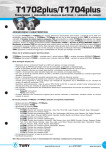
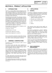
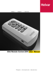
1
USER GUIDE
for the
HES92060
SINEWAVE DIMMER Module
HES92060
User Guide for the
Imagine HES92060 SINEWAVE DIMMER Module
Document 7860088 Issue 1 (27/02/03)
Copyright © 2002 Helvar Merca Ltd.
All rights reserved.
No part of this documentation may be reproduced or transmitted in any form or by any means, electronic or mechanical, including
photocopying and recording, without the prior written permission of Helvar Merca Ltd.
The information in this documentation is supplied without warranty of any kind, either directly or indirectly, and is subject to change without
prior written notice. Helvar Merca Ltd., its employees or appointed representatives will not be held responsible for any damages to software,
hardware, or data, howsoever arising as a direct or indirect result of the product(s) mentioned herein.
Issued by:
Helvar Merca Ltd.,
Hawley Mill,
Hawley Road,
Dartford,
Kent,
DA2 7SY,
United Kingdom.
www.helvar.co.uk
Printed in the United Kingdom.
PREFACE
PREFACE
Scope of this User Guide
The descriptions and instructions contained in this guide are based on the
assumption that the DIMMER module is being installed and used as part of a
Helvar Merca Ltd. Imagine Lighting System.
The installation instructions refer to the DIMMER module being installed in a
STACKER unit.
Technical Specifications
Any technical data required for the correct installation and use of the DIMMER
module is contained in this user guide.
Firmware Version
The operational instructions contained in this user guide assume that the DIMMER
module is using the following firmware version:
HES92060 version 1.0 firmware.
The dimmer module briefly reports the firmware version during power-up
test. Refer to section 2, page 10 for further details.
Trade Marks
IMAGINE™, SCENESET™, SCENEMAKER™, SCENETIMER™,
SCENE PLANNER™, SCENESOFT™, and SCENE COMMANDER™
are trade marks of Helvar.
7860088 issue 1
iii
HES92060 USER GUIDE
This page is intentionally left blank.
iv
7860088 issue 1
CONTENTS
CONTENTS
SECTION 1
INTRODUCTION
1
GENERAL DESCRIPTION . . . . . . . . . . . . . . . . . . . . . . . . . . . . . . . . . . . . . . . . . . . 2
EXTERNAL LAYOUT . . . . . . . . . . . . . . . . . . . . . . . . . . . . . . . . . . . . . . . . . . . . . . . 3
Front Panel . . . . . . . . . . . . . . . . . . . . . . . . . . . . . . . . . . . . . . . . . . . . . . . . 3
Rear Panel. . . . . . . . . . . . . . . . . . . . . . . . . . . . . . . . . . . . . . . . . . . . . . . . . . 3
Right Side Panel . . . . . . . . . . . . . . . . . . . . . . . . . . . . . . . . . . . . . . . . . . . . 3
Left Side Panel . . . . . . . . . . . . . . . . . . . . . . . . . . . . . . . . . . . . . . . . . . . . . . 3
SECTION 2
INSTALLING THE DIMMER
5
INPUT SUPPLY . . . . . . . . . . . . . . . . . . . . . . . . . . . . . . . . . . . . . . . . . . . . . . . . . . . . 6
Voltage Range . . . . . . . . . . . . . . . . . . . . . . . . . . . . . . . . . . . . . . . . . . . . . . 6
Frequency Range . . . . . . . . . . . . . . . . . . . . . . . . . . . . . . . . . . . . . . . . . . . . 6
Supply Protection . . . . . . . . . . . . . . . . . . . . . . . . . . . . . . . . . . . . . . . . . . . 6
INSTALLING INTO A STACKER UNIT . . . . . . . . . . . . . . . . . . . . . . . . . . . . . . . . . 7
REMOVAL PROCEDURE . . . . . . . . . . . . . . . . . . . . . . . . . . . . . . . . . . . . . . . . . . . . 9
SETTING-UP PROCEDURE . . . . . . . . . . . . . . . . . . . . . . . . . . . . . . . . . . . . . . . . 10
Stage 1 – Power-up Test . . . . . . . . . . . . . . . . . . . . . . . . . . . . . . . . . . . . . 10
Stage 2 – Output Test . . . . . . . . . . . . . . . . . . . . . . . . . . . . . . . . . . . . . . . 10
Stage 3 – Set the Output Channel Addresses . . . . . . . . . . . . . . . . . . . 11
SECTION 3
DIMMER OPERATING INSTRUCTIONS
13
CONTROLS AND DISPLAY FUNCTIONS . . . . . . . . . . . . . . . . . . . . . . . . . . . . . . 14
Display Modes. . . . . . . . . . . . . . . . . . . . . . . . . . . . . . . . . . . . . . . . . . . . . 14
Control Lock-out . . . . . . . . . . . . . . . . . . . . . . . . . . . . . . . . . . . . . . . . . . . 14
Default Mode . . . . . . . . . . . . . . . . . . . . . . . . . . . . . . . . . . . . . . . . . . . . . . 14
Changing the Display Mode . . . . . . . . . . . . . . . . . . . . . . . . . . . . . . . . . 15
OUTPUT LEVEL MODE . . . . . . . . . . . . . . . . . . . . . . . . . . . . . . . . . . . . . . . . . . . 16
Output Level . . . . . . . . . . . . . . . . . . . . . . . . . . . . . . . . . . . . . . . . . . . . . . 16
Operating Status . . . . . . . . . . . . . . . . . . . . . . . . . . . . . . . . . . . . . . . . . . . 16
S-DIM Data Line Status . . . . . . . . . . . . . . . . . . . . . . . . . . . . . . . . . . . . . 16
Changing the Output Level . . . . . . . . . . . . . . . . . . . . . . . . . . . . . . . . . . 17
SCENESET Control . . . . . . . . . . . . . . . . . . . . . . . . . . . . . . . . . . . . . . . . . . 17
Analogue Control . . . . . . . . . . . . . . . . . . . . . . . . . . . . . . . . . . . . . . . . . . 17
7860088 issue 1
v
HES92060 USER GUIDE
CHANNEL ADDRESS MODE . . . . . . . . . . . . . . . . . . . . . . . . . . . . . . . . . . . . . . 18
Control Lock-out . . . . . . . . . . . . . . . . . . . . . . . . . . . . . . . . . . . . . . . . . . . 18
Changing the Channel Address . . . . . . . . . . . . . . . . . . . . . . . . . . . . . . 19
HYSTERESIS MODE (Turn-on/ Turn-off Levels) . . . . . . . . . . . . . . . . . . . . 20
Changing the Turn-on and Turn-off Levels. . . . . . . . . . . . . . . . . . . . . 21
SCENESET NUMBER/INTERNAL TEMPERATURE DISPLAY MODE . . . . . . . . 22
Checking the SCENESET Number/Internal Temperature Display . . 22
OUTPUT LEVEL OVERRIDE . . . . . . . . . . . . . . . . . . . . . . . . . . . . . . . . . . . . . . . 23
Setting the Override Level . . . . . . . . . . . . . . . . . . . . . . . . . . . . . . . . . . . 23
SECTION 4
ANALOGUE CONTROL
25
ANALOGUE CONTROL . . . . . . . . . . . . . . . . . . . . . . . . . . . . . . . . . . . . . . . . . . . 26
Control Priority . . . . . . . . . . . . . . . . . . . . . . . . . . . . . . . . . . . . . . . . . . . . 26
Analogue Connector. . . . . . . . . . . . . . . . . . . . . . . . . . . . . . . . . . . . . . . . 26
Basic Analogue Control Circuit. . . . . . . . . . . . . . . . . . . . . . . . . . . . . . . 27
SECTION 5
DIMMER TROUBLESHOOTING
29
DIAGNOSTIC CODES . . . . . . . . . . . . . . . . . . . . . . . . . . . . . . . . . . . . . . . . . . . . . 30
‘Fatal’ Codes. . . . . . . . . . . . . . . . . . . . . . . . . . . . . . . . . . . . . . . . . . . . . . . 31
Self-recoverable Codes . . . . . . . . . . . . . . . . . . . . . . . . . . . . . . . . . . . . . . 32
Communication Codes. . . . . . . . . . . . . . . . . . . . . . . . . . . . . . . . . . . . . . 33
PROBLEM DIAGNOSIS . . . . . . . . . . . . . . . . . . . . . . . . . . . . . . . . . . . . . . . . 34
vi
7860088 issue 1
SECTION 1: INTRODUCTION
SECTION 1
INTRODUCTION
This section covers the following topics:
n
General Description.
n
External Layout.
7860088 issue 1
1
HES92060 USER GUIDE
GENERAL DESCRIPTION
The HES92060 DIMMER module provides a single channel of sinewave
dimming which can be controlled by the following methods:
·
·
·
Local Control (Integral Control Panel).
S-DIM (Serial DIMmer communications) Data Highway.
Analogue Control Input.
The HES92060 sinewave dimmer functions as an electronic variac by
smoothly scaling the natural input sine wave usually supplied to the
dimmer, giving out the same natural sine wave, but of a smaller amplitude.
The HES92060 is suitable for use with all mains dimmable lamp loads.
When used in an Imagine Lighting System, all of the DIMMER module’s
parameters are down-loaded from the SCENESET module via the S-DIM
data line.
IMPORTANT NOTE
The DIMMER module will not respond to S-DIM commands from an Imagine
System until the output channel address has been correctly set.
2
7860088 issue 1
SECTION 1: INTRODUCTION
EXTERNAL LAYOUT
Front Panel
Cover Plate for Power Connector
Function Label
Control Panel
Rear Panel
Digital Input/Output Connector
Right Side Panel
Analogue Input Connector
Left Side Panel
Power Connector
7860088 issue 1
3
HES92060 USER GUIDE
This page is intentionally left blank.
4
7860088 issue 1
SECTION 2: INSTALLING THE DIMMER
SECTION 2
INSTALLING THE DIMMER
This section covers the following topics:
n
Input supply requirements.
n
Installing into a STACKER unit.
n
Connections for supply and output.
n
Removal procedure.
n
Setting-up procedure.
7860088 issue 1
5
HES92060 USER GUIDE
INPUT SUPPLY
Voltage Range
The DIMMER module is supplied as a universal input for 115/230V a.c. operation.
·
HES92060 115V or 230V a.c. (nominal); 90V – 255V a.c. (absolute).
DC operation 90V – 250V d.c. contact Helvar for details.
Check that the module is set for the correct range for the intended power supply by
referring to the serial no./rating plate on the underside of the module.
CAUTION
Connecting a supply which exceeds the maximum limit may cause irreparable
damage to the DIMMER module.
Frequency Range
The input supply frequency should be within the the range 40 – 75Hz, or DC. A
supply frequency outside this range will cause the DIMMER module to shut-down.
Supply Protection
The rating of the fuse or MCB will depend on the method of DIMMER cooling
employed:
MCB/Fuse rating (per Channel)
6
Convection Cooled
Fan Cooled
4A
10A
7860088 issue 1
SECTION 2: INSTALLING THE DIMMER
INSTALLING INTO A STACKER UNIT
WARNING
For your own safety, before attempting to install the DIMMER module, ensure
that the input supply MCB is in the ‘off’ position and if possible, isolate the
MCB input terminal from the mains supply.
1. Carefully insert the DIMMER module into the appropriate slot of the
STACKER unit, ensuring that the rear connector locates firmly into the
motherboard at the back of the STACKER.
2. If required, secure the module to the STACKER by inserting a suitable retaining
screw on the left-hand side (see Fig.2-1).
3.
Fig.2-1: Location of retaining screw.
Insert the blade of a small flat-bladed screwdriver into the notch on
the terminal cover plate, and gently prise out the plate to gain access to the
terminal screws for the power connector (see Fig.2-2).
Fig.2-2: Removing the power terminal cover.
7860088 issue 1
7
HES92060 USER GUIDE
4. Using suitable cable, make the following connections between the DIMMER
module and the distribution panel:
DIMMER Module
Distribution Panel
Wire Colour
Terminal
Earth .
Green/Yellow.
Terminal N.
Neutral.
Blue.
Terminal LA.
Live feed from MCB.
Brown.
Terminal LB.
No Internal Connection
-
Terminal CHA.
Appropriate output terminal.
Red.
Terminal CHB.
No Internal Connection
-
Recommended cable type:
Cable size:
Stripping length:
Terminal screw torque:
TRI rated 105C (BS6231 approved).
2.5mm2.
12mm.
0.8Nm.
5. Clip the terminal cover back into position.
6. Write the function or circuit details of the channel on the label in the recessed
area of the front panel next to the terminal cover plate. If required, the label
may be removed as shown in Fig.2-3.
7. Make the connections, if required, to the analogue input, refer to page 26.
Fig.2-3: Removing the front panel label.
The physical installation of the DIMMER module is now complete. For the
testing and setting-up procedure, refer to page 10.
8
7860088 issue 1
SECTION 2: INSTALLING THE DIMMER
REMOVAL PROCEDURE
If a DIMMER module needs to be removed from the STACKER unit, ensure that
the channel address is known.
If not, check the address by following the instruction procedure in section
3, page 18. Then proceed as follows:
WARNING
For your own safety, before attempting to remove the DIMMER module,
ensure that the input supply MCB is in the ‘off’ position and if possible,
isolate the MCB input terminal from the mains supply.
1. Insert the blade of a small flat-bladed screwdriver into the notch on
the terminal cover plate, and gently prise out the plate to gain access to the
terminal screws for the power connector (see Fig.2-2).
2. Unscrew the terminals and withdraw each cable. It is suggested that the input
and output cables are identified with a label to assist reconnection.
3. If the DIMMER module (or a replacement) is not to be refitted immediately,
ensure that the ends of the connecting cables are made safe and secured away
from all other connections.
4. Unplug any leads to the analogue input connector on the right-hand side.
5. Remove the locking screw (if fitted) from the left-hand side of the
module (see Fig.2-1).
6. Grip the sides of the DIMMER firmly with both hands (through the slots
in either side of the STACKER) and carefully ease the module forward to
disengage the rear connector. Continue to ease the module out until the front is
clear of the other modules enabling it to be withdrawn.
7860088 issue 1
9
HES92060 USER GUIDE
SETTING-UP PROCEDURE
The setting-up procedure for the DIMMER module is divided into three stages,
which must be followed in the order listed below:
·
·
·
Stage 1 – Power-up Test.
Stage 2 – Output Test.
Stage 3 – Set the Output Channel Addresses.
If it is not required to test the output (i.e. to check for correct load operation and
wiring) then stage 2 may be omitted.
IMPORTANT NOTE
The DIMMER module will not respond to S-DIM commands from an Imagine
System until the output channel address has been correctly set (stage 3).
Stage 1 – Power-up Test
Turn on the supply to the DIMMER
module; the display will briefly
show ‘888 ’ then the firmware
versions, and then clear to show
the default display mode (Fig.2.4).
Fig.2-4: Default display.
If the display repeatedly flashes a 3 digit number , the module has
detected a problem. Refer to section 5, page 30 for further details.
Stage 2 – Output Test
CAUTION
Before attempting this test, ensure that any load connected to the DIMMER
module output is suited to Dimming . An incompatible load type may result in
damage to the module or the load.
Press and hold the top button on the DIMMER module’s control panel to turn-on
and raise the level of CHA (as indicated by the left-hand digit on the display).
Press and hold the lower button to return the output to zero level.
10
7860088 issue 1
SECTION 2: INSTALLING THE DIMMER
Stage 3 – Set the Output Channel Address
Before the DIMMER module can operate correctly as part of the Imagine System,
the Channel Address must be defined.
For details, refer to Section 3, page 18.
7860088 issue 1
11
HES92060 USER GUIDE
This page is intentionally left blank.
12
7860088 issue 1
SECTION 3: DIMMER OPERATING INSTRUCTIONS
SECTION 3
DIMMER OPERATING INSTRUCTIONS
This section covers the following topics:
n
Controls and Display Functions.
n
Output Level.
n
Channel Address.
n
Hysteresis (Turn-on and Turn-off Levels).
n
SCENESET Number.
n
Output Level Override.
7860088 issue 1
13
HES92060 USER GUIDE
CONTROLS AND DISPLAY FUNCTIONS
The DIMMER module has a control panel with two push-buttons and a three
character digital display (Fig.3-1).
Fig.3-1: DIMMER control panel.
Display Modes
The display can be used in six different modes.
·
·
·
·
·
·
Output Level.
Channel Address.
Dimming Law(Not used).
Hysteresis (turn-on & turn-off level).
SCENESET Number/internal dimmer temperature display.
Override Level.
Each mode allows a particular setting for the dimmer output to be viewed and if
required, a new value (except for the SCENESET number/temperature) can be
entered.
When controlled by a SCENESET module it is necessary to set the channel address
only. All other parameters will be set automatically.
Control Lock-out
The ability to change individual settings by using the integral control panel can be
disabled or ‘locked-out’ by the controlling SCENESET module.
When a setting is locked-out, it can only be modified by the controlling
SCENESET module.
Default Mode
The display defaults to Output Level Mode when the DIMMER module is
powered-up. The display will also return to this mode if no buttons are pressed for
ten seconds while another mode is selected.
14
7860088 issue 1
SECTION 3: DIMMER OPERATING INSTRUCTIONS
Changing the Display Mode
Procedure
Display & Buttons
1. With the display showing Output Level Mode, press
and hold the two buttons.
2. After one second approximately, the display will
change to the Channel Address Mode.
Maintaining pressure on both buttons will cause the
display to step through each mode.
Dimming Law Mode... (not used in HES92060)
Hysteresis Mode...
SCENESET Number/Internal Temperature Mode...
Override Mode...
Then back to Output Level Mode...
3. Releasing the buttons will select the mode currently
displayed.
4. If no further buttons are pressed within ten seconds,
the display will revert to Output Level Mode..
7860088 issue 1
15
HES92060 USER GUIDE
OUTPUT LEVEL MODE
In this mode, the display
shows the following
information:
·
Output Level.
·
Operating Status.
·
S-DIM Data Line Status.
Fig.3-2: Channel level mode display.
Output Level
The left-hand digit indicates the level of the output.
The level is expressed in terms of percentage control. Note that only the decade
(tens) component of the output level is displayed (see Fig.3-3):
Fig.3-3: Display conventions for output levels.
Operating Status
When this segment is illuminated in Channel Level Mode, it indicates that the
DIMMER module is operating normally.
S-DIM Data Line Status
When the S-DIM data highway is functioning correctly, this segment will blink
every time a valid S-DIM message has been received and decoded.
However, even if S-DIM messages are being received, this segment will not blink
until the channel address has been correctly set (see page 18).
16
7860088 issue 1
SECTION 3: DIMMER OPERATING INSTRUCTIONS
Changing the Output Level
The output level will normally be set by the controlling SCENESET module.
However, to change the level manually, proceed as follows:
Procedure
Display & Buttons
1. Check that the display is showing Output Level Mode.
2. To change the level of the output, press and hold
either the top button to increase the level or the
bottom button to decrease the level.
▲
▲
3. When the required level is shown, release the button.
SCENESET Control
When the DIMMER module is under SCENESET control, the output level is
checked periodically against the current scene. If the level is different (e.g. has
been changed manually), the SCENESET module will return the level to the
correct setting for that scene.
Analogue Control
The output level can also be set by using the analogue input. For further details,
refer to section 4, page 26.
7860088 issue 1
17
HES92060 USER GUIDE
CHANNEL ADDRESS MODE
This mode enables the address to be defined. The DIMMER module supports the
following addresses:
·
001 – 128
for use with the Imagine Lighting System.
·
001 – 252
for use with the Lighting Router System.
·
1 – 16
for use with 460 DALI-SDIM Converter System.
·
251 – 254
for use with the Ambience Lighting System.
When the DIMMER module is supplied, the address is factory set to 251.
IMPORTANT NOTE
The DIMMER module will not respond to S-DIM commands from an Imagine
System until the output channel address has been correctly set.
Control Lock-out
If an address is selected which has been ‘locked’ by the controlling SCENESET
module, that address cannot be changed again unless the SCENESET is
reprogrammed or the DIMMER module de-powered and the address reset before
an S-DIM message is received.
18
7860088 issue 1
SECTION 3: DIMMER OPERATING INSTRUCTIONS
Changing the Channel Address
Procedure
Display & Buttons
1. With the display showing Output Level Mode,
press and hold the two buttons.
2. Wait for the display to change to Channel Address
Mode (approximately one second) then release both
buttons.
To leave the address as it is, go to step 5.
▲
▲
3. To change the address, press and hold either the top
button to increase, or the bottom button to decrease
the number.
4. To store the new address shown, press and hold both
buttons until the display briefly shows ‘888 ’ to
confirm that the new value has been stored in the
DIMMER’s memory.
5. The display will revert to Output Level Mode
after storing the new address, or ten seconds
after releasing the buttons.
7860088 issue 1
19
HES92060 USER GUIDE
HYSTERESIS MODE (Turn-on/ Turn-off Levels)
This mode is used to set the percentage level at which the output turns on and off
(assuming maximum level is 100%). This is referred to as ‘hysteresis’ or as the
turn-on and turn-off levels.
The display will show a letter and a two-digit value. The letter indicates the
turn-off level and the digits show the turn-on level.
·
The turn-on level can be set between 2% and 64% in 2% increments.
·
The turn-off level can be set to be either 1% less than the turn-on level
(display shows the letter ‘r ’) or to 80% of the turn-on level (display shows
the letter ‘h ’).
When the DIMMER module is supplied, the output is set to a turn-on level of 2%
with a turn-off level of 1% (as example 1):
Example 1
Turn-on level = 2%.
Turn-off level ‘r ’
= (2 – 1)
= 1%.
Example 2
Turn-on level = 50%.
Turn-off level ‘h ’
Note:
20
= (50 x 0.8)
= 40%.
The turn-off level for the ‘h ’ setting is calculated to the nearest 0.5%.
7860088 issue 1
SECTION 3: DIMMER OPERATING INSTRUCTIONS
Changing the Turn-on and Turn-off Levels
Procedure
Display & Buttons
1. Press and hold the two buttons until the display shows
the Hysteresis Mode.
Note: The display will cycle through the turn-on levels
for ‘r ’ and ‘h ’ turn-off settings.
▲
▲
2. To change the setting, press and hold either the top
button to increase, or the bottom button to decrease
the setting.
To leave the setting as it is, go to step 4.
3. To store the new setting shown, press and hold both
buttons until the display briefly shows ‘888 ’ to
confirm that the new value has been stored in the
DIMMER’s memory.
4. The display will revert to Output Level Mode after
storing the levels, or ten seconds after releasing the
buttons.
7860088 issue 1
21
HES92060 USER GUIDE
SCENESET NUMBER/INTERNAL TEMPERATURE
DISPLAY MODE
In a large system, each DIMMER module can be connected to one of up to eight
SCENESET modules.
In this mode, the display will show the number of the controlling SCENESET
module. This is an advisory display only and cannot be changed.
The display will show the letters ‘ch ’ followed by a number from 1 to 8.
If the display shows ‘ch0 ’, then there is no SCENESET connected.
The display will then change to show the dimmer's internal temperature in Celcius
to aid diagnostics.
Checking the SCENESET Number/Internal Temperature
Procedure
Display & Buttons
1. Press and hold the two buttons until the display shows
the SCENESET Number Mode.
2. The display change to show the dimmer's internal
temperature in Celcius.
Ten seconds after the buttons are released.
2. The display will then revert to the level display mode,
after ten seconds, if no buttons are pressed.
22
7860088 issue 1
SECTION 3: DIMMER OPERATING INSTRUCTIONS
OUTPUT LEVEL OVERRIDE
The output can be pre-programmed with an override level. This is the level
that will be applied to the output if the DIMMER module’s Output Level
Override circuit is activated. The output is factory-set to full power (100%), but
this can be changed as required.
This function is normally used by the Watchdog facility on the controlling
SCENESET module.
Setting the Override Level
Procedure
Display & Buttons
1. Press and hold the two buttons until the display shows
the Override Mode.
2. To change the setting , press and hold either the top
button to increase or the bottom button to decrease the
setting.
▲
▲
3. To store the new setting, press and hold both buttons
until the display briefly shows '888'to confirm that
the new value has been stored in the DIMMER'S
memory.
4. The display will revert to Output Level Mode ten
seconds after releasing the buttons.
5. If the Level Override circuit is now activated, the
display will show the programmed level.
Also, vertical bars in the centre of the display will
move from side to side.
Note: Whilst Level Override is active, the output level
cannot be changed by the DIMMER module
controls.
7860088 issue 1
23
HES92060 USER GUIDE
This page is intentionally left blank.
24
7860088 issue 1
SECTION 4: ANALOGUE CONTROL
SECTION 4
ANALOGUE CONTROL
This section covers the following topics:
n
Control Priority
n
Analogue Connector.
n
Basic Control Circuit.
7860088 issue 1
25
HES92060 USER GUIDE
ANALOGUE CONTROL
As well as being controlled by the S-DIM data highway, the level of the
DIMMER output can also be set by a 0 – 10V analogue input.
The control level is directly proportional to the analogue input, e.g. 5V
input will give 50% control level, 10V will give 100%, etc.
Control Priority
If the output is controlled by both an S-DIM and analogue input, the input
which defines the highest output level will take priority.
Analogue Connector
This is located on the right-hand side of the DIMMER module (see Fig.4-1):
Pin
Function
1
1 0V ±0.5V supply (max. 10mA)
2
0 – 10V control input for CHA
3
12V high impedance supply
4
0V common
Fig.4-1: Analogue input connector.
Suitable mating connector:
Cable size:
Stripping length:
Recommended cable type:
Maximum cable length:
Helvar part no. T1704
(not supplied).
0.2 – 2.5mm2.
7mm.
Equipment wire.
100m.
To use 3-wire potentiometer style controls, pins 1, 2 and 4 are used.
To use current sink style or 2-wire controls, connect pins 2 and 3 together,
with pin 4 still used as the 0V common. Pin 1 is then unused .
26
7860088 issue 1
SECTION 4: ANALOGUE CONTROL
Basic Analogue Control Circuit
A typical 3-wire analogue control circuit is shown in Fig.4-2.
1
2
3
4
10k
Fig.4-2: Basic 3-wire analogue control circuit.
A typical 2-wire analogue control circuit is shown in Fig.4-3.
1
Current sink style
2-wire control
2
3
4
Fig.4-3: Basic 2-wire analogue control circuit.
7860088 issue 1
27
HES92060 USER GUIDE
This page is intentionally left blank.
28
7860088 issue 1
SECTION 5: DIMMER TROUBLESHOOTING
SECTION 5
DIMMER TROUBLESHOOTING
This section covers the following topics:
n
Diagnostic Codes.
n
Problem Diagnosis.
7860088 issue 1
29
HES92060 USER GUIDE
DIAGNOSTIC CODES
Whenever the DIMMER module detects an abnormal condition, a flashing
diagnostic code will be displayed on the front panel.
The codes fall into three categories:
·
·
·
‘Fatal’.
Self-recoverable.
Communication.
The tables on the following pages list the codes, their likely causes and what
action, if any, needs to be taken.
If a diagnostic code is displayed which is not listed, this may indicate an internal
fault condition. If this occurs, please call your service agent.
30
7860088 issue 1
SECTION 5: DIMMER TROUBLESHOOTING
‘Fatal’ Codes
In the event of a ‘Fatal’ Code , the output of the DIMMER module will be
automatically turned off (i.e. set to zero level). The output cannot be used until the
cause has been cleared.
Code
Likely Cause
Action
003
The mains frequency is not in the
range 40–75Hz.
Turn off the supply to the
DIMMER module for a few seconds,
then turn back on.
The mains supply is ‘noisy’.
Internal circuit fault.
If the code recurs, check the mains
frequency.
If the mains frequency is O.K. but the
code recurs, call for service.
004
Internal circuit fault.
Turn off the supply to the
DIMMER module for a few seconds,
then turn back on.
If the code recurs, call for service.
007
The internal circuit temperature
has exceeded 90C.
Internal circuit fault.
7860088 issue 1
Turn off the supply to the
DIMMER module immediately and
call for service.
Warning: Do not turn the supply back
on. Internal damage may have
resulted from the high temperature.
31
HES92060 USER GUIDE
Self-recoverable Codes
In the event of a Self-recoverable Code the DIMMER module will reduce the
current on the output. The output level cannot be increased until the cause has been
cleared.
Code
LikelyCause
Action
051
The internal circuit temperature
has exceeded 70C.
Check that all ventilation grilles
are free from obstructions.
Note: The output level will reduce.
If the module is not being
forced-air cooled, check that the
load for each output is not
exceeding 3A.
If the ventilation and loading are
O.K., call for service.
010
Output current has exceeded the
maximum of 10A.
Note: Output level will reduce.
009
Instantaneous peak current
(15.5A) has been exceeded. The
output will be turned off.
If the code does not clear, the
associated lighting circuit is
probably overloaded.
Hold the lower button in until the
level shows 'o_o '.This re-enables
the dimmer output.
If the error re-occurs, check the
load.
32
008
The hardware overcurrent
protection has been tripped.
Check the load for short circuits.
011
The supply voltage to the dimmer
has been exceeded. The output
level may be reduced.
Check the supply.
7860088 issue 1
SECTION 5: DIMMER TROUBLESHOOTING
Communication Codes
These are advisory codes and will not usually change the current status of the
DIMMER module. However, subsequent S-DIM or control panel commands may
be ignored until the code has been cleared.
Code
Likely Cause
Action
052
Error in S-DIM message.
The S-DIM message is ignored.
The condition should clear
automatically after ten seconds.
054
General error in S-DIM
communications link.
The S-DIM message is ignored.
The condition should clear
automatically after ten seconds.
056
Checksum error in S-DIM
message.
The S-DIM message is ignored.
The condition should clear
automatically after ten seconds.
156
230
231
Internal Communications error
between processors.
The condition should clear
automatically after ten seconds.
Repeated problems with the S-DIM data highway are most likely to be caused by
bad connections, data cables running through electrically ‘noisy’ environments or
incorrect configuration of other devices in the system.
If further advice is needed, contact the system installer or service agent.
7860088 issue 1
33
HES92060 USER GUIDE
PROBLEM DIAGNOSIS
If the DIMMER module fails to operate as expected, it is more likely to be the
result of incorrect setting-up and configuration than a fault with the module itself.
Alternatively, there may be a problem elsewhere in the system.
Before calling for service, check through the following list of problems and likely
causes:
Problem
Likely Cause & Remedy
Display is blank.
No power to power input LA.
Check appropriate MCB or fuse.
Output loads not dimming correctly.
Hysteresis set incorrectly
(see section 3, page 20).
Output not responding to S-DIM control.
Channel Addresses not correctly set
(see section 3, page 18).
Incorrect or faulty connections on the
S-DIM data line. Check that the rear
connector is fully seated on to the
STACKER motherboard.
DIMMER module is not connected to a
SCENESET (see section 3, page 22).
34
Channel Address cannot be changed by
the front panel controls.
The Channel Address is ‘locked-out’
by the SCENESET module.
A DIMMER parameter cannot be changed
by front panel controls.
The parameter is ‘locked-out’ by the
SCENESET module.
7860088 issue 1
HELVAR Merca Ltd.
Hawley Mill
Hawley Road
Dartford, Kent. DA2 7SY
United Kingdom.
Telephone:
Facsimile:
+44 (0)1322 222211.
+44 (0)1322 282216.
Part No. 7860088 issue 1