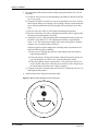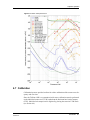
1
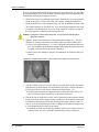
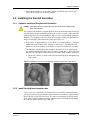
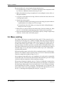
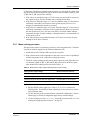
Trillium 120P Seismometer User Guide Nanometrics Inc. Kanata, Ontario Canada © 2005–2006 Nanometrics Inc. All Rights Reserved. Trillium 120P Seismometer User Guide The information in this document has been carefully reviewed and is believed to be reliable. Nanometrics, Inc. reserves the right to make changes at any time without notice to improve the reliability and function of the product. No part of this publication may be reproduced, stored in a retrieval system or transmitted, in any form or by any means, electronic, mechanical, photocopying, recording, or otherwise, without the prior written permission of Nanometrics Inc. Nanometrics, Inc. 250 Herzberg Road Kanata, Ontario, Canada K2K 2A1 Tel (613)592-6776 Fax (613)592-5929 Email [email protected] www.nanometrics.ca Part number 15149R3 Release date 2006-04-27 Contents Figures . . . . . . . . . . . . . . . . . . . . . . . . . . . . . . . . . . . . . . . . . . . . . . . . . . . . . . . . . . v Tables . . . . . . . . . . . . . . . . . . . . . . . . . . . . . . . . . . . . . . . . . . . . . . . . . . . . . . . . . vii Chapter 1 Introduction . . . . . . . . . . . . . . . . . . . . . . . . . . . . . . . . . . . . . . . . . . . . . . . . . . . . . . 1 Chapter 2 Preparation. . . . . . . . . . . . . . . . . . . . . . . . . . . . . . . . . . . . . . . . . . . . . . . . . . . . . . . 3 2.1 Site selection . . . . . . . . . . . . . . . . . . . . . . . . . . . . . . . . . . . . . . . . . . . . . . . . . . . . . . . . . . . 2.2 Pier construction . . . . . . . . . . . . . . . . . . . . . . . . . . . . . . . . . . . . . . . . . . . . . . . . . . . . . . . . . 2.2.1 Concrete selection . . . . . . . . . . . . . . . . . . . . . . . . . . . . . . . . . . . . . . . . . . . . . . . . . . . . . . 2.2.2 Vault wall decoupling . . . . . . . . . . . . . . . . . . . . . . . . . . . . . . . . . . . . . . . . . . . . . . . . . . . . 2.3 Thermal insulation . . . . . . . . . . . . . . . . . . . . . . . . . . . . . . . . . . . . . . . . . . . . . . . . . . . . . . . 2.4 Cable design. . . . . . . . . . . . . . . . . . . . . . . . . . . . . . . . . . . . . . . . . . . . . . . . . . . . . . . . . . . . 3 3 3 4 4 4 Chapter 3 Installation . . . . . . . . . . . . . . . . . . . . . . . . . . . . . . . . . . . . . . . . . . . . . . . . . . . . . . . 5 3.1 Unpacking the sensor . . . . . . . . . . . . . . . . . . . . . . . . . . . . . . . . . . . . . . . . . . . . . . . . . . . . . 5 3.2 Optional thermal insulation . . . . . . . . . . . . . . . . . . . . . . . . . . . . . . . . . . . . . . . . . . . . . . . . . 5 3.3 Orientation and levelling . . . . . . . . . . . . . . . . . . . . . . . . . . . . . . . . . . . . . . . . . . . . . . . . . . . 5 3.4 Installing the sensor cable . . . . . . . . . . . . . . . . . . . . . . . . . . . . . . . . . . . . . . . . . . . . . . . . . 8 3.5 Installing the thermal insulation . . . . . . . . . . . . . . . . . . . . . . . . . . . . . . . . . . . . . . . . . . . . . 9 3.5.1 Optional: Install the fibreglass batt insulation. . . . . . . . . . . . . . . . . . . . . . . . . . . . . . . . . . 9 3.5.2 Install the rigid foam insulation box . . . . . . . . . . . . . . . . . . . . . . . . . . . . . . . . . . . . . . . . . 9 3.6 Mass centring . . . . . . . . . . . . . . . . . . . . . . . . . . . . . . . . . . . . . . . . . . . . . . . . . . . . . . . . . . 10 3.6.1 Mass centring procedure . . . . . . . . . . . . . . . . . . . . . . . . . . . . . . . . . . . . . . . . . . . . . . . . 11 3.7 Installation checklist . . . . . . . . . . . . . . . . . . . . . . . . . . . . . . . . . . . . . . . . . . . . . . . . . . . . . 13 Chapter 4 Operation . . . . . . . . . . . . . . . . . . . . . . . . . . . . . . . . . . . . . . . . . . . . . . . . . . . . . . . 15 4.1 External connector . . . . . . . . . . . . . . . . . . . . . . . . . . . . . . . . . . . . . . . . . . . . . . . . . . . . . . 4.2 Sensor power . . . . . . . . . . . . . . . . . . . . . . . . . . . . . . . . . . . . . . . . . . . . . . . . . . . . . . . . . . 4.3 Control signals . . . . . . . . . . . . . . . . . . . . . . . . . . . . . . . . . . . . . . . . . . . . . . . . . . . . . . . . . 4.4 Output signals. . . . . . . . . . . . . . . . . . . . . . . . . . . . . . . . . . . . . . . . . . . . . . . . . . . . . . . . . . 4.5 Frequency response . . . . . . . . . . . . . . . . . . . . . . . . . . . . . . . . . . . . . . . . . . . . . . . . . . . . . 4.6 Self-noise . . . . . . . . . . . . . . . . . . . . . . . . . . . . . . . . . . . . . . . . . . . . . . . . . . . . . . . . . . . . . 4.7 Calibration. . . . . . . . . . . . . . . . . . . . . . . . . . . . . . . . . . . . . . . . . . . . . . . . . . . . . . . . . . . . . 4.8 State-of-Health . . . . . . . . . . . . . . . . . . . . . . . . . . . . . . . . . . . . . . . . . . . . . . . . . . . . . . . . . 4.9 Connecting and configuring the serial port . . . . . . . . . . . . . . . . . . . . . . . . . . . . . . . . . . . . 4.10 Troubleshooting and maintenance . . . . . . . . . . . . . . . . . . . . . . . . . . . . . . . . . . . . . . . . . . 15 15 16 16 18 19 21 22 22 26 Appendix A Specifications . . . . . . . . . . . . . . . . . . . . . . . . . . . . . . . . . . . . . . . . . . . . . . . . . . . . 27 A.1 A.2 A.3 A.4 A.5 Technology . . . . . . . . . . . . . . . . . . . . . . . . . . . . . . . . . . . . . . . . . . . . . . . . . . . . . . . . . . . . Performance . . . . . . . . . . . . . . . . . . . . . . . . . . . . . . . . . . . . . . . . . . . . . . . . . . . . . . . . . . . Interface . . . . . . . . . . . . . . . . . . . . . . . . . . . . . . . . . . . . . . . . . . . . . . . . . . . . . . . . . . . . . . Power . . . . . . . . . . . . . . . . . . . . . . . . . . . . . . . . . . . . . . . . . . . . . . . . . . . . . . . . . . . . . . . . Physical . . . . . . . . . . . . . . . . . . . . . . . . . . . . . . . . . . . . . . . . . . . . . . . . . . . . . . . . . . . . . . 27 27 28 28 28 iii Contents A.6 Environmental. . . . . . . . . . . . . . . . . . . . . . . . . . . . . . . . . . . . . . . . . . . . . . . . . . . . . . . . . . 28 Appendix B Connector Pinout . . . . . . . . . . . . . . . . . . . . . . . . . . . . . . . . . . . . . . . . . . . . . . . . . 29 Appendix C Generic Sensor Cable . . . . . . . . . . . . . . . . . . . . . . . . . . . . . . . . . . . . . . . . . . . . . 31 Appendix D Alignment Features . . . . . . . . . . . . . . . . . . . . . . . . . . . . . . . . . . . . . . . . . . . . . . . 33 iv Figures 1-1 Trillium 120P seismometer. . . . . . . . . . . . . . . . . . . . . . . . . . . . . . . . . . . . . . . . . . . . . . . . . 1 3-1 Fibreglass batt insulation under a seismometer (Trillium 240 model shown) . . . . . . . . . . 6 3-2 Sensor alignment using the North-South lines on the base . . . . . . . . . . . . . . . . . . . . . . . . 7 3-3 Sensor alignment using a staked line and the North-South guide . . . . . . . . . . . . . . . . . . . 8 3-4 Wrapping a sensor with fibreglass batt insulation (Trillium 240 model shown) . . . . . . . . . 9 3-5 Mass position adjustment access seal screws. . . . . . . . . . . . . . . . . . . . . . . . . . . . . . . . . 12 4-1 Sensor axis orientations. . . . . . . . . . . . . . . . . . . . . . . . . . . . . . . . . . . . . . . . . . . . . . . . . . 17 4-2 Nominal frequency response . . . . . . . . . . . . . . . . . . . . . . . . . . . . . . . . . . . . . . . . . . . . . . 19 4-3 Trillium 120P self-noise . . . . . . . . . . . . . . . . . . . . . . . . . . . . . . . . . . . . . . . . . . . . . . . . . . 20 4-4 Trillium 120P performance . . . . . . . . . . . . . . . . . . . . . . . . . . . . . . . . . . . . . . . . . . . . . . . . 21 D-1 Alignment features top view . . . . . . . . . . . . . . . . . . . . . . . . . . . . . . . . . . . . . . . . . . . . . . . 34 D-2 Alignment features bottom view . . . . . . . . . . . . . . . . . . . . . . . . . . . . . . . . . . . . . . . . . . . . 35 v Figures vi Tables 3-1 Mass position output voltage indicating need for mass centring . . . . . . . . . . . . . . . . . . . 11 4-1 Axis orientation and polarity of XYZ outputs . . . . . . . . . . . . . . . . . . . . . . . . . . . . . . . . . . 16 4-2 Poles and zeroes . . . . . . . . . . . . . . . . . . . . . . . . . . . . . . . . . . . . . . . . . . . . . . . . . . . . . . . 18 4-3 Serial port commands . . . . . . . . . . . . . . . . . . . . . . . . . . . . . . . . . . . . . . . . . . . . . . . . . . . 23 B-1 Connector pinout . . . . . . . . . . . . . . . . . . . . . . . . . . . . . . . . . . . . . . . . . . . . . . . . . . . . . . . 29 C-1 Generic sensor cable wiring for CBL13942R2 . . . . . . . . . . . . . . . . . . . . . . . . . . . . . . . . . 32 vii Tables viii Chapter 1 Introduction Trillium Model 120P is a three-component, broadband low-noise seismometer suitable for portable and fixed applications. It operates over a wide temperature range without manual recentring and has low power consumption. Its extended low frequency range, low noise, and wide dynamic range make it ideal for teleseismic studies as well as for regional and local events. At only 7.2kg and 21cm in diameter, the Trillium 120P is compact and portable. Figure 1-1 Trillium 120P seismometer Trillium seismometers have a symmetric triaxial arrangement of the sensing elements. The use of three identical axis elements ensures the same frequency response for vertical and horizontal outputs, is less susceptible to rapid changes in temperature, and guarantees true orthogonality of the three outputs. Data output of XYZ or UVW can be selected remotely, allowing calibration of the elements independently of the electronics. UVW data may also be used instead of XYZ for seismic signal recording, if desired. Please read the appropriate sections of this manual before transporting, storing, installing, or operating the Trillium 120P. If you need technical support, please submit your 15149R3 2006-04-27 Trillium 120P Seismometer User Guide 1 Chapter 1: Introduction request by email or fax. Include a full explanation of the problem and supporting data, to help us direct your request to the most knowledgeable person for reply. Before returning a unit for repair, contact Nanometrics Support to obtain an RMA number. Email: [email protected] FAX: To: Support +1 (613) 592-5929 2 Trillium 120P Seismometer User Guide 15149R3 2006-04-27 Chapter 2 Preparation This chapter provides general preinstallation guidelines for the Trillium 120P. These are intended to help achieve the best possible performance, but some guidelines may not be applicable for all types of site or study. 2.1 Site selection There is no substitute for a geological survey when it comes to site selection, so that the structures over which the sensor is to be installed are known. Low porosity is important as water seepage through the rock can cause tilts which overwhelm the seismic signal at long periods. Clay soils and to a lesser extent sand are especially bad in this sense. A seismic sensor should be installed on bedrock whenever possible, and as far away as possible from sources of cultural noise such as roads, dwellings, and tall structures. 2.2 Pier construction It is recommended that piers be rectangular (rather than round) whenever possible. Rigid foam thermal insulation boxes can be made to fit a rectangular pier more easily. The pier should be 2" to 4" thick. The surface area should be sized to accommodate the sensors and associated cabling as well as any foam insulation boxes which are to be used. The surface of the pier should be as smooth and level as possible and clear of debris. 2.2.1 Concrete selection The concrete used in a seismic pier should be as homogeneous as possible to avoid inducing tilts due to differing thermal coefficients of expansion. Therefore, no aggregate should be used and the concrete should be free of air bubbles. Since strength is not a concern in a seismic pier no steel reinforcing is needed. The recommended mixture is 50% Portland cement and 50% sieved sand (see Uhrhammer et. al., 1997; http://www.orfeus-eu.org/wg/wg2/guidelines/guidelines.htm). After the concrete is poured it should be shaken to allow trapped bubbles to escape. The concrete will have sufficiently hardened to set up the sensor after 24 hours. However the 15149R3 2006-04-27 Trillium 120P Seismometer User Guide 3 Chapter 2: Preparation pier may still generate spurious signals as the concrete cures, which can take two to four weeks. 2.2.2 Vault wall decoupling When setting up the forms for the concrete be sure to include a gap between the edge of the concrete and the walls of the vault. This decoupling of the pier from the vault wall is important because otherwise wind or other non-seismic forces acting on the walls can be transferred to the pier. These forces may cause the pier to tilt or twist and obscure the desired seismic signal. These signals are mostly long period, so vault wall decoupling is critical for quiet site long period studies. 2.3 Thermal insulation All broadband sensors are sensitive to temperature variations. Even at a very temperature-stable site, they must have some form of thermal insulation. Insulation serves to attenuate the ambient temperature variations, to isolate the sensor from drafts, and to localize and minimize air convection currents. We have repeatedly seen in our testing the critical importance of thermal insulation to long period noise performance with a variety of sensors and sites. We recommend wrapping a layer of fibreglass batt insulation around the Trillium 120P, and then installing a rigid foam insulation box. See also Section 3.5, “Installing the thermal insulation,” on page 9. 2.4 Cable design Cable design guidelines: Sensor cables should be designed for good EMI shielding. This is most easily accomplished using double-shielded twisted-pair cable. The twisted pairs provide magnetic shielding, an inner shield grounded at the digitizer provides good electric field shielding, and a continuous outer shield provides good high-frequency RF shielding. The outer shield should be earthed at the digitizer for safety. The digital ground (DGND) must be used for the return currents of the control signals (U_CALEN, V_CALEN, W_CALEN, UVW/TX, and SP/RX). The analog ground (AGND) must be used for the return currents of the analog signals (CAL_SIG, U_MP, V_MP, and W_MP). Note that AGND is connected to chassis ground (CHGND) inside the Trillium 120P, so if these signals are already connected at the digitizer, AGND should not be connected through the cable or else a ground loop will be created. See Appendix B for the connector pinout. 4 Trillium 120P Seismometer User Guide 15149R3 2006-04-27 Chapter 3 Installation Once the vault has been prepared, use the procedures described in this chapter to install the Trillium 120P. Section 3.7 on page 13 provides a generic installation checklist. 3.1 Unpacking the sensor The Trillium 120P is shipped in a very sturdy triple-wall coated cardboard box with custom-cut cushioning foam. To minimize the possibility of damaging the sensor, do not remove it from the box until it is ready to be placed directly on the pier. Save the box and foam in case the sensor needs to be shipped again. A removable lifting handle has been provided with your seismometer. You can use the lifting handle to facilitate installation of the sensor in vaults which are accessible only from the top. Do not use the lifting handle to carry the Trillium 120P. To use the lifting handle, screw it securely into the threaded hole at the center of the sensor cover. Remove the lifting handle once the sensor is installed. 3.2 Optional thermal insulation To maximize long period performance, we recommend wrapping fibreglass batt insulation around and under the Trillium 120P, and then installing a rigid foam insulation box. For some installations, one or the other will be sufficient, or may not be required. 3.3 Orientation and levelling Three alignment features are integral to the Trillium 120P: vertically scribed marks on the North-South axis, a North-South guide on the top of the case, and 5/16" diameter holes for alignment rods oriented to East-West. To level the Trillium 120P, use the three adjustable-height feet with lock nuts and the levelling bubble on the cover. For the most precise alignment possible two 5/16" diameter holes aligned to East-West are provided in the sensor base, into which 5/16" alignment rods (not supplied) can be fitted. Using the North-South alignment marks to align visually with an accurately scribed North-South mark on the pier will be precise enough for most installations. The sensor can also be precisely oriented to a stretched line (such as a length of fishing line) 15149R3 2006-04-27 Trillium 120P Seismometer User Guide 5 Chapter 3: Installation by using a straight-edge held against the guide on the top of the sensor. See Appendix D for top and bottom views of the Trillium 120P showing the relative orientation of the North-South and East-West alignment features. 1. Draw a line on the pier parallel to North-South. Alternatively, if you are using the North-South guide, you may stake a line (for example, fishing line) parallel to North-South directly over the location where you want to install the Trillium 120P. The North-South line (or East-West line, if you are using the alignment rods) must be aligned to true North (East). If you are using a magnetic compass, account for the local magnetic declination when drawing the line. Caution Fibreglass insulation may irritate skin. Use gloves when handling fibreglass batt insulation. 2. Optional: Prepare the bottom layer of thermal insulation (Figure 3-1). This is to eliminate air currents between the pier and the underside of the Trillium 120P. a) Place a layer (approximately 1" or 3cm) of fibreglass batt insulation flat on the pier. The insulation should be thick enough to take up the air gap but should not be tightly compressed once the sensor is installed. b) Make holes in the insulation, spaced to accommodate the Trillium 120P levelling feet. Figure 3-1 Fibreglass batt insulation under a seismometer (Trillium 240 model shown) 3. Take the Trillium 120P out of its box and place it gently down on the pier aligned approximately to North-South. The North marker line on the Trillium 120P base is the one just to the left of the sensor connector and label (Figure 3-2). Ensure that no insulation is caught under the levelling feet of the sensor. All three levelling feet must rest directly on the surface of the pier. 4. Unlock the feet as required to level the sensor, and then lock them again by threading the lock nut up until it engages firmly with the base. Note that the locknut has a mechanical stop that prevents it from loosening more than a third of a turn. It may be necessary to hold the body of the levelling foot still while locking the nut to avoid disturbing the levelness of the sensor. Extend the levelling feet as little as possible to achieve a level sensor. Keep at least one of the feet (two, if possible) retracted fully into the sensor base. 6 Trillium 120P Seismometer User Guide 15149R3 2006-04-27 Chapter 3: Installation 5. Align the sensor precisely to North-South: If you are using a scribed line on the pier, align the line drawn on the pier with the vertical North-South lines on the base (Figure 3-2). Some care is required to avoid sighting at an angle and introducing a parallax error. (Pull the insulation back as required to see the alignment line on the pier.) If you are aligning to a North-South staked line, hold a straight-edge in the North-South guide on top of the sensor case (Figure 3-3 on page 8) and align the straight-edge to the staked line. 6. After you have aligned the sensor to North-South, the sensor may need to be relevelled due to unevenness in the pier. While the sensor will operate properly with the bubble anywhere inside the black ring on the level, the bubble should be centred as precisely as possible to ensure the Z output is measuring true vertical motion. 7. Check the alignment again after levelling. Figure 3-2 Sensor alignment using the North-South lines on the base 15149R3 2006-04-27 Trillium 120P Seismometer User Guide 7 Chapter 3: Installation Figure 3-3 Sensor alignment using a staked line and the North-South guide Place the sensor under a line staked to North-South: Hold a straight-edge in the North-South guide flush to the inside edge, and align to the staked line: 3.4 Installing the sensor cable 1. Connect the sensor cable. The cable should be strain-relieved to the pier at some point close to the sensor. Strain relief can be accomplished with tie-wraps and tiewrap anchors, or with a heavy object. 8 Trillium 120P Seismometer User Guide 15149R3 2006-04-27 Chapter 3: Installation 2. Ensure that the digitizer case is solidly earthed, and that the outer shield of the cable and the sensor case are thereby earthed. 3.5 Installing the thermal insulation 3.5.1 Optional: Install the fibreglass batt insulation Caution Fibreglass insulation may irritate skin. Use gloves when handling fibreglass batt insulation. The Trillium 120P should be wrapped lightly on the sides and bottom (but not the top) with fibreglass batt style insulation (usually pink or yellow in colour). This eliminates residual convection air currents around the sensor which can disturb long period performance. The insulation works best when it is not tightly compressed, and when it is snugly but not tightly fitted around the sensor (see Figure 3-4). Wrap a layer of approximately 2" (5cm), about 12" (30cm) wide by 3' (1m) long snugly around the Trillium 120P, forming a vertical “pipe”. The fibreglass will adhere to itself at the overlap, so no adhesive or tape is needed to keep it in place. The fibreglass pipe should be snug enough so that there are no air gaps between the insulation and the sides of the sensor, but loose enough that it can be slid up off the sensor or replaced by sliding down over the sensor easily, without using force. Do not cover the top, to ensure heat can be dissipated properly through the top of the sensor. Figure 3-4 Wrapping a sensor with fibreglass batt insulation (Trillium 240 model shown) 3.5.2 Install the rigid foam insulation box For the outer layer of insulation, we recommend a five-sided box constructed using rigid polystyrene or polyisocyanuratic foam insulation. Alternatively, rigid foam insulation with foil on one side can be used. There are two advantages to the foil-coated foam: it has a higher insulation resistance, and the joints can be made using packing tape which is quicker and less messy than glue. 15149R3 2006-04-27 Trillium 120P Seismometer User Guide 9 Chapter 3: Installation Recommendations for constructing the thermal insulation box: Use insulation that is at least 2" (5cm) thick. Depending on the temperature stability of the site, additional or thicker boxes may be used. Make the insulation box large enough that it is not touching the sensor, cables, or fibreglass insulation. Cut a groove in the bottom of one edge of the box to allow the sensor cable to exit at the appropriate point. Seal the box joints properly: For rigid foam without a foil coating, glue the joints using polystyrene adhesive or polyurethane resin, taking care to leave no gaps. For rigid foam with a foil coating, you can tape the joints with packing tape, taking care to leave no gaps. Ensure there is a good seal between the bottom edge of the box and the pier. Adhesive 0.5" (1.25cm) thick weatherstripping can be used to ensure a good seal. Ensure the thermal insulation box is held firmly in place by setting a weight on top of the box. A brick works well for this purpose. 3.6 Mass centring The Trillium 120P masses are centred at the factory at 20°C. If the sensor is level, it will operate over the range ±45°C without recentring. If the sensor is not levelled accurately then the operational temperature range will be reduced. The Trillium 120P can be mass centred if the sensor is within ±1.5° of level, although it is good practice to ensure the sensor is levelled as precisely as possible before centring the masses. Once the Trillium 120P has been precisely mass centred (that is, the mass position voltage is within the range ±0.3V), the sensor can tolerate a shift of up to ±0.2° without mass recentring being required. Different operating ranges can be achieved by recentring the masses at different temperatures. For example, to achieve operation from –20°C to 50°C the masses should be centred at a temperature within the range 5 to 25°C. After temperature has stabilized in a new installation, it is good practice to physically recentre the booms. This ensures the unit will then be able to tolerate up to ±45°C range variation in ambient temperature without requiring recentring. When using a Nanometrics digitizer such as a Taurus or Trident that is connected to a network, you can read the mass position status remotely. For the Taurus, use options in the Sensor page either locally or on an external browser. For the Trident, use options on the Nanometrics UI Trident > Operation > Instrument page, or use NaqsView. The mass position status is also reported digitally via the RS-232 serial interface (see Section 4.9, “Connecting and configuring the serial port,” on page 22). 10 Trillium 120P Seismometer User Guide 15149R3 2006-04-27 Chapter 3: Installation To determine whether mass centring needs to be done you can check the voltage readings on the mass position outputs for each of the three sensor channels (signals U_MP, V_MP, and W_MP, referenced to AGND): If the values are outside the range ±3.5V the sensor may not be able to report seismic signals properly. For this condition, mass centring must be done. If the values are within the range ±3.5V but not within the range ±2V the sensor is sufficiently centred that it will report seismic signals properly. However, it is strongly recommended the masses be recentred. If the values are within the range ±2V but not within the range ±0.3V the sensor is sufficiently centred that it will report seismic signals properly. However, the closer the mass positions are to 0V, the more room there is to tolerate further ambient temperature changes. For this condition, centring the masses is recommended if it is convenient to do so. If the mass positions are all within the range ±0.3V there is no need to recentre, although it can be done if desired. 3.6.1 Mass centring procedure This procedure requires a 2.0mm hex screwdriver with a long shaft and a 2.5mm hex screwdriver (both are supplied in the Trillium maintenance kit). 1. Install and level the Trillium 120P as precisely as possible. 2. Wait at least 4 hours for the temperature of the sensor case to come to equilibrium with the temperature of the vault before centring the masses. 3. Check the voltage readings on the mass position outputs for each of the three sensor channels (signals U_MP, V_MP, and W_MP, referenced to AGND) to determine whether mass centring needs to be done (Table 3-1). Table 3-1 Mass position output voltage indicating need for mass centring Mass position output voltage Need to centre the masses? outside the range ±3.5V yes within the range ±3.5V but not within the range ±2V strongly recommended within the range ±2V but not within the range ±0.3V recommended, if it is convenient mass positions are all within the range ±0.3V no, although it can be done if desired 4. Set the sensor in short period response mode using any of these methods: Pull the SP/RX control signal (pin C) high (+5V to +15V) referenced to DGND (pin R). The SP/RX pin must remain high for the sensor to be in short period response mode. Use the interface for the connected Taurus (Advanced Configuration > Sensor Details page) or Trident (Configuration page Sensor Control settings). Use the serial port to issue a ShortPer command (see also Section 4.9, “Connecting and configuring the serial port,” on page 22). 15149R3 2006-04-27 Trillium 120P Seismometer User Guide 11 Chapter 3: Installation 5. For each channel with a mass position voltage output greater than ±0.3V, do the following: a) Locate the access seal screw corresponding to the channel of interest using Figure 3-5 as a guide. b) Using the 2.5 mm hex screwdriver, remove the appropriate seal screw. Inspect the O-ring for damage (for example, cuts or pitting), and get a replacement seal screw from the maintenance kit if the original seal screw appears to be damaged. c) Place the seal screw where it will remain clean during the procedure. d) Insert the 2.0 mm hex screwdriver straight down the hole until it engages with the mass position adjustment screw head. e) Adjust the screw by small increments while monitoring the mass position output until it is less than ±0.3 V. The adjustment sensitivity is approximately 1turn = 1volt. The mass position output will increase in the positive direction when the screw is turned counter-clockwise. If the mass position output voltage does not change when you turn the screw, check the following three conditions: Ensure you are adjusting the channel corresponding to the mass position output being monitored. Ensure the sensor is in short period mode, otherwise the mass position outputs will change far too slowly to be useful in centring the masses. If the mass position output is greater than ±3.5V, ensure the sensor is precisely levelled, and be sure to turn the screw clockwise if the voltage is positive and counter-clockwise if the voltage is negative. f) Using the 2.5 mm hex wrench, replace the seal screw. Tighten the seal screw to hand-tight (9 inch-pounds). 6. Set the sensor back to long period response mode. Figure 3-5 Mass position adjustment access seal screws 12 Trillium 120P Seismometer User Guide 15149R3 2006-04-27 Chapter 3: Installation 3.7 Installation checklist This checklist can be used as an aid when installing the Trillium 120P: Pier is clear of debris Sensor is level Sensor is aligned to North-South or East-West Sensor feet are locked Sensor serial number is noted Cable is connected to the sensor and the digitizer Cable is strain-relieved to the pier Cable is not touching the sensor case Masses are centred after temperature equalization (at least 4 hours post-installation) Thermal insulating box and fibreglass insulation are in place Thermal insulating box is not touching the sensor, cables, or fibreglass insulation Thermal insulating box is weighted down 15149R3 2006-04-27 Trillium 120P Seismometer User Guide 13 Chapter 3: Installation 14 Trillium 120P Seismometer User Guide 15149R3 2006-04-27 Chapter 4 Operation This chapter provides operating parameters and instructions for the Trillium 120P. 4.1 External connector The Trillium 120P connector is a 19-pin male military circular type hermetic connector. The pinout is given in Appendix B. 4.2 Sensor power The Trillium 120P can be powered using a DC source that can sustain 9V to 36V at the sensor connector. Voltage drops over the cable must be accounted for, and so the supply voltage at the source may need to be higher. In normal operation (the sensor is level and well centred, there is a low seismic signal, the sensor has settled for at least 30 minutes, and serial transmit is disabled) the power consumption is typically 650mW. On startup, the peak power surge may be up to 4.5W briefly. Power consumption above normal quiescent after the initial power on in-rush is roughly proportional to the output signal. If the sensor is not centred or has not yet settled, the output signals will be at the maximum, and power consumption may be as high as 3W. For a settled, centred, and level sensor, a seismic signal that approaches the sensor’s maximum clip level may draw as much as 2W peak (the average power consumption would be much lower). For long cables, be sure to account for the resistive voltage drop due to the cable itself. For example, 50m of 24AWG wire has a resistance of 4.2Ω in each direction. Therefore the voltage drop due to the possible 500mA startup in-rush at 9V would be 4.2V, and the power supply must be able to briefly supply 13.2V for this length of cable. The supply should also be able to sustain a 2W peak output at a voltage that guarantees the sensor receives 9V. For the 50m cable example, the peak current would be 220mA at 9V, and the voltage drop would be 1.9V, so the supply must be able to provide 220mA at 10.9V to reliably power the sensor for maximum seismic signals when using a 50m cable. 15149R3 2006-04-27 Trillium 120P Seismometer User Guide 15 Chapter 4: Operation 4.3 Control signals Trillium 120P has 5 digital control inputs: SP/RX, UVW/TX, U_CALEN, V_CALEN, and W_CALEN. All of these inputs are optically isolated from both the input voltage and the output and calibration input signals. Therefore, signals applied to these pins must be referenced to DGND rather than ±PWR or AGND. All of these inputs are active-high. Specifically, any voltage greater than 3.5V at a current greater than 0.1mA enables the relevant functionality while any voltage less than 1V or a high impedance disables it. All inputs can tolerate at least ±15V except for UVW/TX which can tolerate voltages from –7V to +15V. 4.4 Output signals The sensitivity specified in Table 4-2 on page 18 assumes an infinite input impedance at the digitizer. For digitizers with low input impedance it will become necessary to account for the fact that source impedance of the differential outputs is 300Ω ±1% (150Ω each output). A control signal switches the Trillium 120P output signal to either UVW output or XYZ output. The “natural” sensor output is UVW; in this mode the outputs represent the actual motion of the masses of the three sensor components. The “conventional” sensor output is XYZ; in this mode the outputs represent horizontal and vertical motion. See Table 4-1 for the polarities of the XYZ outputs and their correspondence to the directions of the compass. Table 4-1 Axis orientation and polarity of XYZ outputs Axis Orientation Positive voltage represents ... X east-west ... case motion to east Y north-south ... case motion to north Z vertical ... case motion upwards To select the sensor outputs: To select the UVW outputs, pull the UVW/TX pin high. To select the XYZ outputs, either leave the UVW/TX pin floating or set it to 0V. The sensor responds to changes on this control line within 4 seconds. Note that this input control signal is disabled when the sensor is transmitting on the serial port, since this pin is then used as the RS-232 serial TX output signal. (See Section 4.9, “Connecting and configuring the serial port,” on page 22.) To understand the difference between the UVW and XYZ outputs, refer to Figure 4-1. The sensor axes have been designed so that they are identical and so that the directions in which they sense motion are orthogonal. The U axis was chosen to be aligned with the East-West axis when projected into the horizontal plane. 16 Trillium 120P Seismometer User Guide 15149R3 2006-04-27 Chapter 4: Operation Figure 4-1 Sensor axis orientations Z V Y U W X This arrangement results in the following transformation equations: 2 0 u 1-----⋅ –1 3 v = 6 w –1 – 3 x 1 y = ------- ⋅ 6 z 2 x 2 ⋅ y z 2 (EQ 1) 2 –1 –1 0 2 u 3 – 3 ⋅ v w 2 2 (EQ 2) The first equation is implemented mechanically in the orientation of the Trillium 120P individual sensor axes. The second equation is implemented electronically when the Trillium 120P is in XYZ mode. Alternatively, seismic data may be digitized with the Trillium 120P in UVW mode and the transformation to horizontal and vertical signals implemented optionally when the data are processed. This allows for studies and calibrations where both UVW and XYZ data are required. 15149R3 2006-04-27 Trillium 120P Seismometer User Guide 17 Chapter 4: Operation 4.5 Frequency response The frequency response of the Trillium 120P can be measured using the calibration coil. During calibration, the measured response is the product of the calibration system’s lowpass response (a single pole at –158rad/s) and the sensor’s own response. Therefore, the seismometer response to ground motion is obtained by dividing the “combined response” obtained during calibration by the calibration input nominal transfer function. These three transfer functions are shown in Figure 4-2. The nominal poles ( p n ), zeroes ( z n ), normalization factor ( k ), and normalization frequency ( f 0 ), and passband sensitivity ( S sensor ) of the Trillium 120P are listed in Table 4-2. These parameters define the transfer function according to this equation: ∏ ( s + zn ) V ⋅ sn --------F(s) = S sensor ⋅ k ⋅ --------------------------m ∏ ( s + pn ) (EQ 3) n Where the normalization factor is defined as follows: 1 k = ---------------------------------------------------∏ ( i ⋅ 2 ⋅ π ⋅ f0 + zn ) (EQ 4) n ------------------------------------------------∏ ( i ⋅ 2 ⋅ π ⋅ f0 + pn ) n Table 4-2 Poles and zeroes Parameter zn Zeroes Nominal values Units 0 0 –106 –158 rad/s –0.03859 ±0.03649i –190 –158 ±193i –639 ±1418i pn Poles k Normalization factor 1.695 x 10⁹ S sensor Passband sensitivity at 1Hz 1201.0 V·s/m f0 Normalization frequency 1 Hz rad/s The transfer function is approximately flat from 120s to 50Hz and rolls off at 40dB/decade below the lower corner frequency, as shown in Figure 4-2. 18 Trillium 120P Seismometer User Guide 15149R3 2006-04-27 Chapter 4: Operation Figure 4-2 Nominal frequency response 4.6 Self-noise Typical Trillium 120P self-noise is plotted in Figure 4-3. Three curves are included for reference: Peterson’s new low-noise model (NLNM) and new high-noise model (NHNM), and McNamara and Buland’s PDF Mode Low Noise Model (MLNM).1 The noise floor specification is valid when the masses are centred within ±0.4V. The noise floor in the low frequency area will increase if the masses are further decentred. The self-noise at 100 seconds could rise to as high as –168dB if the masses are off centre by the maximum ±4.5V. Therefore to obtain the best low noise performance, it is best to ensure the masses are well centred. 1. See also: Peterson, J. (1993). Observations and Modeling of Seismic Background Noise. Open-file report 93-922, U. S. Geological Survey. McNamara, D.E., and R. P. Buland (1994). Ambient Noise Levels in the Continental United States. Bull. Seism. Soc. Am., 94, 1517–1527. Clinton, J. F., and T. H. Heaton (2002). Potential Advantages of a Strong-motion Velocity Meter over a Strong-motion Accelerometer. Seism. Res. Lett., 73, 332–342. 15149R3 2006-04-27 Trillium 120P Seismometer User Guide 19 Chapter 4: Operation The noise floor shown is the typical level of instrument self-noise assuming proper installation. To achieve best performance for any sensor, meticulous attention to detail must be paid to choice of site, vault design, and sensor installation. The New Manual of Seismological Observatory Practice (IASPEI 2002) has a good discussion of the relevant best practices (see the publisher’s site http://www.gfz-potsdam.de/pb2/pb21/ for information on the NMSOP). Figure 4-3 Trillium 120P self-noise To determine the dynamic range at frequencies of interest for your application, compare the noise floor to the sensor clip level using Figure 4-4. In this figure, for comparison of noise floors to clip levels, we convert power spectral densities using octave bandwidths and an RMS-to-peak conversion factor of 1.253. 20 Trillium 120P Seismometer User Guide 15149R3 2006-04-27 Chapter 4: Operation Figure 4-4 Trillium 120P performance 4.7 Calibration Calibration inputs are provided to allow for relative calibration of the sensor across frequency and over time. Since the Trillium 120P is a symmetric triaxial sensor, calibration must be performed on the individual sensor axes (UVW) rather than the horizontal and vertical outputs (XYZ). Individual axis outputs can be digitized by placing the sensor in UVW mode (see Section 4.4). 15149R3 2006-04-27 Trillium 120P Seismometer User Guide 21 Chapter 4: Operation Each axis has a separate calibration enable signal: U_CALEN, V_CALEN, W_CALEN. All axes use a common calibration input signal (CAL_SIG) which has a nominal sensitivity of 0.010m/s2·V. 4.8 State-of-Health Mass position output signals U_MP, V_MP, and W_MP are provided to monitor the effect of tilt and temperature on the spring which sets the rest position of the boom. As with the calibration signals, they represent the state of the individual sensor axes (UVW) rather than the horizontal and vertical outputs (XYZ). The mass positions are zeroed at the factory at room temperature with the Trillium 120P perfectly level. If the mass positions are all within the range ±0.3V, then there is no need for recentring. Otherwise follow the procedure in Section 3.6.1, “Mass centring procedure,” on page 11. 4.9 Connecting and configuring the serial port 1. Connect an appropriate RS-232 communications device (such as a PC serial port) to the sensor by connecting its TX pin to the SP/RX signal (pin C) and its RX pin to the UVW/TX signal (pin D). Be sure to take appropriate precautions for signal shielding and grounding to avoid introducing unwanted noise into the sensor or onto adjacent signal wires in the cable, or the seismic signal from the sensor may become noisy. 2. Set the serial port on the communicating device to use this configuration: • Speed: 9600 baud • Data Bits: 8 • Parity: None • Stop bits: 1 • Flow Control: Xon/Xoff 3. If you are using a terminal emulator program, enable these settings: • Echo typed characters locally – The Trillium 120P serial port does not echo received characters on its transmit port. • “Send line ends with line feeds” or equivalent – The serial port expects all commands to be terminated with the “carriage return” character (ASCII 0x0D). 4. Once the sensor is powered up and an appropriate serial device connected as above, send the characters Tx<CR> (the <CR> denotes the “carriage return” character). Note that the serial commands are not case-sensitive; Tx, TX, and tx are equivalent. After a delay of 3 seconds the sensor will enable the UVW/TX output and transmit Serial Transmit Enabled<LF><CR>. 5. To view help on the commands, send the help command Help<CR> to get the sensor to transmit a help page, displaying the various commands and syntax. This is what would be displayed: 22 Trillium 120P Seismometer User Guide 15149R3 2006-04-27 Chapter 4: Operation Nanometrics Trillium User Menu (Version 3.30) Program A ********************************************************************* Help - Repeat this menu (also turns on Serial TX) Tx - Enable the Serial Transmit Signal TxOff - Disable the Serial Transmit Signal Upload - Upload software to the alternate program Switch - Switch to the alternate program Default - Set the current program as default Reboot - Reboot the instrument GetInfo - Get factory configuration information ReadFC - Read factory calibration parameters WriteUC - Write user calibration parameters ReadUC - Read the user calibration parameters Soh - Report state-of-health ShortPer - Set sensor to short period mode LongPer - Set sensor to long period mode SetXYZ - Set sensor to XYZ mode SetUVW - Set sensor to UVW mode Center - Center all masses or (u/v/w) CheckSum - Print checksum value for both program A and B ********************************************************************* Please type a command and hit return: Each of the serial port commands is described in Table 4-3. Table 4-3 Serial port commands Command Description Help - Repeat this menu (also turns on Serial TX) Use the Help command to view the list of commands. The first line identifies the firmware version in use, and whether it is Program A or Program B. The Help command also turns on the TX signal if it has not already been turned on (after a delay of 3 seconds). It is the only command besides Tx that will enable the sensor’s serial transmit signal. Tx - Enable the Serial Transmit Signal The Tx command turns on the sensor’s serial transmit signal (signal UVW/TX, pin D) after a delay of 3 seconds, and sends the message Serial Transmit Enabled<LF><CR>. The serial transmit port stays enabled until turned off by the TxOff command or by cycling the power to the sensor. In this mode, the UVW/TX pin must not be used as an input pin for UVW mode. TxOff - Disable the Serial Transmit Signal The TxOff command turns off the sensor’s serial transmit signal (signal UVW/TX, pin D) and then waits 3 seconds. After the 3-second delay, this pin will be interpreted as the UVW mode input pin. Upload - Upload software to the alternate program Caution Please DO NOT use the Upload command unless specifically directed by Nanometrics Technical Support, as it erases the firmware in the alternate partition. The Upload command uploads a new version of firmware to the firmware partition (A or B) that is not currently running. 15149R3 2006-04-27 Trillium 120P Seismometer User Guide 23 Chapter 4: Operation Table 4-3 Serial port commands (Continued) Command Description Switch - Switch to the alternate program There are two instances of firmware loaded in the Trillium 120P, which can be the same version or different versions, one loaded in partition A, the other in partition B. The sensor will run the firmware from the default partition on power up. Use the Switch command to switch immediately to running the firmware in the other partition. It does not change which partition is the default, so that when the sensor is power cycled, it will start up in the original default partition. For example, if the default partition is “B” and the Switch command is executed, then partition A firmware is run immediately. When the sensor is powered off and then on again, it then switches back to running Partition B firmware. Use the CheckSum command to ensure there is valid code in both partitions before switching. Default - Set the current program as default Use the Default command to set the running firmware partition to be the default partition loaded at power up. For example, if the sensor is running partition A by default on power up, to change to running partition B instead, the procedure is: 1. Execute the SOH command to verify that partition A is running. 2. Use the Checksum command to verify that there is valid code in both partitions. 3. Execute the Switch command to change to running partition B, and the SOH command to verify that the new firmware is running. 4. Execute the Default command to set partition B to be the default on power up. Reboot - Reboot the instrument Use the Reboot command to restart the firmware. GetInfo - Get factory configuration information ReadFC - Read factory calibration parameters Use the commands GetInfo and ReadFC to read factory information stored in the Trillium 120P. Factory configuration information includes model, version, and serial numbers; and other factory information for the unit, axes, and various circuit boards in the sensor. This information is primarily used by Nanometrics Technical support. Factory calibration parameters may include information regarding measured sensitivity, transfer function, and the like. WriteUC - Write user calibration parameters Use the command WriteUC to upload calibration information from a text file in Turtle format. (You can use ReadFC to view the factory calibration information for an example of the syntax. For information on Turtle, see http://www.ilrt.bris.ac.uk/discovery/2004/01/turtle/. For information on RDF in general, see http://www.w3.org/RDF/.) ReadUC - Read the user calibration parameters Use the ReadUC command to display calibration information stored using the WriteUC command. 24 Trillium 120P Seismometer User Guide 15149R3 2006-04-27 Chapter 4: Operation Table 4-3 Serial port commands (Continued) Command Description Soh - Report state-ofhealth Use the SOH command to view state-of-health information as listed below. <SOH> <Manufacture>"Nanometrics, Inc."</Manufacture> <Product>"Trillium Firmware"</Product> <Version>3.30</Version> <Temperature>17.51</Temperature> <Mass>U=2.227 V=0.143 W=-2.656</Mass> <Adc>U=1007 V=65 W=-1200</Adc> <Modes>Period=Long Channel=XYZ</Modes> </SOH> • <Version> – The version of the firmware that is currently running. • <Temperature> – The temperature near the main electronics PCB, which is located in a chamber near the top of the unit. This is an approximate measure only. • The mass positions for each axis (U, V, W). These are reported in two forms: • <Mass> – decimal numbers with a ±4.2 range that roughly corresponds to the output voltage at the U_MP, V_MP, and W_MP signals. • <ADC> – proportional integer numbers with a range of ±1900. The <ADC> number is about 452 times the <Mass> decimal number. The <Mass> or <ADC> numbers may be used to judge whether the masses are accurately centred. If the sensor is in long period mode (normal operation), be sure the sensor has been powered on and undisturbed for at least 30 minutes before using <Mass> or <ADC> numbers. If the sensor is in short period mode, the mass position numbers will settle within 1 to 2 seconds. • <Modes> – The sensor modes are reported, including whether the sensor is in long period or short period mode, and whether the seismic signals are output in XYZ or UVW mode. ShortPer - Set sensor to short period mode LongPer - Set sensor to long period mode Use the ShortPer and LongPer commands to set the electronic mass centring response of the sensor to short period or to long period respectively. • Short period mode should be used when mechanically recentring the masses. Ensure that you restore the sensor to its normal operating mode (typically long period mode) when mass centring is completed. • Long period mode is the normal mode for collecting seismic data, and is essential to obtain the low frequency broadband performance. Short period mode is useful to see the mass positions respond quickly (signals U_MP, V_MP, W_MP, or the SOH <Mass> or <ADC> values) when the sensor is being levelled. In long period mode these numbers ramp very slowly, and so care must be taken to not be misled by apparently centred values when in fact the sensor is not centred. In short period mode, these numbers respond within a second. The sensor always powers up in long period mode. Long period is the normal response for a 120 second lower corner frequency. SetXYZ - Set sensor to XYZ mode SetUVW - Set sensor to UVW mode Use the SetXYZ and SetUVW commands to set the seismic output signals to the conventional XYZ (horizontals and vertical) mode, or to the “natural” UVW mode in which the output of each axis is given directly. XYZ mode is the default. Note that this mode is also set by the UVW/TX input line when the sensor is not in Serial Transmit mode. The sensor responds to whichever command (serial port or control line) last signalled a change. 15149R3 2006-04-27 Trillium 120P Seismometer User Guide 25 Chapter 4: Operation Table 4-3 Serial port commands (Continued) Command Description Center - Center all masses or (u, v, w) Do not use this command. It is for Trillium models that have motorized automatic mass centring capabilities. Future versions of the firmware for this model will not include this command. CheckSum - Print checksum values for both program A and B Use the CheckSum command to check the firmware checksums of both partitions and what they should be. This is useful to ensure there is valid code in each partition (for example, before switching to the alternate firmware partition). 4.10 Troubleshooting and maintenance The Trillium 120P mechanical and electronic elements have been designed to be robust and reliable, to ensure there is no need to open units for on-site maintenance. The internal reverse-voltage protection and over-current protection automatically resets when the fault is removed, so there are no fuses to replace. In the unlikely event the sensor does not operate correctly, please contact Nanometrics support (see Chapter 1, “Introduction”). 26 Trillium 120P Seismometer User Guide 15149R3 2006-04-27 Appendix A Specifications This section lists the specifications of the Trillium 120P. A.1 Technology Topology Symmetric triaxial Feedback Coil-magnet force feedback with capacitive transducer Mass centring Operates over full temperature range without manual recentring Manual centring control included Levelling Integrated bubble level, adjustable locking levelling feet Alignment Vertical scribe marks for North/South North/South guide on top of the case for straight-edge, line, or laser level Precision holes for 5/16" alignment rods for East/West A.2 Performance 15149R3 2006-04-27 Self-noise See Figure 4-3 on page 20 Sensitivity 1201V·s/m ±0.5% Bandwidth –3dB points are 120s and 175Hz Transfer function Lower corner poles within ±0.5% of nominal provided High-frequency poles and zeros within ±5% of nominal provided Clip level 15mm/s peak-to-peak differential up to 1.5Hz (see also Figure 4-4 on page 21) Lower corner damping relative to critical 0.707 Output impedance 2·150Ω ±1% Temperature ±45°C without recentring Tilt Operational tilt range ±1.5° Dynamic tilt Maximum tilt without recentring ±0.2° Trillium 120P Seismometer User Guide 27 Appendix A: Specifications A.3 Interface Connector 19-pin MIL-C-26482, mounted on base Velocity output Selectable XYZ (east, north, vertical) or UVW mode 40V peak-to-peak differential Mass position output Three independent ±4.5V outputs for UVW Calibration input Remote calibration in XYZ or UVW mode One voltage input for all channels Three separate control signals to enable U, V, or W channels Control inputs Isolated active-high referenced to DGND Serial port RS-232 compatible For instrument control and retrieval of configuration information A.4 Power Supply voltage 9V to 36V DC isolated input Power consumption 650mW typical at 15V input Protection Reverse-voltage protected Self-resetting over-current protection No fuse to replace A.5 Physical Diameter 21.0cm Height 20.9cm to 21.8cm depending on levelling foot extension Weight 7.2kg Handling Detachable lifting handle included Parasitic resonances None below 130Hz A.6 Environmental 28 Operating temperature –20°C to 50°C Storage temperature –40°C to 70°C Pressure Enclosure optimized to be insensitive to atmospheric variations Humidity 0 to 100% Shock 20g half sine, 5ms without damage, 6 axes No mass lock required for transport Weather resistance Rated to IP68 and NEMA 6P for outdoor use, dust, and immersion resistance Trillium 120P Seismometer User Guide 15149R3 2006-04-27 Appendix B Connector Pinout The Trillium 120P connector is a 19-pin male military circular type hermetic connector. The pinout is given in Table B-1. Table B-1 Connector pinout 15149R3 2006-04-27 Pin Name L Z+/W+ M Z–/W– N Y+/V+ A Y–/V– P X+/U+ B X–/U– T CAL_SIG K U_CALEN J V_CALEN U W_CALEN E U_MP F V_MP S W_MP V Function Type vertical (W axis) output north/south (V axis) output 40V peak-to-peak differential east/west (U axis) output calibration signal input 9.2kΩ input impedance 0.010m/s2·V nominal calibration enable inputs active-high 5 to 15V (low = open or 0V) mass position outputs ±4.5V single-ended AGND analog ground N/A H +PWR power input G –PWR power return D UVW/TX • input: enable UVW instead of XYZ outputs • output: serial RS-232 transmit • as UVW input: active-high 5 to 15V; (low = open or 0V) • as TX output: ±5V C SP/RX • input: enable short period response for mass centring • input: serial RS-232 receive • as SP enable: active-high 5 to 15V; (low = open or 0V) • as RX input: +5V/0V to ±15V R DGND digital ground N/A shell CHASSIS for shielding and safety N/A 9V to 36V DC isolated Trillium 120P Seismometer User Guide 29 Appendix B: Connector Pinout 30 Trillium 120P Seismometer User Guide 15149R3 2006-04-27 Appendix C Generic Sensor Cable A generic sensor cable may have been shipped with your sensor. Table C-1 on page 32 is the wiring key for the standard cable (Nanometrics part number CBL13942R2). This table can be used as a reference when wiring the generic sensor cable end to a digitizer connector. 15149R3 2006-04-27 Trillium 120P Seismometer User Guide 31 Appendix C: Generic Sensor Cable Table C-1 Generic sensor cable wiring for CBL13942R2 From To Wire Run Conn Pin Name Conn P1 L Z+/W+ P1 M Z–/W– P1 Name Colour P2 CH1+ RED 1 P2 CH1– BLK 1 P2 CH1GND DRAIN 1 P1 N Y+/V+ P2 CH2+ WHT 2 P1 A Y–/V– P2 CH2– BLK 2 P2 CH2GND DRAIN 2 P1 P1 P X+/U+ P2 CH3+ GRN 3 P1 B X–/U– P2 CH3– BLK 3 P2 CH3GND DRAIN 3 P1 P1 T CAL_SIG P2 CAL1+ BLU 4 P1 U W_CALEN P2 CAL1–/CTRL4 BLK 4 SHELL P2 SHELL DRAIN 4 P1 P1 J V_CALEN P2 CAL2–/CTRL5 YEL 5 P1 K U_CALEN P2 CAL3–/CTRL6 BLK 5 SHELL P2 SHELL DRAIN 5 P1 P1 S W_MP P2 EXT_SOH1 BRN 6 P1 F V_MP P2 EXT_SOH2 BLK 6 SHELL P2 SHELL DRAIN 6 P1 P1 E U_MP P2 EXT_SOH3 ORG 7 P1 V AGND P1 CH1GND BLK 7 SHELL P2 SHELL DRAIN 7 P1 P1 H +PWR P2 SEN+12V RED 8 P1 G –PWR P2 SENRTN WHT 8 SHELL P2 SHELL DRAIN 8 P1 P1 D UVW/TX P2 CTRL1 RED 9 P1 C SP/RX P2 CTRL2 GRN 9 P1 R DGND P2 DGND DRAIN 9 SHELL P2 SHELL BRAID P1 32 Pin Trillium 120P Seismometer User Guide 15149R3 2006-04-27 Appendix D Alignment Features See Figure D-1 and Figure D-2 for top and bottom views of the Trillium 120P showing the relative orientation of the North-South and East-West alignment features. 15149R3 2006-04-27 Trillium 120P Seismometer User Guide 33 Appendix D: Alignment Features Figure D-1 Alignment features top view 34 Trillium 120P Seismometer User Guide 15149R3 2006-04-27 Appendix D: Alignment Features Figure D-2 Alignment features bottom view* * All dimensions are in millimetres unless otherwise noted. 15149R3 2006-04-27 Trillium 120P Seismometer User Guide 35 Appendix D: Alignment Features 36 Trillium 120P Seismometer User Guide 15149R3 2006-04-27