1
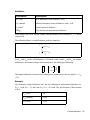
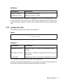
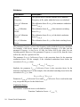
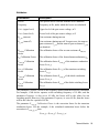
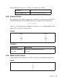
OUT Nodes
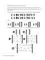
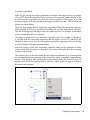
Nodes that pass the values from JMAG to PSIM
The number of input and output nodes may vary, depending on the actual number of
input/output nodes in a particular circuit.
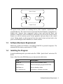
The MagCoupler block accepts voltages, currents, and positions as inputs, and it
provides voltages, currents, positions, torques, and force as the outputs. In PSIM, the
MagCoupler block is a power circuit element. The way it interfaces with the rest of the
circuit is that both the inputs and outputs are voltage signals (no electric current flows
into the input node). To convert a branch current into a voltage signal, or vice versa, one
can use a current-controlled voltage source, or voltage-controlled current source.
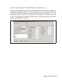
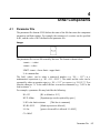
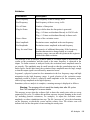
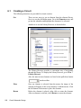
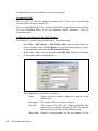
The Link Table File, in XML format, defines the input/output interface and corresponding functions in JMAG. This file is generated automatically by JMAG. To locate this
file, click on the browse button
at the right of the edit field.
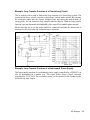
The JMAG Input File is the JCF input data file that is read by the JMAG solver. The
name is defined in the Link Table File.
Note that JCF input file .jcf must be in the same directory as the input link table file
.xml. If any material database is used in JMAG, it should also be placed in the directory
of the .xml file. Also, the .xml file does not have to be in the same directory as the
schematic file. However, if a .xml file with the same name is present in the schematic
directory, PSIM will read the one in the schematic directory first.
The JMAG Case Text is a text identifying the specific JMAG circuit. It can be any text
describing the JMAG circuit.
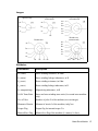
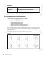
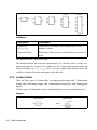
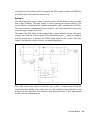
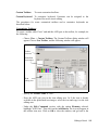
The IN Nodes are the nodes through which PSIM passes the values to JMAG. In the
MagCoupler block image, the order of the input nodes is from the top to the bottom. The
order can be changed by highlighting the node and click on the upper or down arrow.
The OUT Nodes are the nodes through which JMAG passes the values back to PSIM. In
the MagCoupler block image, the order of the output nodes is from the top to the
bottom. The order can be changed by highlighting the node and click on the upper or
down arrow.
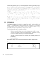
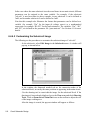
By clicking on the Edit Image button, one can edit and customize the image of the
MagCoupler block. Clicking on the Display File button will display the Link Table File
in the Microsoft Internet Explorer environment, and clicking on the Read File button
will read or re-load the Link Table File.
Set-up in JMAG and PSIM:
Using the MagCoupler block, it is easy to set up the link between JMAG and PSIM for
co-simulation. It involves two main steps: setting up the circuit in JMAG and generating
MagCoupler Module
91