1
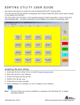
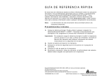
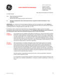
O P E R AT I N G I N S T R U C T I O N S Use these Operating Instructions to assemble and use the 6054 Network Control Module and the 6055 Docking Module. The 6054 Network Control Module controls one to four 6055 Docking Modules, which provides Pathfinder® 6057 printer charging and Ethernet communication capability The 6054 Network Control Module and the 6055 Docking Module can only be used with printers that contain the approved battery as listed in the printer documentation. Refer to the Operator’s Handbook for additional important battery safety information. Follow the operating and storage limit specifications listed at the end of these instructions. Otherwise, the battery may permanently lose its charge capacity. Note: You must charge the printer before using it. 6054 Netw ork Control Module TC6054OI Rev. AA 5/11 6055 Docking Modules ©2010 Avery Dennison Corp. All rights reserved. Assembling the Network Control Module 1. Turn over the 6055 Docking Module and 6054 Network Control Module. 2. Using a Philips screwdriver, remove the end cap from the Network Control Module. End Cap Netw ork Control Module 3. Using a Philips screwdriver, loosen two screws on the 6055 Docking Module and slide the connector plate under the screws. Tighten the screws. Connector Plate Docking Module Netw ork Control Module 2 4. Loosen the two screws on the 6054 Network Control Module and slide the 6054 Network Control Module onto the Docking Module’s connector plate. Tighten the screws. End Cap 5. Using a Philips screwdriver, attach the end cap to the end of the 6055 Docking Module. 6. Carefully turn over the Network Control Module. You can connect up to four Docking Modules with each Network Control Module. Repeat steps 3 – 6 for each additional Docking Module. Make sure you attach the end cap to the final Docking Module. 3 Setting up the Network Control Module 1. Plug the supplied power cable into the Network Control Module. 2. Plug the other end of the cable into a grounded electrical outlet. The green power LED on the 6054 Network Control Module turns on. Communication Cable goes here 3. Connect the communication cable from the host to the Network Control Module. 4 Reading the Ethernet LEDs When the communication port is connected, two LEDs indicate the following: Green LED Yellow LED LED ON OFF Blinking Yellow Full Duplex Mode Half Duplex Mode NA Green Active Ethernet Link NA Receiving/Transmitting data Charging the Battery Charge the battery while it is inside the printer. Slide the printer into the Docking Module until you hear a click. Pow er LED 5 The green power LED on the 6054 Network Control Module turns on when there is power to it. Charging time can take up to three hours. It takes approximately 1 hour to reach the 80% level (where it is now usable). To reach 100%, it takes approximately 2 hours more. Reading the Display Charging LED – flashes when you insert the printer; on (solid) during charging; off when charging is complete. Complete LED – flashes when the printer’s battery is 80% charged; on (solid) when the battery is 100% charged. Note: The Charging and Complete LEDs are ON continuously when updating the printer’s firmware while on the Docking Module. Do not remove the printer or disconnect power to the Docking Module at this time. Troubleshooting When an error occurs, the Charging and Complete LEDs blink together. In this case, repeat the charging process. If the error still occurs, put a new battery into the printer and place the printer back into the charger. If there is a problem after the second attempt to charge, call Service. In between charges, remove the printer, wait for the lights to stop flashing, then re-insert the printer. If you experience communication problems while charging, check the Ethernet LEDs. See “Reading the Ethernet LEDs” for more information. 6 Specifications Operating Limits: Temperature Humidity 32°F to 104°F (0°C to 40°C) 5% to 90% non-condensing Storage Limits: Temperature Humidity -40°F to 158°F (-40°C to 70°C) 5% to 90% non-condensing One Docking Module Length: 8.6” (218 mm) Width: 4.75” (121 mm) Height: 3.4” (86 mm) Weight: 1.7 lbs. (0.7 kg) Shipping Weight: 2.2 lbs. (1 kg) Network Control Module Length: 7” (178 mm) Width: 3.5” (89 mm) Height: 2.25” (57 mm) Input: 12 to 16 VDC/50W Weight: 2.2 lbs. (1 kg) Shipping Weight: 2.7 lbs. (1.2 kg) Power Supply Input: Universal switching power supply, 85 to 264 VAC, 50/60 Hz. Output: 12 VDC/80W max 7 8