1
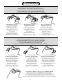
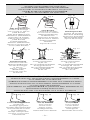
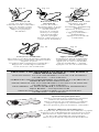
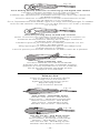
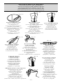
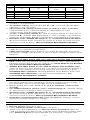
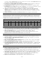
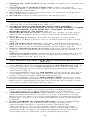
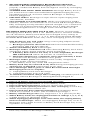
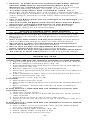
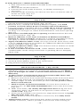
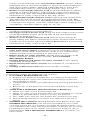
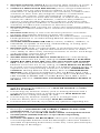
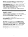
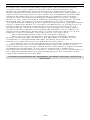
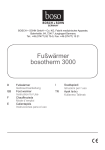
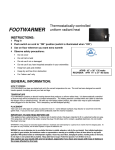
OPERATING INSTRUCTIONS
MODE D’EMPLOI
GEBRAUCHSANWEISUNG
ISTRUZIONI D’USO
BRUKSANVISNING
INSTRUCCIONES OPERADORAS
08/09
ATTACHING BATTERY PACKS
FIXATION DU BLOC-PILES
BEFESTIGUNG DES AKKU-PACKS
FISSAGGIO DELL’UNITÀ BATTERIE
MONTERING AV BATTERIPAKETET
SUJECIÓN DEL PAQUETE DE BATERÍAS
Fig. 1
Attaching to back
of Power Strap
Fixation à l’arrière
de la courroie
Befestigung hinten
am Halteriemen
Fissaggio posteriore
sul nastro
Montering bak på
Kardborrebandet
Sujeción a la parte
posterior de la correa
Fig. 2
Attaching to front
of Power Strap
Fixation à l’avant
de la courroie
Befestigung vorne
am Halteriemen
Fissaggio anteriore
sul nastro
Montering fram på
kardborrebandet
Sujeción a la parte
delantera de la correa
Fig. 3
Do not attach to
slippery surfaces
Ne pas fixer aux
surfaces glissant
Nicht an rutschigen
Oberflächen anbringen
Non attaccare su
superfici lisce
Montera den inte
på hala ytor
No sujetar en superficies
deslizantes
POSITIONING BATTERY PACK
POSITIONNEMENT DU BLOC-PILES
POSITIONIERUNG DES AKKU-PACKS
POSIZIONE DELL’UNITÀ BATTERIE
BATTERIPAKETETS POSITION
COLOCACIÓN DEL PAQUETE DE BATERÍAS
Fig. 4
Positioning
Battery Pack HIGH
Positionnement
HAUT du bloc-piles
Positionierung des
Akku-Packs HOCH
Posizione ALTA
dell’unità batterie
Batteripaketets
position är HÖG
Colocación ALTA del
paquete de baterías
Fig. 5
Positioning
Battery Pack LOW
Positionnement BAS
du bloc-piles
Positionierung des
Akku-Packs TIEF
Posizione BASSA
dell’unità batterie
Batteripaketets
position är LÅG
Colocación BAJA del
paquete de baterías
Fig. 6
Positioning
Battery Pack FRONT
Positionnement À
L’AVANT du bloc-piles
Positionierung des
Akku-Packs VORNE
Posizione FRONTALE
dell’unità batterie
Batteripaketets position
är FRAMME
DELANTERA del
paquete de baterías
Fig. 7
Positioning Battery Pack on LATERAL SIDE
Positionnement LATÉRAL du bloc-piles
Positionierung des Akku-Packs SEITLICH
Posizionamento LATERALE del blocco batteria
Batteripaketets position är på SIDAN
Colocación del paquete de baterías en el LATERAL
-1-
ADDITIONAL ATTACHMENT ACCESSORIES
AUTRES ACCESSOIRES DE FIXATION
ZUSÄTZLICHES BEFESTIGUNGSZUBEHÖR
ACCESSORI SUPPLEMENTARI PER IL FISSAGGIO
YTTERLIGARE MONTERINGSTILLBEHÖR
OTROS ACCESORIOS DE FIJACIÓN
Fig. 8
Fig. 10
Fig. 9
Slide Strap Bracket
Fixation de montage
à la courroie en Velcro®
(Slide Bracket)
Akku Pack-Halterung für
Klettriemen (Slide Bracket)
Dispositivo di fisaggio
sulla fascetta in Velcro®
(Slide Bracket)
Förslutningsbands
.klammer (Slide Bracket)
Soporte en el lateral de la
correa (Slide Bracket)
Strap Bracket
Fixation de montage
à la courroie en Velcro®
Akku Pack-Halterung
für Klettriemen
Dispositivo di fisaggio
sulla fascetta in Velcro®
Förslutningsbands
.klammer
Soporte de correa
Mounting Bracket
Fixation de montage
Akku-Pack Halterung
Dispositivo di fissaggio
Monteringsklämmor
Soporte de montaje
Fig. 13
Fig. 11
Velcro®
Attachment Strap
Courroie en Velcro®
Klettverschlußriemen
Fascetta di fissaggio
in Velcro®
Velcro® – remmar
(Kardborrlås)
Correa de sujeción
de Velcro®
Fig. 12
80 cm Extension Cord
Cordon prolongateur
de 80 cm
80 cm Verlängerungskabel
Prolunga da 80 cm
80 cm förlängningssladd
Cable prolongador
de 80 cm
120 cm Extension Cord
Cordon prolongateur
de 120 cm
120 cm Verlängerungskabel
Prolunga da 120 cm
120 cm förlängningssladd
Cable prolongador
de 120 cm
APPLYING FOOTWARMER CUSTOM TO CUSTOM INSOLES
APPLICATION DU CHAUFFE-PIEDS FOOTWARMER CUSTOM
AUX SEMELLES SUR MESURE
ANBRINGEN DES FOOTWARMER CUSTOM AUF MASSEINLAGEN
APPLICAZIONE DELLO SCALDAPIEDI FOOTWARMER CUSTOM
SU PLANTARI ORTOPEDICI
MONTERING AV FOOTWARMER CUSTOM PÅ DEN INDIVIDUELLA
INLÄGGSSULANINLÄGGSSULAN
APLICACIÓN DEL CALIENTAPIÉS A LA SUELA INTERIOR
Fig. 14
Correct heating position
Position de
chauffage appropriée
Korrekte Heizungsposition
Posizionamento corretto
di riscaldamento
Korrekt värmeposition
Posición correcta para
calentamiento
Fig. 15
Too far forward
Trop à l’avant
zu weit vorne
Troppo avanti
för långt framme
Demasiado hacia delante
-2-
Fig. 16
Too far back
Trop à l’arrière
zu weit hinten
Troppo indietro
för långt bak
Demasiado hacia atrás
Fig. 17
Fig. 18
Make a narrow slit
Faire une fente étroite
Schmalen Schlitz schneiden
Fare un intaglio stretto
Klipp en smal springa
Haga una pequeña
hendidura
Fig. 19
Run Power Cord
through slit
Passer le cordon
électrique dans la fente
Anschlußkabel durch
Schlitz führen
Inserire il cordone
elettrico nel taglio
Led strömsladden
genom springan
Pase el cable eléctrico a
través de la hendidura
Fig. 20
Trim excess Cambrelle®
Découper l’excédent de bande Cambrelle®
Überschüssiges Cambrelle® Wegschneiden
Tagliare la parte
eccedente del rivestimento Cambrelle ®
Klipp bort överflödigt Cambrelle®
Corte el exceso de Cambrelle®
Apply Cambrelle® cover
Appliquer une ban
de Cambrelle®
Cambrelle®- Stoffüberzug
auflegen
Applicare il rivestimento
Cambrelle®
Lägg på Cambrelle® –
beklädnaden
Aplique una funda de
Cambrelle®
Fig. 21
Apply Cambrelle® strip
Appliquer la bande Cambrelle®
Cambrelle®-Streifen anbringen
Applicare il nastro Cambrelle®
Sätt på Cambrelle® – remsan
Aplique una tira de Cambrelle®
APPLYING FOOTWARMER CUSTOM TO HOTRONIC’S
HEAT READY INSOLES
INSTALLATION DU FOOTWARMER CUSTOM SUR SEMELLES
HOTRONIC – HEAT READY
ANBRINGEN DES FOOTWARMERS CUSTOM AUF HOTRONIC’S
HEIZFERTIGE SCHUHEINLAGEN
APPLICAZIONE DEL FOOTWARMER CUSTOM SULLE SOLETTE
HOTRONIC – HEAT READY
MONTERING AV FOOTWARMER CUSTOM PÅ HOTRONICS
HEAT READY – INLÄGGSSULOR
APLICACIÓN DEL CALIENTAPIÉS A LAS PLANTILLAS
HOTRONIC – HEAT READY
Fig. 22
Fig. 23
Open Heating Element door
Ouvrir l’ouverture pour l’élément chauffant
Öffnen der Heizelement Öffnung
Aprire l’apertura per l’elemento riscaldante
Öppna öppningen för värmeelementet
Abra la apertura para el elemento calentador
Remove adhesive-separating-layer
Ôter la pellicule de séparation autocollante en papier
Entfernen der selbstklebenden Papiertrennschicht
Rimuovere lo strato adesivo divisorio di carta
Ta bort det självhäftande papperskiktet
Retire la película de separación del adhesivo
-3-
Fig. 24
Insert Heating Element with Power Cord facing up and aligned with channel
Introduire l’élément chauffant avec le câble vers le haut,
suivre le sillon prévu pour l’installation du câble
Einführen des Heizelementes mit Kabel und Chip nach oben und in der Flucht
der Kabelvertiefung
Inserire l’elemento riscaldante con il cavetto d’alimentazione rivolto
verso l’alto ed allineato con la scanalatura
För in värmeelementet med sladden uppåt och i linje med fördjupningen för sladden
Inserción del elemento calentador con el cable eléctrico cara arriba y alineado
con el canal
Fig. 25
Close door pressing firmly on both sides of insole
Fermer l’ouverture pour l’élément chauffant en pressant fortement sur
les deux côtés de la semelle
Schliessen der Heizelement Öffnung durch kräftiges Andrücken
auf beiden Seiten der Einlage
Chiudere l’apertura per l’elemento riscaldante, premendo con forz
su ambo i lati della soletta
Stäng öppningen för värmeelementet genom att kraftigt trycka
på båda sidorna av inlägget
Cierre la apertura presionando firmemente en ambos lados de la plantilla
Fig. 26
Apply Cambrelle© strip
Introduire la bande autocollante Cambrelle©
Anbringen des selbstklebenden Cambrelle© Streifens
Applicare il nastro autoaderente in tessuto Cambrelle
Sätt på det självhäftande Cambrelle skicktet
Aplique la tira Cambrelle©
Trim to size
Couper la semelle à la pointure désirée
Auf richtige Grösse zuschneiden
Tagliare la soletta alla misura giusta
Klipp till riktig storlek
Corte al tamaño deseado
Fig. 27
Semi Custom – Heat Ready Insoles
Semelles Semi Custom – Heat Ready
Semi Custom – Heizfertige Schuheinlage
Plantare Semi Custom – Heat Ready
Semi Custom – Heat Ready Insoles
Plantillas Semi Custom – Heat Ready
Fig. 28
One Size Fits All – Heat Ready Insoles
Semelles – Heat Ready – One Size
Zuschneidbare, heizfertige Schuheinlage
Plantare – Heat Ready – One Size
One Size Fits All – Heat Ready Insoles
Plantillas Heat Ready en tamaño único
-4-
INSTALLATION OF INSOLES
INSTALLATION DES SEMELLES
INSTALLATION DER HEIZSOHLEN
INSTALLAZIONE DELLE SOLETTE
MONTERING AV INLÄGGSSULAN
INSTALACIÓN DE LAS PLANTILLAS
Fig. 31
Fig. 30
Fig. 29
Position and cut T-slit
Placer et découper
la fente en T
In der korrekten Position
T-Schlitz schneiden
Effettuare l’intaglio a T nella
corretta posizione
Klipp en T – formad
springa i den rätta
positionen
Coloque y corte una
hendidura en T
Run Power Cord
Free floating channel
through T-slit
Canal flottant libre
Passer le cordon électrique
Freilaufkanal
dans la fente T
Canalina per il
Anschlußkabel durch
cordone
elettrico
T-Schlitz führen
Fritt löpande kanal
Inserire il cordone elettrico
Canal flotante libre
nell’intaglio a T
Led strömsladden
genom T – springan
Pase el cable eléctrico por la
hendidura en T
Fig. 32
Fig. 33
Fig. 34
Free floating channel
Canal flottant libre
Freilaufkanal
Canalina per il
cordone elettrico
Fritt löpande kanal
Canal flotante libre
Excessive Power
Cord exposed
Trop de cordon
électrique exposé
Zu viel Anschlußkabel
freiliegend
Cordone elettrico
eccessivamente esposto
För mycket kabel
ligger fritt
Excesivo cable eléctrico expuesto
Folded & splayed
Power Cord
Cordon électrique
replié et aplati
Zusammengelegtes
und gespreiztes Kabel
Cordone elettrico
piegato e divaricato
Ihoprullad kabel
Cable eléctrico
plegado y separado
Folded & splayed
Power Cord
Cordon électrique
replié et aplati
Zusammengelegtes
und gespreiztes Kabel
Cordone elettrico
piegato e divaricato
Ihoprullad kabel
Cable eléctrico
plegado y separado
Fig. 35
Free floating channel
Canal flottant libre
Freilaufkanal
Canalina per il
cordone elettrico
Fritt löpande kanal
Canal flotante libre
Adequate Power Cord exposed
Suffisamment de cordon
électrique exposé
Genug (aber nicht zu
viel) Anschlußkabel
freiliegend
Cordone elettrico
adeguatamente esposto
Lagom (men inte för
mycket) kabel ligger fri
Suficiente cable eléctrico expuesto
Fig. 36
-5-
Placing folded
Power Cord
Passer le cordon
électrique replié
Einlegen des
zusammengelegten
Anschlußkabels
Posizionamento del
cordone elettrico piegato
Iläggning av den
ihoprullade kabeln
Colocación del cable
eléctrico plegado
•
•
•
•
•
•
•
•
•
•
•
•
•
•
•
•
•
•
•
•
•
•
•
•
•
•
•
•
•
TABLE OF CONTENTS
CONTENTS IN BOX
OVERVIEW
TEMPERATURE & DURATION CHART
OPERATING BATTERY PACK SETTINGS
BATTERY PACK LED LIGHTS (LEDs)
EXCESS HEAT ON ANY SETTING, INCLUDING OFF
USING HEAT SETTINGS
WHAT TO EXPECT OF HEAT SETTINGS
COMFORT & WARMTH RANGES
TIPS ON BATTERY PACK OPERATING TEMPERATURES
TIPS ON USING FOOTWARMER
DRY BOOTS! DRY SOCKS!
ATTACHING BATTERY PACKS
POSITIONING BATTERY PACKS
RECHARGING BATTERY PACKS
WHAT TO EXPECT OF BATTERY PACKS
TIPS ON RECHARGING
TIPS ON SUMMER & LONG TERM STORAGE
INSTALLING HEATING ELEMENTS IN HOTRONIC’S HEAT READY
INSOLES
INSTALLING HEATING ELEMENTS ON CUSTOM INSOLES
INSTALLING INSOLES IN GENERAL FOOTWEAR
INSTALLING INSOLES IN BOOTS WITH REMOVABLE LINERS
TIPS ON INSTALLATION
OTHER MISCELLANEOUS TIPS
CAUTIONS REGARDING BURNS
CAUTION: USE HOTRONIC BRAND COMPONENTS ONLY
CAUTIONS REGARDING RECHARGING
CAUTIONS
HOTRONIC LIMITED WARRANTY
CONTENTS IN BOX
FootWarmer CUSTOM Power Plus m4 and Power Plus m3 both
contain:
• 2 Battery Packs with Integrated Heat Regulator
• 1 Pair of Heating Elements with Self-Adhesive Fabric Covers and
Strips
• 1 Recharger (global input 100-240VAC, 50/60Hz) with North
American and European Plug Adapters
• Operating Instructions & Limited Warranty Card
OVERVIEW
The Hotronic FootWarmer is dedicated to your foot wherever it goes
and easily transfers from one type of footwear to another. Based on
computer technology, Battery Pack’s micro-controller permits four (4)
temperature-duration settings. High quality, rechargeable NiMH
batteries are selected for cold temperature performance. Heating
Elements locate directly under toes. Recharger globally accepts input
ranging from 100-240VAC, 50/60Hz. Following temperatures and
durations are approximations only as ratings are affected by recharging
process and various tolerances of batteries and electronics. Durations
are determined when Battery Packs are used in ambient temperature of
-4°F (-20°C).
-6-
Set.
1
2
3
4
TEMPERATURE & DURATION CHART
Approx. Avg. Temp. Range
Duration Range
Power Plus
Power Plus
°C
°F
m4
m3
28°-32°
83°-89°
19-21 hrs
15-17 hrs
36°-41°
96°-106°
7-9 hrs
5.5-7 hrs
40°-47°
105°-116°
5-6.5 hrs
3.5-5 hrs
57°-62°
135°-144°
2.5-3.75 hrs
2-3 hrs
OPERATING BATTERY PACK SETTINGS
1. To turn on or off, press-and-hold ON or OFF until LED light is ON
or OFF (~2.0 seconds).
2. To change setting, press-and-hold ◄ or ► until setting LED light
changes (~0.5 seconds).
3. Once selected, setting 4 auto-resets to setting 3 after 3 minutes
(“timed setting 4”). (“Timed setting 4” LED lights are ON
continuously and do NOT blink.)
4. To use “continuous setting 4”, start at “timed setting 4”, then press
and hold ► until all LED lights blink (~5.0 seconds). (“Continuous
setting 4” LED lights BLINK continuously until setting is changed.)
5. DO NOT USE “TIMED SETTING 4” or ”CONTINUOUS SETTING
4” for more than three minutes at a time as it may become too hot
and may result in burns. SEE CAUTIONS REGARDING BURNS.
BATTERY PACK LED LIGHTS (LEDs)
1. Battery Pack LEDs indicate power is on or off and setting selected.
LEDs do not indicate charge level.
2. LEDs will not light when batteries are fully discharged, are below
minimum voltage cutoff level, or do not have enough power to heat
Element.
EXCESS HEAT ON ANY SETTING, INCLUDING OFF
1. WHEN BATTERY PACK LED stays ON and CANNOT BE TURNED
OFF, water may be around electrical contacts, may cause Heating
Element to become hot at any setting, and MAY RESULT IN BURNS.
See CAUTIONS REGARDING BURNS.
2. WHEN BATTERY PACK IS ON ANY SETTING, INCLUDING OFF,
and you feel your foot getting hot, you think you might be getting a
burn, or you experience any early warning sensations of a burn,
IMMEDIATELY UNPLUG Heating Element from Battery Pack and
IMMEDIATELY REMOVE your foot from FootWarmer. See
CAUTIONS REGARDING BURNS.
USING HEAT SETTINGS
1. Use FootWarmer to maintain comfort and warmth. (Note: Prevent
feet from getting cold. Warming cold feet requires more energy, is
less effective, and is not intended use of FootWarmer.)
2. Before going into cold, set at 1, 2, or 3 to maintain comfort and
warmth.
3. For additional burst of heat, set to “timed setting 4”. “Timed setting
4” auto-resets to setting 3 after 3 minutes.
4. DO NOT USE “TIMED SETTING 4” or ”CONTINUOUS SETTING
4” for more than three minutes at a time as it may become too hot
and may result in burns. SEE CAUTIONS REGARDING BURNS.
5. Heat does not thermostatically cycle on and off. Settings 1 and 2
maintain warmth AND save energy.
1.
2.
3.
4.
WHAT TO EXPECT OF HEAT SETTINGS
Expect imperceptible heat to maintain comfort and warmth.
Do not expect “fireplace toes”.
Learn what personally works best over time.
Think of your FootWarmer as Thermo Active Insulation (TM). As
cold penetrates through insole, it draws heat off Element rather than
toes. Balanced heat is imperceptible yet maintains comfort and
-7-
5.
6.
7.
8.
9.
warmth. Too much heat and feet feel excess heat. Too little heat and
feet feel cold penetrating through.
If feet are comfortable yet feel excess heat, turn to lower setting to
minimize perspiration and maximize battery duration.
If feet begin to feel cool, turn setting up to maintain comfort and
warmth.
If you think FootWarmer is not working, try turning left Battery Pack
off. If left foot becomes colder, FootWarmer is working.
Ability to feel heat and maintain comfort and warmth depends
upon: proper installation; type, fit, and dryness of footwear, sock,
and insole; foot callus size; activity levels; weather conditions; and
other factors.
Expect bottom of toes to feel heat less than fingers and hands.
COMFORT AND WARMTH RANGES
When first learning use of FootWarmer, following chart may help in
setting selection. Chart represents approximate ranges for comfort and
warmth maintenance. First determine outside temperature then select
setting based on personal sensitivity to cold. More sensitive select left of
range. Less sensitive select right..
°
Setting
1
2
3
C
F
COMFORT AND WARMTH RANGES
OUTSIDE TEMPERATURES
>0
0
-4
-7 -10 -12 -15
>32
32 25 20 15 10
5
•
•
•
•
•
•
•
•
•
•
•
•
•
•
•
-18
0
-21
-5
•
•
TIPS ON BATTERY PACK OPERATING TEMPERATURES
1. When going into temperatures below freezing (where Battery Packs
may be exposed), turn Battery Packs minimally to setting ONE as
this protects batteries from freezing and any harm that may occur
due to freezing.
2. Do not operate Battery Packs that have been OFF and in
temperatures below freezing as it may harm batteries and cause
Battery Packs to function improperly or not at all.
TIPS ON USING FOOTWARMER
1. Extremely poor circulation or extremely cold conditions may
require setting 2 or 3 for comfort and warmth. Extra Battery Packs
extend all day comfort and warmth.
2. Do not allow chair lift to hit you! Damage may result to you and
your FootWarmer.
3. Be careful walking down stairs! Battery Packs may catch stair edge
when mounted on back of boots.
4. Place heated insole (fabric surface up) directly underneath socked
foot. Do not place another insole over heated insole.
5. Proper fitting boots help maintain comfort and warmth. Tight boots
and improper fit restrict blood flow and compromise comfort and
warmth.
DRY BOOTS! DRY SOCKS!
1. If boots and socks are wet, expect cold feet.
2. Wet conductive heat loss is 23 times greater than dry heat loss. (W.
L. Gore & Associates, 1994)
3. Feet perspire more than any other part of your body except your
head and hands. Each foot perspires about 1/4 cup of water a day at
rest and one full cup when active. (W. L. Gore & Associates, 1994)
4. Maintain dry boots! Dry after each use! Each additional day of
moisture buildup makes warm feet more difficult. Consider boot
dryer (i.e., Hotronic’s Snapdry Boot & Glove Dryer).
5. Remove inner boots to dry between liner and boot shell.
-8-
6. Maintain dry, clean socks! Change midday for afternoon comfort and
warmth.
7. Use single pair of medium weight socks. Select wool blend,
polypropylene®, or thermax® type socks to wick moisture away and
keep feet dry and warm.
8. Do not use thick socks, neoprene socks, or reflective sock liners as
these keep heat from toes.
9. Do not use cotton or other moisture absorbing socks.
ATTACHING BATTERY PACKS (Fig. 1-3, 8-13)
1. Slide Battery Pack Wire Clip SECURELY over boot top (see point 2
below), boot or shoe laces, or attach to strap such as Velcro® power
strap on ski or snowboard boot. (Fig. 1-2)
2. NOTE: DO NOT SLIDE BATTERY PACK OVER SLIPPERY
MATERIAL SUCH AS SKI BOOT PLASTIC AS THE EASIER IT SLIDES
ON, THE EASIER IT WILL SLIDE OFF. SECURELY ATTACH
BATTERY PACK AT ALL TIMES. (Fig. 3)
3. Mounting Bracket Accessory (optional). For simple, secure, quick
attachment of Battery Packs to ski or hard shell snowboard boots.
(Fig. 10)
4. Strap Bracket Accessory (optional). For simple, secure, quick
attachment of Battery Packs to ski or snowboard boot power straps.
(Fig. 9)
5. Slide Strap Bracket Accessory (optional). For Battery Pack Power
Plus m4 and m3 only. Provides simple, secure, quick attachment of
Battery Packs to ski or snowboard boot power straps. (Fig. 8)
6. Velcro® Attachment Strap Accessory (optional). Strap around leg at
or above calf or around boot top. Battery Pack clips over Strap.
(Fig. 11)
7. Extension Cord Accessory (optional). Run Cord underneath pant leg
and plug into Battery Pack at waist height (80 cm Cord) or chest
height (120 cm Cord). (Fig. 12-13)
1.
2.
3.
4.
POSITIONING BATTERY PACKS (SKI & SNOWBOARD BOOTS)
(Fig. 4-7)
Positioning Battery Pack HIGH on back of boot permits pant leg to
cover Battery Pack but increases potential chair lift damage. (Fig. 4)
Positioning Battery Pack LOW on back of boot reduces potential
chair lift damage but increases potential damage while walking
down stairs. (Fig. 5)
Positioning Battery Pack on TOP FRONT of boot permits pant leg to
cover Battery Pack, eliminates potential chair lift and stair damage,
and is convenient when adjusting setting. (Fig. 6)
Positioning Battery Pack on TOP LATERAL SIDE of boot (see Strap
Bracket and Slide Strap Bracket drawings) permits pant leg to cover
Battery Pack, eliminates potential chair lift and stair damage, and is
convenient when adjusting setting. (Fig. 7)
RECHARGING BATTERY PACKS
• CAUTION - WARRANTY: Use Hotronic’s White Plug Recharger
ONLY for Power Plus m4 and Power Plus m3 Battery Packs. Using
other than Hotronic’s White Plug Recharger voids Warranty.
• CONDITIONING CHARGE: When Battery Pack is new or has not
been used for more than 2 months, it is very important to charge
Battery Pack for 48 to 72 hours uninterrupted. Conditioning Charge
brings new, unused, or unconditioned Battery Pack to full capacity
potential.
• FULLY CHARGED IN 3 HOURS OR LESS: Hotronic’s White Plug
Recharger detects when Battery Pack is fully charged and
automatically switches to trickle current recharging after
approximately 3 hours or less of full current recharging. Fully
charged, properly conditioned Battery Pack reaches full capacity
potential. Fully charged, unconditioned Battery Pack does NOT
reach full capacity potential. (See Conditioning Charge.)
-9-
• RECOMMENDED OVERNIGHT RECHARGING PROCESS:
Hotronic’s Recommended Recharging Process helps maintain
properly conditioned Battery Pack throughout season by recharging
overnight.
• SUMMER AND LONG TERM STORAGE: Recharge Battery Pack as
per instructions for Recommended Overnight Recharging Process,
turn Battery Pack off, and store without Recharger or Heating
Element plugged in.
• ELECTRIC INPUT: Recharger accepts electric input ranging from
100-240VAC, 50-60Hz.
• OCCASIONAL FULL DISCHARGE: While not required of NiMH
batteries, Hotronic recommends an occasional full discharge before
fully recharging to help maintain optimal strength. Use “continuous
setting 4” for quickest discharge. Battery Pack is fully discharged
when Heating Element is no longer warm and all LEDs are off.
RECHARGE WHEN BATTERY PACK IS OFF: Hotronic recommends
recharging when Battery Pack is off. (Battery Pack is off when all LEDs
are off.) However, Battery Pack MAY be recharged at any setting. If
recharging while on setting 1, 2, 3, or 4, DO NOT CHANGE SETTING
DURING RECHARGING as this may cause recharging process to stop.
1. Plug Recharger into wall outlet using correct plug adapter (North
American, European, or other).
a. Recharger performs short self-test with brief red LED followed by
brief green LED and then LED off.
2. Attach each Battery Pack to Recharger.
3. Recharger LED is continuous red when detecting Battery Pack status
and during initial current and full current recharging.
a. If Battery Pack status is not okay or is not compatible, Recharger
LED will blink red within 20 minutes of continuous red.
b. Maximum duration for continuous red is approximately 3 hours
at which time Recharger LED becomes green.
4. Recharger LED is green once Battery Pack is fully charged and
indicates trickle current recharging.
a. One Battery Pack may reach full charge before other.
5. Battery Pack may be removed at any time during recharging process
and may be re-attached to Recharger at any time.
6. Once Recharger LED is green or when Recommended Overnight
Recharging Process is complete:
a. Unplug Battery Pack from Recharger.
b. Unplug Recharger from wall outlet.
7. To maintain maximum charge after recharging, turn Battery Pack off
and store without Recharger or Heating Element plugged in.
1.
2.
3.
4.
5.
6.
7.
8.
WHAT TO EXPECT OF BATTERY PACKS
Expect all battery types to lose strength over time.
Expect optimal performance of newer Battery Packs.
Expect optimal performance with use shortly after recharging.
Expect less than optimal performance after recharging as each day,
week, or month passes before use.
Expect much less than optimal performance from Battery Packs
stored for 2 months or more. (See Conditioning Charge.)
Battery self-discharge rates may range from 1 to 3 percent per day.
When Battery Packs are unplugged and left on settings 1, 2, 3, or 4,
a slight increase in discharge results.
When unplugging Recharger from wall outlet, also unplug Battery
Packs from Recharger. When not unplugged, damage may occur to
Recharger and a slight increase in Battery Pack discharge may occur
regardless of setting.
TIPS ON RECHARGING
1. When Recharger green LED is on (trickle current recharging), Battery
Pack may remain on Recharger indefinitely.
- 10 -
2. However, as further protection against possible battery damage,
Hotronic DOES NOT recommend leaving Battery Pack on
Recharger for extended periods of time such as 24 hours (except
during Conditioning Charge), one week, or one month.
3. To confirm wall outlet is NOT controlled by switch, plug in
Recharger, attach Battery Pack, and confirm continuous red LED
status. Recharger’s red LED is on continuously when outlet current is
active and goes off within seconds when outlet is turned off by
switch.
4. One or two Battery Packs may be recharged on one Recharger per
above instructions.
5. One Power Plus m4 Battery Pack and one Power Plus m3 Battery
Pack may be recharged simultaneously on same Recharger.
6. Hotel room razor outlets (and other Ground Fault Current
Interrupter outlets) are not recommended.
TIPS ON SUMMER & LONG TERM STORAGE
1. For summer and long term storage, recharge Battery Pack as per
Recommended Overnight Recharging Process instructions, turn
Battery Pack off, and store without Recharger or Heating Element
plugged in.
2. Prior to use after summer and long term storage, perform Battery
Pack Conditioning Charge for 48 to 72 hours uninterrupted.
3. Do not store (or keep overnight) Battery Pack at temperatures
above 105°F (40°C) as this will harm batteries.
4. Do not store (or keep overnight) Battery Pack at temperatures at or
below freezing (32°F) (0°C) as it may harm batteries.
5. Do not store (or keep overnight) Recharger at temperatures below 4°F (-20°C) or above 149°F (65°C) as this may harm Recharger.
INSTALLING HEATING ELEMENTS IN HOTRONIC’S HEAT READY
INSOLES (Fig. 22-28)
Installing Heating Elements in Hotronic’s HEAT READY INSOLES
(models ONE SIZE FITS ALL INSOLES and SEMI-CUSTOM INSOLES)
1. Open Heating Element door found on bottom of Insole. (Fig. 22)
2. Remove adhesive separating layer. (Fig. 23)
3. Insert Heating Element with Power Cord facing up and aligned
with channel. (Fig. 24)
4. Remove adhesive cover layer on Heating Element.
5. Close door pressing firmly on each side of Insole to set adhesive.
(Fig. 25)
6. Apply self-adhesive fabric strip over Heating Element door and
Power Cord channel. (Fig. 26)
7. Trim Insole to size. (Fig. 27-28)
CAUTION:
1. DO NOT CUT Power Cord.
2. DO NOT CUT Heating Element located inside Heating Element
door.
3. Place red fabric, heated side of Insole up when installing in
footwear.
If using Hotronic’s ONE SIZE FITS ALL INSOLES in footwear with
removable insoles:
1. Align tips of both insoles.
2. Trace removable insole on backside of Hotronic Insole around
sides and heel.
3. Trim Hotronic Insole to size of removable insole.
4. Hotronic Insole may be placed on top of removable insole or in
place of.
If using Hotronic’s ONE SIZE FITS ALL INSOLES in footwear without
removable insoles:
1. Trace outline of foot on backside of Insole with TOES aligned
over top of Heating Element.
2. Cut Insole along sides and heel. (Fig. 28)
3. Select slightly larger sizing line at first.
4. Further trim Insole where necessary.
- 11 -
If using Hotronic’s SEMI CUSTOM INSOLES:
1. First select best size SEMI CUSTOM Insole and install Heating
Element.
2. Place Insole inside footwear.
3. If Insole fits well inside footwear, no further trimming is
necessary.
4. If Insole needs trimming, use trim-to-size lines on bottom side of
Insole toe area. (Fig. 27)
5. Trim Insole as needed.
1.
2.
3.
4.
5.
6.
7.
8.
1.
2.
3.
4.
INSTALLING HEATING ELEMENTS ON CUSTOM INSOLES
(Fig. 14-21)
With foot on custom insole, position Heating Element under toes
placing Power Cord toward heel. (Fig. 14-16)
Remove foot, carefully lift Heating Element slightly, and mark
position on insole where Power Cord descends from Element.
Use razor knife or grinding device to make slit or narrow opening at
marked position. Hard insole material may require wider opening
for Plug. Use heat gun to soften hard material for narrowest opening.
(Fig. 17)
Run Power Cord through slit or opening until Element lies flat and
in correct position. (Fig. 18)
Remove adhesive cover layer on bottom of Element and adhere
Element in correct position. If Element is without self-adhesive layer,
use spray or brush-on adhesive between insole and Element.
Apply self-adhesive fabric cover over top of insole. Trim excess with
scissors AFTER applying. If needed, use additional adhesive between
insole and fabric. (Fig. 19-20)
Apply self-adhesive fabric strip over Power Cord on bottom of insole
to hold in place. (Fig. 21)
If foot is sensitive to Power Cord, create shallow channel where
needed under insole using razor knife or grinding device. Reapply
fabric strip.
INSTALLING INSOLES IN GENERAL FOOTWEAR
(Fig. 14-28)
Place insole in footwear with Power Cord flat underneath.
Run Power Cord up back or side of leg.
Securely fasten Battery Pack as per instructions.
Plug Power Cord into Battery Pack.
INSTALLING INSOLES IN BOOTS WITH REMOVABLE LINERS
(Ski & Snowboard Boots…) (Fig. 29-36)
1. Pay complete attention during installation to prevent chafing,
abrading, cutting, over tension, and tearing of Power Cord. These
types of damages are NOT covered under Manufacturer’s Limited
Warranty.
2. To place Power Cord between inner boot (removable liner) and
shell, Hotronic recommends following:
a. Remove inner boot from shell and existing insole from inner boot.
b. With insole removed, use fingertips along bottom inside and
outside edges of inner boot heel pocket to locate position where
Power Cord will exit.
c. Mark 3/4 inch (2cm) horizontal line on inner boot exterior at
position for cut. DO NOT POSITION CUT over inner boot seam.
(Fig. 29)
d. With razor knife, cut cleanly through inner boot along 3/4 inch
(2cm) line. Then cut 3/8 inch (1cm) up from center of line to
create T-slit. (Fig. 29)
e. Insert insole partially into inner boot, align Power Cord, and push
Plug through T-slit. (Fig. 30)
f. Verify Power Cord is laying flat in inner boot, then fully insert
insole.
3. Taping Power Cord to inner boot may protect it from undue wear
and tear. However, reduce possible over tension and severing of
- 12 -
Cord in forward flexing with “free floating channel” in tape. Adhere
half-width strip of duct tape lengthwise up center of full width piece
with sticky sides together. With full width adhered to inner boot,
half-width strip serves as “free floating channel”. (Fig. 31-32)
4. Reduce excess length of Power Cord by gently folding into ribbon,
splaying to reduce thickness, and taping in center. Place between
inner boot and shell. DO NOT BEND REPEATEDLY in previously
folded area as it may cause Cord to fail. (Fig. 34-36)
5. Leave adequate length of Power Cord looped up and outside boot.
This reduces chances of tearing and damaging Power Cord. Too
short becomes inconvenient. Too long exposes unnecessary lengths
to damage from zippers, chair lifts, metal edges (when stepping out
of bindings), and other objects. (Fig. 33, 35, 36)
TIPS ON INSTALLATION
1. For specific footwear or activities, contact your Hotronic Dealer
regarding installation recommendations.
2. For longer reach of Power Cord, bring out from under insole in front
of outside anklebone then up along side of leg. (For Equestrian
Dressage or Field boots.)
3. Reduce excess length of Power Cord for liner-less footwear by
gently folding into ribbon and taping in center. Position folds closely
outside top of footwear. DO NOT BEND REPEATEDLY in previously
folded area as it may cause Cord to fail.
OTHER MISCELLANEOUS TIPS
1. All Hotronic FootWarmers within a given model essentially have
same total energy output. Tolerances in micro-controllers, microprocessors, micro-chips, and batteries result in any setting being
slightly warmer while not lasting as long and vice versa.
2. Battery Packs are water resistant. Should water get inside, hold,
shake, and place upside down until dry. See CAUTIONS
REGARDING BURNS.
3. Heating Elements and Insoles are water resistant. If wet, drying
completely prolongs life.
4. Replacement parts and accessories are available at your Hotronic
Dealer.
5. Sending in Warranty Card helps insure proper coverage.
CAUTIONS REGARDING BURNS
Use of Hotronic FootWarmer may result in burns. The higher the
temperature setting, the higher the risk of burns.
• IT IS USER’S RESPONSIBILITY TO:
• Properly use Hotronic FootWarmer according to Instructions.
• Understand his or her own individual sensitivity to heat and
susceptibility to burns.
• Understand his or her own individual early warning sensations of
a burn.
• Remove his or her feet from source of heat before a burn may
occur.
• SOME EARLY WARNING SENSATIONS OF A BURN are:
• When any area of your feet becomes hot.
• When any area of your feet feels like you are standing on a small
pebble or pointed object and may or may not feel hot.
• The colder one’s feet are, the sharper the sensation may feel.
• Early warning sensations of a burn may differ from person to
person.
• IMMEDIATELY UNPLUG Heating Element from Battery Pack and
IMMEDIATELY REMOVE your foot from FootWarmer if you feel
your foot getting hot, if you think you might be getting a burn, or if
you experience any early warning sensations of a burn. Do not reuse
FootWarmer until you are certain your foot is no longer at risk of
being burned. SEE A PHYSICIAN IMMEDIATELY if you think you
have a burn.
- 13 -
• DO NOT USE heat setting 4 for more than three minutes at a time. It
may become too hot for continuous use and may result in burns.
• CONSULT WITH YOUR PHYSICIAN prior to using FootWarmer if
you might have any physiological condition or are using any
medication or drug which increases skin sensitivity or reduces skin
sensation to heat. Such physiological condition or medication
increases risk of burns. Some physiological conditions or
medications which increase skin sensitivity or reduce skin sensation
to heat are calluses on feet, diabetes, cardiovascular problems,
nervous system disorders, Raynaud’s syndrome, and tetracycline.
Other physiological conditions or medications which increase skin
sensitivity or reduce skin sensation to heat may exist.
• DO NOT WAIT until your feet are cold to turn temperature setting
up because cold feet reduce skin’s sensation to heat and increase risk
of burns.
• DO NOT USE damp or wet socks because presence of moisture
increases heat transfer and may increase risk of burns.
• DO NOT USE Hotronic Heating Element (1) without fabric covering
Heating Element or (2) with Heating Element directly exposed on
surface of insole.
• NOT RECOMMENDED FOR USE by infants, toddlers, children, or
individuals incapable of knowing, understanding, or acting upon
early warning sensations of a burn.
• DO NOT USE while consuming drugs or alcohol because these may
increase skin sensitivity, reduce skin sensation to heat, or reduce
one’s ability to detect early warning sensations of a burn. Such drugs
or alcohol may increase risk of burns.
• DO NOT USE while sleeping.
• WATER AROUND ELECTRICAL CONTACTS may cause Heating
Element to become hot at any setting and MAY RESULT IN BURNS.
• WHEN BATTERY PACK LED stays ON and CANNOT BE TURNED
OFF, water may be around electrical contacts, may cause Heating
Element to become hot at any setting, and MAY RESULT IN BURNS.
If you feel your foot getting hot, think you might be getting a burn, or
experience any early warning sensations of a burn, IMMEDIATELY
UNPLUG Heating Element from Battery Pack and IMMEDIATELY
REMOVE your foot from FootWarmer. Dry out Battery Pack, plug
area, and Heating Element plug. Do not use again until Battery Pack
LED CAN BE TURNED OFF. Consider Battery Pack LED a water
presence indicator. MAINTAIN CAUTION REGARDING BURNS at
all times.
CAUTION: USE HOTRONIC BRAND COMPONENTS ONLY
• DO NOT USE any non-Hotronic branded, look-alike components
with the Hotronic FootWarmer as it MAY BE UNSAFE and MAY
RESULT IN BURNS.
• Connecting any Hotronic battery pack or heating element with a
non-Hotronic battery pack or heating element MAY RESULT IN
BURNS at any setting including “0” (off).
• Connecting any Hotronic battery pack or recharger with a nonHotronic battery pack or recharger MAY BE UNSAFE.
• Contact Hotronic directly if you have any questions regarding this.
CAUTIONS REGARDING RECHARGING
• Recharger is FOR INDOOR USE ONLY.
• Recharger is INTENDED FOR CORRECT ORIENTATION AND
CONNECTION to power outlet at all times.
• Recharger is intended FOR USE ONLY WITH rechargeable Nickelmetal-hydride (NiMH) batteries as specified in Operating
Instructions.
• DO NOT ATTEMPT TO RECHARGE other types of rechargeable or
non-rechargeable batteries with this Recharger (other than NiMH as
specified in Operating Instructions) as this may cause personal injury
and damage to Recharger.
- 14 -
• KEEP DRY. TO PREVENT FIRE OR ELECTRICAL SHOCK, do not
expose this unit to rain or moisture.
• DO NOT OPERATE THIS RECHARGER with damaged plug.
• DO NOT REPAIR OR ATTEMPT TO REPAIR Recharger, Battery
Pack, or any other Hotronic branded electrical unit, component part,
or accessory in any situation.
• NOT INTENDED FOR USE by young children or infirm persons
without supervision.
• SUPERVISE YOUNG CHILDREN to ensure they do not play with
Recharger and / or any component part or accessory of FootWarmer.
• WHEN THERE IS AN EMERGENCY CASE, immediately unplug all
Battery Packs from Recharger and unplug Recharger from power
outlet. Contact Hotronic distributor or dealer.
• SOME EMERGENCY CASES are smoke coming from Recharger,
shape change, liquid or material leakage, and unit dropped and
broken. Other emergency cases may exist.
CAUTIONS
• ATTACH BATTERY PACK SECURELY at all times as loss of Battery
Pack is NOT covered under Manufacturer’s Limited Warranty.
• SETTING 4 HAS INCREASED IN TEMPERATURE (as of 7/95) and
MAY RESULT IN BURNS.
• USE OF FOOTWARMER DOES NOT ASSURE that freezing or
frostbite of foot will not occur. As always, use caution and good
judgment when you are in cold temperatures.
• DO NOT CAUSE ELECTRICAL LEADS in plug area of Battery Pack to
touch as there is DANGER OF A SHORT CIRCUIT.
• DO NOT USE FOOTWARMER IF ANY BATTERY PACK
ELECTRICAL LEADS ARE BENT such that any two leads may contact
upon further use. Such contact may cause an increase in temperature
output of Heating Element and MAY RESULT IN BURNS or such
contact may result in a SHORT CIRCUIT.
• DO NOT DAMAGE Battery Pack by use of undue external force.
• DO NOT DISPOSE of Battery Pack by throwing in a fire as there is
DANGER OF EXPLOSION.
• DO NOT PUT ANY METAL OBJECTS into plug area of Battery Pack
as there is DANGER OF A SHORT CIRCUIT.
• DO NOT CAUSE UNDUE OR EXCESSIVE WEAR, TEAR, OR
ABRASION to Power Cord as there is DANGER OF A SHORT
CIRCUIT.
• INSPECT ALL RECHARGER AND HEATING ELEMENT POWER
CORDS for exposed wires prior to plugging into Battery Packs or
electrical outlet as exposed wires may result in a SHORT CIRCUIT.
• DO NOT WRAP RECHARGER OR HEATING ELEMENT POWER
CORDS AROUND BATTERY PACKS while plugged into Battery
Packs as this may result in a SHORT CIRCUIT.
• DO NOT PLUG RECHARGER PLUG INTO BATTERY PACK
BACKWARDS as there is DANGER OF A SHORT CIRCUIT.
• DO NOT CUT Power Cord or Heating Element.
• DO NOT KINK Power Cord or Heating Element.
• BATTERY PACK MAY CONTAIN HAZARDOUS MATERIALS and
may require specific disposal. Contact Hotronic distributor or dealer
or local recycling agency for proper disposal method.
- 15 -
HOTRONIC LIMITED WARRANTY
The Hotronic® FootWarmer Power Plus carries a limited warranty
for three (3) years from the date of purchase. This limited warranty
extends only to the original consumer who purchased the new
Hotronic® FootWarmer Power Plus from an authorized Hotronic®
dealer. Dated Proof of Purchase is required. Hotronic® will replace or
repair only that component of the Hotronic® FootWarmer Power Plus
found to be defective as to workmanship or material. This limited
warranty does not extend to damage resulting from misuse, neglect,
abuse, or any use inconsistent with the operating instructions; normal
wear and tear; changes in exterior appearance or color; breakage
(except breakage resulting from manufacturing defects); improper dealer
service; improper dealer or consumer modifications to product; loss of
product due to improper attachment; any normal variations in the
temperature per setting or the duration per charge per setting which
results from the method of recharging the batteries, the conditions in
which the FootWarmer Power Plus is used, and the tolerances of the
batteries, micro-controller, micro-processor, or micro-chip.
This Limited Warranty is the only warranty offered.
There are no other warranties, expressed or implied. Neither
Hotronic International Limited nor the Distributor is liable for any
incidental or consequential damages resulting from the use or
possession of the Hotronic® FootWarmer Power Plus.
If a defect arises in the FootWarmer Power Plus within the limited
warranty period, the user should promptly return the product to an
authorized Hotronic® dealer. Dated Proof of Purchase is required. If the
FootWarmer Power Plus or any other component is replaced or
repaired, the replacement or repair is covered only for the remainder of
the original Limited Warranty period dating from the purchase of the
original FootWarmer Power Plus.
Contact nearest Hotronic distributor if yellow warranty card is not
enclosed.
- 16 -
HOTRONIC INTERNATIONAL LTD.
Worldwide Distributors
AUSTRALIA
L.A. Imports
Unit 8 / 1 Vuko Place
Warriewood N.S.W. 2102
Phone: 00 61 (0)2 9913 7155
Fax: 00 61 (0)2 9913 3177
e-mail: [email protected]
GERMANY
Hotronic Deutschland
Waldstrasse 24
D-82205 Gilching
Phone: 00 49 (0)8105 26 051
Fax: 00 49 (0)8105 26 031
e-mail: [email protected]
AUSTRIA
Hotronic Deutschland
Waldstrasse 24
D-82205 Gilching
Phone: 00 49 (0)8105 26 051
Fax: 00 49 (0)8105 26 031
e-mail: [email protected]
GREAT BRITAIN
Manby International
Sportswear
Milner Road
Sudbury, Suffolk CO10 2XG
Phone: 0044 (0)1787 881 144
Fax: 0044 (0)1787 880 072
e-mail: [email protected]
web page: www.hotronic.co.uk
BELGIUM
Aquatic Benelux BVBA
Ooststraat 33 C
B-9961 Boekhoute
Phone: 00 32 474 60 15 45
Fax: 00 32 (0)9 373 55 03
e-mail: [email protected]
CANADA
Hotronic Canada Inc.
30154 Twp. Rd. 250
Calgary, Alberta T3Z 1L5
Phone: 011 800 690 9998
Phone: 001 403 288 3667
Fax: 001 403 247 2997
e-mail: [email protected]
CZECH REPUBLIC
Burda-Sport s.r.o.
Železnicáru 204/6
170 00 Praha 7
Phone: 00 420 (2) 6671 0751
Fax: 00 420 (2) 2087 8320
e-mail:
[email protected]
FINLAND
Henrik Granholm OY
Ounasvaarantie 5 D 55
FIN-00970 Helsinki
Phone: 00 358 40 08 00 070
Fax: 00 358 9 32 56 372
e-mail: [email protected]
FRANCE
Ricochet Access
ZA Les Ruires-3b rue Joliot
Curie
F-38320 Eybens
Phone: 0033 (0)438 24 09 45
Fax: 0033 (0)438 24 09 49
e-mail:
[email protected]
HUNGARY
Veterinarius 2000 Kft.
Esterházy A. u. 12
H-9700 Szombathely
Phone: 0036 94 501 371
Fax: 0036 94 501 372
e-mail: [email protected]
ICELAND, DENMARK,
GREENLAND
Elnet Taekni ehf
Audbrekku 16
IS-200 Kopavogur
Phone: 00 354 554 2727
Fax: 00 354 554 2728
e-mail: [email protected]
ISRAEL
Safety Systems Lt”d.
P.O.B. 887
RAMAT GAN 52108
Phone: 00 972 (0)3 6315675
Fax: 00 972 (0)3 6355351
e-mail: [email protected]
ITALY
VIST S.r.l.
Via Paludi di Caldaro 15
I-39052 Caldaro s.S.d.V. (BZ)
Phone: 00 39 0471 810062
Fax: 00 39 0471 802273
e-mail: [email protected]
LATVIA
Stélnieks – A SIA
Baznicas iela 39
Riga, LV –1010
Phone: 00371 7291913
Fax: 00371 7315574
e-mail: [email protected]
NEW ZEALAND
Bobo Products Ltd.
5 Ross Street
P.O. Box 43
Darfield 8172
Canterbury
Phone: 00 64 (0)3 317 9096
Fax: 00 64 (0)3 317 9095
e-mail: [email protected]
NORWAY
Wintersteiger Norge
Postboks 173
N-1556 Son
Phone: 0047 64 95 95 95
Fax: 0047 64 95 95 85
e-mail: [email protected]
PRINCIPAT D’ANDORRA
Oxigen Distribucións SL.
C/Hort de Godi, 1 2°-2a
AD200 Encamp (Principat
d’Andorra)
Phone: 00 376 83 25 60
Fax: 00 376 83 25 62
e-mail: [email protected]
RUSSIA
Apiko-Fish Ltd.
Pankratyevskyi per, 2
107045 Moscow
Phone: 00 7 (0)495 234 3184
Fax: 00 7 (0)495 956 6739
e-mail: [email protected]
web page: www.apico-fish.ru
SPAIN
Jausun Import Export S.L.
c/Jaume I, 2
E-25660 Alcoletge
Phone: 00 34 973 19 62 38
Fax: 00 34 973 19 62 77
e-mail: [email protected]
SWEDEN
Åre Agentur AB
Årevägen 55/Box 160
S-830 13 Åre
Phone: 00 46 (0)647 52 210
Fax: 00 46 (0)647 52 209
e-mail: [email protected]
SWITZERLAND
BS Trading AG
Riedloeserstrasse 5
CH-7302 Landquart
Phone: 00 41 (0)81 330 00 80
Fax: 00 41 (0)81 330 00 82
e-mail: [email protected]
UNITED STATES OF AMERICA
Hotronic USA, Inc.
P.O. Box 908
25 Omega Drive
Williston, VT 05495
Phone: 001 802 862 7403
Fax: 001 802 863 6519
e-mail: [email protected]
web page: www.hotronic.com
PATENTED
© 2008 Copyright Hotronic International Ltd.
Printed in China