1
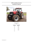
GPS AutoSteer System
Installation Manual
Supported Vehicles
CNH
Case
Accuguide
New Holland
Intellisteer
MX-210
MX-230
TG-210
TG-215
MX-255
MX-285
TG-230
TG-245
MX-215
MX-245
TG-255
TG-275
MX-275
MX-305
TG-285
TG-305
T8010
T8020
T8030
T8040
MX-335
T8050
PN: 602-0224-01-A
LEGAL DISCLAIMER
Note: Read and follow ALL instructions in this manual carefully before installing or operating the AutoSteer system.
Note: Take careful note of the safety information in the Safety Information section and throughout this manual.
The manufacturer disclaims any liability for damage or injury that results from failure to follow the instructions and warnings
set forth herein.
Please take special note of the following warnings:
1. There is NO obstacle avoidance system included in the manufacturer’s product. Therefore, users must always have an
operator on the equipment when the AutoSteer system is in use to look for any obstacles including people, animals, trees,
ditches, buildings, etc.
2. During installation of the AutoSteer system and during the Calibration and Tuning processes the vehicle's wheels turn from
side to side and the vehicle moves. Be sure that all people and obstacles are clear of the vehicle before installation, calibration and tuning, or use of the AutoSteer system.
3. Use of the AutoSteer system is NOT permitted while the vehicle is on public roads or in public areas. Ensure that the system is OFF before driving on roads or in public areas.
ii
AutoSteer System
Special Requirements
Tools
This list consists of the tools required to complete the installation. The installer is assumed to have a complete set of common
installation tools.
Allen Hex Key 1/4”
11/16” open wrench
16mm open wrench
Allen Hex Key 3/16”
5/8” open wrench
17mm open wrench
Allen Key 5/32”
9/16” open wrench (2x)
18mm open wrench
Allen Hex Key 1/8”
1/2” open wrench
19mm open wrench
15/16” open wrench
7/16” open wrench
22mm open wrench
7/8” open wrench
15/16” socket wrench
24mm open wrench
13/16” open wrench
13mm open wrench
#1 Phillips screwdriver
3/4” open wrench
Wire cutter small
#2 Phillips screwdriver
Cleaning brush
Tape measure (12ft minimum)
Cleaning rags
10 Foot Ladder
Fiberglass Cable Puller
Hardware Installation Guide
iii
Safety Information
Warning Alerts
The AutoSteer system installer and manufacturer disclaim any responsibility for damage or physical harm caused by failure to
adhere to the following safety requirements:
•
•
As the operator of the vehicle, you are responsible for its safe operation.
The AutoSteer system is not designed to replace the vehicle’s operator.
Note: Verify all screws, bolts, nuts, and cable connections are tight after the final installation of the AutoSteer system on
the vehicle.
WARNING
To avoid electrical shock hazards, remove the Roof Module
from the vehicle before driving under low structures or low
electrical power lines.
WARNING
To prevent injury from falling, ensure you are in a stable
position on the vehicle when installing or removing the Roof
Rail and Roof Module. If the vehicle does not provide a safe
platform, use a ladder to safely access the vehicle roof while
installing or removing the Roof Rail and Roof Module.
WARNING
To prevent accidental death or injury from being run over by
the vehicle, never leave the vehicle's operator chair with the
AutoSteer system engaged.
iv
AutoSteer System
WARNING
To understand the potential hazards associated with the
operation of AutoSteer system equipment read the provided
documentation before installing the AutoSteer system on a
vehicle.
WARNING
To prevent the accidental engagement of AutoSteer and loss
of vehicle control while driving on roads, shut down the
AutoSteer system (exit the program). Never drive on roads
or in public areas with the AutoSteer system turned on.
Hardware Installation Guide
v
Caution Alerts
The AutoSteer system installer and manufacturer disclaim any responsibility for damage or physical harm caused by failure to
adhere to the following safety requirements:
CAUTION
The Roof Module must be removed when transporting or
driving the vehicle at speeds above 30 mph (50 km/h). The
Roof Module can possibly detach due to wind loads at
higher speeds.
CAUTION
The AutoSteer system does not detect obstacles in the
vehicle’s path. The operator must observe the path being
driven in order to avoid obstacles.
CAUTION
When engaged, the AutoSteer system controls only the
steering of the vehicle. The operator must control the speed
of the vehicle.
CAUTION
The AutoSteer system must be powered OFF when
installing or removing the Roof Module.
vi
AutoSteer System
CAUTION
The AutoSteer system must be powered OFF when starting
or cranking the vehicle’s engine.
CAUTION
The Roof Module must always be firmly secured to the Roof
Rail using the hardware whenever the vehicle is in operation
to prevent the Roof Module from releasing from its bracket
and falling.
Vehicle Requirements
The vehicle steering system must be in good working order before installing the AutoSteer system. Check for loose or worn
parts. Before installing the AutoSteer system drive the vehicle and confirm that it steers straight and the wheels can be turned
from lock to lock. Check the steering system connections to ensure there are no oil leaks.
The vehicle electrical system and battery must be in good working order.
The vehicle should be fully cleaned before installing the AutoSteer system. A clean vehicle will improve the overall
installation and cable routing.
This installation kit is designed for tractors that are 'steer ready' from the factory so the tractor must be equipped with an
AutoSteer valve on the Steering Orbitrol and a kingpin angle sensor.
Hardware Installation Guide
vii
Important Information
Note: Verify all screws, bolts, nuts, and cable connections are tight after the final installation of the AutoSteer system on the
vehicle.
Technical Support
Refer to your Display user manual for technical support information.
Contact Information
Refer to your Display user manual for contact information.
Copyright © 2009 All Rights Reserved.
viii
AutoSteer System
Table of Contents
Chapter 1
Installation Overview....................................................................................... 1
Vehicle Inspection . . . . . . . . . . . . . . . . . . . . . . . . . . . . . . . . . . . . . . . . . . . . . . . . . . . . . . . . . . . 1
Kit Components . . . . . . . . . . . . . . . . . . . . . . . . . . . . . . . . . . . . . . . . . . . . . . . . . . . . . . . . . . . . . 2
Installation Procedure Outline . . . . . . . . . . . . . . . . . . . . . . . . . . . . . . . . . . . . . . . . . . . . . . . . . . 3
Cable Diagram . . . . . . . . . . . . . . . . . . . . . . . . . . . . . . . . . . . . . . . . . . . . . . . . . . . . . . . . . . . . . . 4
Chapter 2
SA Module Installation..................................................................................... 5
SA Module Mounting Orientation . . . . . . . . . . . . . . . . . . . . . . . . . . . . . . . . . . . . . . . . . . . . . . 6
Mount the SA Module Bracket . . . . . . . . . . . . . . . . . . . . . . . . . . . . . . . . . . . . . . . . . . . . . . . . . 6
Mounting the SA Module on Older Vehicles . . . . . . . . . . . . . . . . . . . . . . . . . . . . . . . . . . . . 7
Mounting the SA Module on Newer Vehicles . . . . . . . . . . . . . . . . . . . . . . . . . . . . . . . . . . . 8
Chapter 3
Roof Module Installation ................................................................................ 11
Safety Notes . . . . . . . . . . . . . . . . . . . . . . . . . . . . . . . . . . . . . . . . . . . . . . . . . . . . . . . . . . . . . . . 11
Roof Rail Installation . . . . . . . . . . . . . . . . . . . . . . . . . . . . . . . . . . . . . . . . . . . . . . . . . . . . . . . . 12
Chapter 4
Display Installation ........................................................................................ 17
Introduction . . . . . . . . . . . . . . . . . . . . . . . . . . . . . . . . . . . . . . . . . . . . . . . . . . . . . . . . . . . . . . . 17
Installation Procedure . . . . . . . . . . . . . . . . . . . . . . . . . . . . . . . . . . . . . . . . . . . . . . . . . . . . . . . 17
Chapter 5
Connecting System Cables............................................................................. 19
SA Module Harness . . . . . . . . . . . . . . . . . . . . . . . . . . . . . . . . . . . . . . . . . . . . . . . . . . . . . . . . . 19
SA Module Connection . . . . . . . . . . . . . . . . . . . . . . . . . . . . . . . . . . . . . . . . . . . . . . . . . . . . 20
Wheel Angle Sensor Connection. . . . . . . . . . . . . . . . . . . . . . . . . . . . . . . . . . . . . . . . . . . . . 22
Steering Valve Connections . . . . . . . . . . . . . . . . . . . . . . . . . . . . . . . . . . . . . . . . . . . . . . . . 26
Main Cable Harness . . . . . . . . . . . . . . . . . . . . . . . . . . . . . . . . . . . . . . . . . . . . . . . . . . . . . . . . . 35
Roof Module . . . . . . . . . . . . . . . . . . . . . . . . . . . . . . . . . . . . . . . . . . . . . . . . . . . . . . . . . . . . 36
Main Cable Harness Connections Inside Cab . . . . . . . . . . . . . . . . . . . . . . . . . . . . . . . . . . . 39
SA Module Harness . . . . . . . . . . . . . . . . . . . . . . . . . . . . . . . . . . . . . . . . . . . . . . . . . . . . . . . 40
Power Supply Connection . . . . . . . . . . . . . . . . . . . . . . . . . . . . . . . . . . . . . . . . . . . . . . . . . . . . 40
Cab Power Connection . . . . . . . . . . . . . . . . . . . . . . . . . . . . . . . . . . . . . . . . . . . . . . . . . . . . 41
Battery Power Connection . . . . . . . . . . . . . . . . . . . . . . . . . . . . . . . . . . . . . . . . . . . . . . . . . . 41
Chapter 6
Post-Installation Procedures and Information .................................................... 43
Create New Vehicle . . . . . . . . . . . . . . . . . . . . . . . . . . . . . . . . . . . . . . . . . . . . . . . . . . . . . . . . . 43
Calibration and Tuning Guidelines . . . . . . . . . . . . . . . . . . . . . . . . . . . . . . . . . . . . . . . . . . . . . 43
Transducer Calibration . . . . . . . . . . . . . . . . . . . . . . . . . . . . . . . . . . . . . . . . . . . . . . . . . . . . 43
Chapter 7
Final Hardware Installation Checklist ............................................................... 45
Hardware Installation Guide
ix
x
AutoSteer System
1
Installation Overview
This Installation Overview chapter contains part numbers, kit overview diagram, cabling diagram and the installation
procedure.
•
•
•
•
Vehicle Inspection
Kit Components
Installation Procedure Outline
Cable Diagram
This installation guide describes the installation of the AutoSteer system on several models of Case MX Accuguide ready and
New Holland TG IntelliSteer ready tractors. The installation kit PN: 188-0034-01 is used on both series of these wheeled
tractors.
Vehicle Inspection
Before you install the AutoSteer system, confirm the vehicle steering system is in good working order. Drive the vehicle and
verify the vehicle’s correct working order. Also, ensure the following system operations and components:
•
•
•
•
•
Check to see if you can turn the steered wheels from lock to lock.
Ensure the vehicle steers straight.
Check for loose or worn steering components.
Service the vehicle if the steering is not in good working order.
Confirm the tractor has the Accuguide valve and other components already installed.
Hardware Installation Guide
1
Kit Components
Figure 1-1
Kit Components (PN: 188-0034-01)
Table 1-1
Installation Kit Components (PN: 188-0034-01)
Item
Component
Part Number
1.
RAM Mount Double U-bolt
207-0010-01
2.
Mounting Hardware
200-0076-01
3.
Roof Module Adapter Brackets
200-0387-01
4.
Installation Guide
602-0224-01
5.
SA Module Assembly
200-0206-01
6.
SA Module Harness
201-0351-01
7.
Display Bracket Assembly
200-0190-01
8.
Common Installation Kit
200-0497-02
9.
Type A Harness Adapter
201-0405-02
2
AutoSteer System
Item
Component
Part Number
10.
Type B Harness Adapter
201-0407-02
11.
Warning Labels
603-0074-01
Installation Procedure Outline
Note: The system interconnect cable diagram in the Cable Diagram on page 4 section of this chapter shows the AutoSteer
electrical connections.
1. Verify that all components have been received.
Note: Step 2 and Step 5 are skipped if installing an electric steering actuator.
2. Install the SA Module.
3. Install the Roof Rail on the cab roof.
4. Install the Roof Module on the Roof Rail.
5. Install the SA Module Harness.
6. Install the Main Cable Harness.
7. Install the Display using a RAM Mount.
8. Connect the Main Cable Harness to the Display Harness.
Note: Instructions for connecting the vehicle kit cables to the Display can be found in the Display user manual.
9. Verify that all connectors are properly coupled and secured.
10. Power ON the AutoSteer system.
11. Calibrate the vehicle.
12. Tune the vehicle.
13. Verify the system has been installed properly and operates satisfactorily.
Hardware Installation Guide
3
Cable Diagram
4
AutoSteer System
2
SA Module Installation
This SA Module Installation chapter contains information in the following sections:
•
•
SA Module Mounting Orientation
Mount the SA Module Bracket
• Mounting the SA Module on Older Vehicles
• Mounting the SA Module on Newer Vehicles
Hardware Installation Guide
5
SA Module Mounting Orientation
The SA Module can also only be mounted in certain orientations. Figure 2-1 shows the correct mounting positions and
Figure 2-2 shows incorrect mounting positions.
Figure 2-1
Correct SA Module Mounting Orientations
Figure 2-2
Incorrect SA Module Mounting Orientations
Mount the SA Module Bracket
Due to the variety of options available on vehicles and the possible configuration differences, it may be necessary to install the
SA Module in a location other than the example shown here. If an alternative location is required, choose a location where the
SA Module can be protected from damage, from moving parts or crop debris, and excessive moisture from weather and
cleaning equipment.
There are two procedures for mounting the SA Module bracket. One for older vehicles and the second for newer vehicles.
•
•
6
Mounting the SA Module on Older Vehicles
Mounting the SA Module on Newer Vehicles
AutoSteer System
Mounting the SA Module on Older Vehicles
1. Mount the SA Module bracket on the right rear-side fender. See Figure 2-3.
Figure 2-3
SA Module Mounting Location
SA Module Mounting Bracket Bolt Locations
2. Mount the SA Module to the bracket and secure using four Phillips screws. See Figure 2-4.
Note: The SA Module Harness was routed into the cab to connect to the Main Cable Harness. The other half of the
SA Module Harness is routed under the cab towards the Steering Valve and wheel angle sensor on the left side.
Hardware Installation Guide
7
Figure 2-4
SA Module Mounting Bracket Installed (shown with SA Module connector)
Mounting Screws
SA Module Mounted
Mounting the SA Module on Newer Vehicles
1. Remove the cover. See Figure 2-5.
Figure 2-5
Access Cover
Cover
8
AutoSteer System
2. Mounting the SA Module may require unmounting the relays shown in Figure 2-6.
Figure 2-6
Relay Locations
Relays
3. Mount the SA Module bracket in the position shown in Figure 2-7.
Figure 2-7
Mounting the SA Module Bracket
SA Module Bracket
4. Install the SA Module on the bracket and secure using four Phillips screws. Attach the SA Module Harness to the vehicle
harness. See Figure 2-8.
Hardware Installation Guide
9
Note: The SA Module Harness is routed into the cab to connect to the Main Cable Harness. The other half of the SA
Module Harness is routed under the cab towards the Steering Valve and wheel angle sensor on the vehicle’s left side.
Figure 2-8
SA Module Installed
SA Module Mounted
5. Zip-tie the relay tabs to the base of the SA Module Bracket as shown in Figure 2-9.
Figure 2-9
10
Zip-tie the Relay Tabs
AutoSteer System
3
Roof Module Installation
This Roof Module Installation chapter contains information in the following sections:
•
•
Safety Notes
Roof Rail Installation
Safety Notes
•
•
•
•
•
The steering system must be powered OFF when installing or removing the Roof Module.
The supplied locking pin must be in place whenever the vehicle is in operation.
The Roof Module must be removed when transporting the vehicle at speeds above 30 mph (50 km/h).
Ensure you are in a stable position on the tractor platform when removing the Roof Module, so that you do not fall or drop
the Roof Module.
Use a ladder to install the Roof Rail Brackets.
WARNING
Ensure that you are in a stable position on the vehicle when
installing or removing the Roof Rail and Roof Module so you
do not fall.
Hardware Installation Guide
11
Roof Rail Installation
1. Place the ladder as close as possible to the side of the cab.
Note: The ladder is necessary to install the Roof Rail and Roof Module.
2. Remove the four mounting nuts from the cab roof: two from the right and two from the left. See Figure 3-1.
Figure 3-1
Locate Mounting Nuts
Mounting Nuts
Cab Rear
3. Use the existing nuts to attach the two Roof Rail Brackets as shown in Figure 3-2 (two nuts per bracket).
Figure 3-2
Attach Roof Rail Brackets
Roof Rail Brackets
4. Center the Roof Rail on the cab roof.
12
AutoSteer System
5. Attach the Roof Rail using the bolts, nuts and washers supplied. Tighten securely with a 15/16” socket and ratchet and a
15/16” open wrench. See Figure 3-3.
Figure 3-3
Roof Rail Installed
Cab Front
6. Attach the three antennas to the proper Roof Module antenna connections. See Figure 3-4.
Note: Hand tighten the connections. Do not over tighten.
Figure 3-4
Attach the Antennas
WiFi Antenna
Cell Phone Antenna
RTK Modem Antenna
Hardware Installation Guide
13
7. Remove the Locking Pin from the Roof Rail. See Figure 3-5.
Note: Figure 3-5 shows the Roof Module already attached to the Roof Rail.
Figure 3-5
Remove Locking Pin
Locking Pin
8. Place the Roof Module on the Roof Rail. See Figure 3-6.
Figure 3-6
14
Attach Roof Module
AutoSteer System
9. Reinsert the Locking Pin into the Roof Rail. See Figure 3-5.
Note: The Locking Pin can be inserted from either side of the Roof Rail.
10. The completed Roof Module should appear as shown in Figure 3-6.
Hardware Installation Guide
15
16
AutoSteer System
4
Display Installation
This Display Installation chapter contains following Display information:
•
•
Introduction
Installation Procedure
Introduction
This chapter provides the instructions for installing the RAM Mount Ball in the cab so the Display can be attached later. Refer
to your Display user manual for instructions on installing the Display.
Installation Procedure
1. Locate the accessory mounting bracket on the right side of the cab. See Figure 4-1.
Note: Alternative mounting locations can be used if the location shown is not available.
Figure 4-1
Locate the Accessory Mounting Bracket
Accessory Mounting Bracket
Hardware Installation Guide
17
2. Insert the two U-bolts through the RAM Base, then place a nut on the end of the bolt threads (four nuts total).
3. Tighten the nuts evenly using a 10 mm socket and a 10 mm wrench. The resulting combination is shown in Figure 4-2.
Figure 4-2
Mounted RAM Ball
4. Place rubber caps on the end of the bolt threads.
Note: Refer to the Display user manual for the remaining Display-specific installation instructions.
18
AutoSteer System
5
Connecting System Cables
This Connecting System Cables chapter provides information for connecting the Main Cable Harness and the SA Module
Harness to the various vehicle and steering system components in the following sections:
•
•
•
SA Module Harness
• SA Module Connection
• Wheel Angle Sensor Connection
• Steering Valve Connections
• Steering Valve Location
• Steering Valve Connectors
• Pressure Transducer Connector
Main Cable Harness
• Roof Module
• Main Cable Harness Connections Inside Cab
• SA Module Harness
Power Supply Connection
• Cab Power Connection
• Battery Power Connection
SA Module Harness
This SA Module Harness section contains the following sub-sections:
•
•
•
SA Module Connection
Wheel Angle Sensor Connection
Steering Valve Connections
Hardware Installation Guide
19
SA Module Connection
1. Connect the SA Module Harness to the SA Module. See Figure 5-1.
Figure 5-1
Connecting SA Module Connector (different vehicle shown)
Bottom of SA Module
Cable Connector
Locking Mechanism in Open Position (Latch)
2. Close the cable connector locking mechanism as shown in Figure 5-2.
Figure 5-2
SA Module Connector (closed).
Locked Position
3. Route the SA Module Harness into the cab to connect to the Main Cable Harness. See Figure 5-3.
4. Route the other half of the SA Module Harness under the cab towards the Steering Valve and wheel angle sensor on the
left side. See Figure 5-3.
20
AutoSteer System
Figure 5-3
Routing the SA Module Harness from the SA Module
SA Module Harness Into Cab
SA Module Harness to Steering Valve
and Wheel Angle Sensor
5. Connect the 12-pin data and 2-pin power connectors between the Main Cable Harness and the SA Module Harness. See
Figure 5-4.
Figure 5-4
SA Module Harness to Main Cable Harness Connections
Hardware Installation Guide
21
Wheel Angle Sensor Connection
1. Locate the wheel angle sensor cable on the left side of front axle. The cable is protected by a plastic split loom cover. See
Figure 5-5.
Figure 5-5
Wheel Angle Sensor Connector Location
Plastic Split Loom Cover
2. Open the plastic cover and pull out the 6-pin connector. See Figure 5-6.
Note: Clean the connector before opening. Use a brush to remove loose dirt and a towel to remove water if necessary.
Figure 5-6
Accessing the Wheel Angle Sensor Connector
Wheel Angle Sensor Connector
22
AutoSteer System
3. Unplug the original vehicle harness from the short wheel angle sensor cable. See Figure 5-7.
Figure 5-7
Wheel Angle Sensor Connector Uncoupled
4. Connect the end of the “Y” connector with the single connector to the wheel angle sensor harness. See Figure 5-8.
Figure 5-8
Wheel Angle Sensor Harness Connection
Wheel Angle Sensor Harness Connector
Hardware Installation Guide
23
Note: You need to determine which “Y” adapter harness to use before starting the installation. The “Y” adapter
harness 201-0405-02 is used on standard axles. The “Y” adapter harness 201-0407-02 is used on supersteer axles.
Older tractors may not sense the error condition when the tractor wheel angle sensor connector is disconnected. In that
case, either “Y” cable hardware adapter can be used. You can check the installation by turning on the tractor after
installing the “Y” adapter and looking for the following fault codes on the pillar display: (See Figure 5-9)
• MFD Fault
• Difflock Fault
There are some inconsistencies with tractors that cause changes to the “Y” adapter installation. If you are getting one
of the error codes listed above and you’re using the correct “Y” adapter harness, start over and replace the “Y” adapter
harness with the opposite cable included in your kit.
Figure 5-9
Pillar Display Fault Messages
Difflock Fault
MFD Fault
5. Connect the two connectors on the opposite end of the “Y” harness to the SA Module Harness and the tractor harness. See
Figure 5-10.
Note: Ensure the connector labeled “Steering System” is connected to the SA Module Harness and the connector
labeled “Tractor” is connected to the tractor harness.
24
AutoSteer System
Figure 5-10 Wheel Angle Sensor “Y” Harness Connected
Wheel Angle Sensor Connector
Steering System Harness
Tractor Harness
6. Route the steering system harness through the existing plastic split loom cover. See Figure 5-11.
7. Secure all loose cables with cable ties. See Figure 5-11.
Note: Allow sufficient cable length for tie rod and axle movement when the vehicle is being steered.
Figure 5-11 Routing the Steering System Cable Harness
Hardware Installation Guide
25
Steering Valve Connections
This Steering Valve Connections section contains the following sub-sections:
•
•
•
Steering Valve Location
Steering Valve Connectors
Pressure Transducer Connector
Steering Valve Location
The Steering Valve is located on the left side of the tractor behind the air filter.
1. Pull on the plastic panel shown here to gain access to the Steering Valve. See Figure 5-12.
Note: The access to the Steering Valve may be different depending on the tractor model. On some tractors, you must
first open the engine hood to reach the Steering Valve.
Figure 5-12 Accessing the Engine Compartment
26
AutoSteer System
2. The Steering Valve is located to the top-right of the air filter. See Figure 5-13.
Figure 5-13 Steering Valve Location
Steering Valve
Hardware Installation Guide
27
3. There are two types of Steering Valves currently in use. Figure 5-14 shows the Steering Valve used on the older generation
MX-210 / 230 / 255 / 285 tractors.
Note: The newer generation MX-215 / 245 / 275 / 305 tractors use a different Steering Valve that is mounted directly
on the steering unit (Orbitrol).
Figure 5-14 MX-210/230/255/285 Tractor Steering Valve
28
AutoSteer System
4. Route the steering system harness with the three connectors shown here, passing under the cab.
Note: The three connectors should be routed until they are close to the Steering Valve.
Figure 5-15 SA Module Harness Steering Valve Connectors
2-pin Solenoid Connector
(used on new models only)
Note: The 2-pin solenoid connector shown in Figure 5-15 is only used on newer model vehicles. The connector is
shown connected to the Steering Valve in Figure 5-25.
Hardware Installation Guide
29
Steering Valve Connectors
1. Locate the 4-pin connector on the Steering Valve. See Figure 5-16.
Figure 5-16 Steering Valve 4-pin Connector
4-pin Connector
2. Unplug the original harness from the Steering Valve.
3. Cover the end of the original vehicle harness with the blind connector cap provided with the SA Module Harness.
Figure 5-17 Steering Valve 4-pin Connector Unplugged
30
AutoSteer System
4. Connect the 4-pin AutoSteer system connector to the Steering Valve. See Figure 5-18
Figure 5-18 Connecting the SA Module Harness 4-pin Connector
Pressure Transducer Connector
1. Locate the 3-pin connector on top of the Pressure Transducer on the Steering Valve. See Figure 5-19 and Figure 5-20.
Figure 5-19 Pressure Transducer Location
Pressure Transducer Connector
Hardware Installation Guide
31
Figure 5-20 Pressure Transducer Location (Rear View)
Pressure Transducer Located Behind Hose
2. Unplug the original harness from the Pressure Transducer. See Figure 5-21.
Note: The plastic latch must be released before you can pull off the connector.
Figure 5-21 Unplugging the Pressure Transducer Connector
32
AutoSteer System
3. Connect the 3-pin steering system connector to the Pressure Transducer on the Steering Valve. See Figure 5-22.
Figure 5-22 Connecting the SA Module Harness to the Pressure Transducer
SA Module Harness Connector
4. Figure 5-23 shows the SA Module Harness is connected to the Pressure Transducer.
Figure 5-23 SA Module Harness Connected to Pressure Transducer
SA Module Harness Connected
Hardware Installation Guide
33
Note: The 2-pin and 4-pin original connectors that were removed from the Steering Valve and solenoid must be
protected with a plug and secured to the tractor using cable ties. The connector removed from the Pressure Transducer
must be protected with a sheet of plastic secured with a cable tie. Secure the cables together in a protected position.
Figure 5-24 Original Steering Valve and Pressure Transducer Connectors
Note: Newer vehicle models have a solenoid valve on the Steering Valve side that must be connected. Figure 5-25
shows the valve that is factory installed on the newer MX tractors. This Steering Valve has an extra solenoid so it
requires connecting one more connector from the SA Module Harness.
34
AutoSteer System
Figure 5-25 Steering Valve Solenoid Valve (new models only)
2-pin Solenoid Connector
Main Cable Harness
This Main Cable Harness section contains the following sub-sections:
•
•
•
Roof Module
Main Cable Harness Connections Inside Cab
SA Module Harness
Hardware Installation Guide
35
Roof Module
1. Route the cable out the rear of the cab window through the rubber panel in the lower right corner of the rear window and
secure with cable ties. See Figure 5-26.
Figure 5-26 Main Cable Harness Exiting the Vehicle Cab
36
AutoSteer System
2. Attach the cable to the Roof Module. See Figure 5-27.
Orient the 12-pin connector so the word “TOP” on the cable connector is pointing upwards (towards the sky). Insert the
cable connector into the Roof Module. Push the connector in until it “clicks” and locks in place. To remove, grasp the
connector to compress the two side latches and pull away from the Roof Module.
Note: Do not force the connector. If the connector does not engage easily, check for the correct orientation of the
connector.
Figure 5-27 Roof Module Main Cable Harness Connection
Hardware Installation Guide
37
3. Attach the LAN connector to the Roof Module. See Figure 5-28.
Orient the Ethernet cable connector with the connector under the receiver so the contacts on the cable connector are
pointing towards the back of the vehicle. (This will usually be towards your right side if you are standing on the left side of
the vehicle and looking towards the Roof Module.) Slide the cable connector into the receiver and rotate the plastic
bayonet sleeve clockwise to lock the connector. The bayonet sleeve will “click” when it fully engages and locks. To
remove the cable, rotate the bayonet sleeve counterclockwise until it “clicks” and pull the connector down or away from
the Roof Module.
Note: Do not force the connector. If the connector does not engage easily, check for the correct orientation of the
connector.
Figure 5-28 Roof Module Ethernet Connection
38
AutoSteer System
Main Cable Harness Connections Inside Cab
Figure 5-29 shows the Main Cable Harness connections used inside the cab. Table 5-1 shows the functions of the Main Cable
Harness cab connectors. Refer to your Display user manual for instructions on connecting the Main Cable Harness
connections shown to the correct ports and harnesses on the Display and Display cables.
Figure 5-29 Main Cable Harness Cab Connections
Table 5-1
Cab Main Cable Harness Connector Functions
Main Cable Harness Connector
Connector Function
DISPLAY ETH
Display Ethernet Port (RJ-45)
DISPLAY COMM
Display Communication Port (DB-9)
VEHICLE POWER
12 Volt Power
SAM POWER
Power for SA Module
SAM DATA
Data for SA Module
CAN IN
Not Used for This Installation
CAN OUT
Not Used for This Installation
Hardware Installation Guide
39
SA Module Harness
1. Connect the 12-pin data and 2-pin power connectors between the Main Cable Harness and the SA Module Harness. See
Figure 5-30.
Figure 5-30 SA Module Harness to Main Cable Harness Connections
Power Supply Connection
The following sub-sections describe basic instructions for connecting the AutoSteer system to available vehicle power
sources:
•
•
Cab Power Connection
Battery Power Connection
Note: Refer to your Display user manual before connecting the AutoSteer system to vehicle power.
The AutoSteer Main Cable Harness must be connected to a 3-pin 12V power source. Your Display user manual provides
specific instructions for connecting power to the AutoSteer system and specifies the appropriate vehicle power source.
40
AutoSteer System
Cab Power Connection
1. Locate the 12V power outlet on the cab console right side. See Figure 5-31.
2. Use this 12V accessory power connector if the Display user manual specifies connecting to power inside the cab. See
Figure 5-31.
Figure 5-31 Cab 12V Power Outlet
Cab Power Connection
Battery Power Connection
1. Locate the vehicle battery and remove its cover. See Figure 5-33.
2. Connect to the vehicle battery if the Display user manual specifies a direct battery connection.
Hardware Installation Guide
41
Figure 5-32 Vehicle Battery Location
Battery Cover
3. Attach the power cable directly to the battery. See Figure 5-33.
Figure 5-33 Vehicle Battery Location
Power Cable
Note: A battery cable is provided with the AutoSteer system when a direct battery connection is required.
4. Route the power cable underneath the cab to the battery. Use the cable ties to secure the cable in a protected position.
42
AutoSteer System
6
Post-Installation Procedures and Information
The Post-Installation Procedures and Information chapter provides information in the following sections:
•
•
Create New Vehicle
Calibration and Tuning Guidelines
• Transducer Calibration
Once the entire AutoSteer system, including the Display and Display harnesses, have been installed on the vehicle, the
procedures and notes provided in this chapter must be followed to complete the installation and prepare the vehicle for full
AutoSteer capabilities.
Create New Vehicle
Once the entire system has been installed, the operator must first create a new vehicle profile. This configures the system so
the User display can properly communicate with the various sensors and components on the vehicle. Follow the procedure
below to create a new vehicle.
1. Make sure the User display is not powered ON.
2. Start the vehicle and take it to a clear area (such as an open field) where it can be calibrated.
3. Power up the AutoSteer system.
4. Follow the instructions provided in the Display user manual to create a new vehicle.
Calibration and Tuning Guidelines
The Pressure Transducer is pre-calibrated using default settings and does not require further calibration unless the manual
kick-out is not working correctly. In that case, use the Transducer Calibration procedure.
Note: For optimal steering performance, the AutoSteer system must be fully calibrated and then tuned.
Transducer Calibration
The transducer calibration procedure on this vehicle is different than other AutoSteer installations because the transducer is
measuring a low pressure Load Sense pressure signal. In order to provide good manual kick-out response, you must calibrate
the pressure transducer HIGH number to be about 3000 counts above the LOW number.
Confirm that the pressure transducer calibration is correct by testing the manual kick-out feature while driving in AutoSteer
mode. AutoSteer should disengage when you turn the steering wheel. If spontaneous kick-out occurs while in AutoSteer mode,
Hardware Installation Manual
43
Calibration and Tuning Guidelines
recalibrate the pressure transducer and increase the HIGH value slightly. Repeat this procedure until you obtain good manual
kick-out without spontaneous kick-out in AutoSteer mode.
On this vehicle, the steering wheel will turn freely and AutoSteer should kick-out when the driver turns the steering wheel
while in AutoSteer mode. This result is the expected behavior on this vehicle and is different than other AutoSteer installations
where the steering wheel cannot be turned while in AutoSteer mode.
44
AutoSteer System
7
Final Hardware Installation Checklist
This Final Checklist chapter contains the verifications steps necessary after the installation of the AutoSteer system.
Note: The Final Hardware Installation Checklist is on the back of this page. Tear this page out of your manual and fill in
the checklist after the installation. You should keep a copy of this checklist for future reference when servicing the
vehicle.
Machine Model: _________________________________ Year: _________ Serial #: _________________________
Customer Name: _______________________________________________________________________________
Location/Address: ______________________________________________________________________________
AutoSteer Installation Kit Part Number: ______________________________________________________________
NOTES
____________________________________________________________________________________________________
____________________________________________________________________________________________________
____________________________________________________________________________________________________
____________________________________________________________________________________________________
____________________________________________________________________________________________________
____________________________________________________________________________________________________
Name of Installer: __________________________________________
Date: ________________
Hardware Installation Guide
45
System Installation Checklist
1. Display Bracket installed and all fasteners are tight.
2. Roof Rail and Roof Module are installed and all fasteners are tight.
3. SA Module is installed and all fasteners are tight.
4. All cable ends are connected.
5. All cables are secured with cable ties.
AutoSteer Performance Checklist
1. Complete AutoSteer system calibration.
2. Complete AutoSteer system tuning.
3. Line acquisition is satisfactory.
4. On-line steering is satisfactory.
5. Manual override (kick-out) is working.
6. Steering speed from lock-to-lock is satisfactory.
Value___________Sec.
Note: See the Post-Installation Procedures and Information chapter for additional information.
46
AutoSteer System