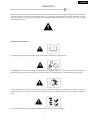
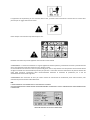
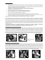
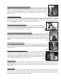
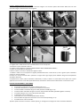
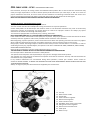
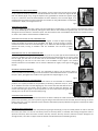
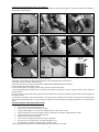
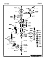
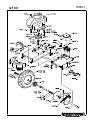
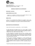
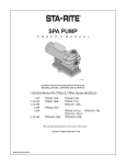
1
CLH CABLE LAYER INTERRAFILO PROFESSIONALE PROFESSIONAL CABLE LAYER MACHINE MODELLO – MODEL NT 60 MANUALE DI USO E MANUTENZIONE ESPLOSO RICAMBI MANUAL FOR USE AND MAINTENANCE SPARE PARTS Via Copernico, 85 47100 Forlì (FC) ‐ITALY‐ ITALIANO IMPORTANTE! Questa macchina è stata costruita secondo le norme CE ed è certificata con il marchio All’interno di questo manuale e sulla macchina sono presenti indicazioni e scritte seguite dal segnale di pericolo sotto riportato che stanno ad indicare un potenziale pericolo. E’ opportuno quindi prestare particolare attenzione a ciò che viene rappresentato o scritto al fine di garantire una maggiore sicurezza all’operatore e a chiunque si trovi nel raggio d’azione della macchina. Segnale di pericolo DESCRIZIONE DEI SIMBOLI E’ opportuno leggere questo manuale d’uso prima di avviare la macchina e iniziare il lavoro. ATTENZIONE!!! Il carburante è altamente infiammabile, maneggiarlo quindi con particolare attenzione e cautela. Non fate mai per nessun motivo rifornimento con il motore in moto, o mentre fumate, o in presenza di fiamme o scintille. La macchina durante il lavoro può lanciare sassi, pezzi di erba o altri oggetti. E’ opportuno che l’operatore, per non arrecare danni a terzi, prima di usare la macchina si accerti che non vi siano altre persone per un raggio di almeno 15 metri. La macchina è dotata di un organo rotante tagliente. Non avvicinare mai mani e piedi!!! 2 E’ opportuno che l’operatore, per non arrecare danni a terzi, prima di usare la macchina si accerti che non vi siano altre persone per un raggio di almeno 15 metri. Usare sempre una maschera di protezione per il viso. Etichetta riassuntiva dei pericoli applicata sulla macchina e ben visibile ATTENZIONE!!! La macchina è dotata di un organo tagliente di estrema potenza, pertanto tenere mani e piedi lontano da esso e non intervenire mai sulla macchina con il motore in moto. Si raccomanda di non lavorare in zone con presenza di ghiaia, sassi e corpi estranei vari che possono essere lanciati dai fili di taglio risultando così estremamente pericolosi per persone o cose nelle vicinanze. Allontanare le persone almeno 30 metri dalla macchina. L’operatore deve necessariamente indossare la maschera di protezione per il viso ed eventualmente anche stivali di gomma. ATTENZIONE!!! Non avvicinare le mani per nessun motivo al meccanismo di oscillazione posto sulla macchina, tale meccanismo può schiacciare le dita delle mani. N.B. L’APPLICAZIONE DI TALI NORME NON E’ UNA PERDITA DI TEMPO! ESSE CONTRIBUISCONO A NON RECARE DANNI IRREPARABILI A PERSONE O COSE E GARANTISCONO UNA SICUREZZA PER L’OPERATORE. TARGA CE IDENTIFICATIVA DELLA MACCHINA. 3 CLH CABLE LAYER – NT 60 INTERRAFILO PROFESSIONALE Gentile Cliente, La ringraziamo per la fiducia accordata a ECOTECH ITALIA e confidiamo che l’uso della nuova macchina risponda pienamente alle Sue esigenze. Al fine di un utilizzo ottimale dell’interrafilo e di una efficace manutenzione nel tempo, La preghiamo di leggere tutte le indicazioni e le avvertenze descritte in questo libretto che dovrà essere conservato e accompagnare sempre la macchina. PRIMA DI AVVIARE LA MACCHINA LEGGERE ATTENTAMENTE LE ISTRUZIONI PER L’USO! NORME GENERALI ANTINFORTUNISTICHE Usare sempre la macchina con estrema cautela. Leggere scrupolosamente questo manuale prima di iniziare il lavoro con la macchina. Sulla macchina si trovano delle etichette di sicurezza: esse non sono figure decorative! Servono a ricordare all’operatore in qualunque momento quali sono i danni che possono essere provocati dall’uso improprio della macchina. Prestare quindi sempre una particolare attenzione a ciò che esse rappresentano. La macchina è dotata di un organo rotante composto da una fresa di acciaio estremamente tagliente. TENERE ASSOLUTAMENTE LONTANO MANI E PIEDI DA TALE ORGANO DI TAGLIO !!! Qualora la macchina venga ceduta in mano ad altre persone, assicurarsi che esse siano a conoscenza delle suddette norme antinfortunistiche e delle istruzioni d’uso. Prima di iniziare il lavoro, assicurarsi che nel terreno non vi siano oggetti che possono essere lanciati dalla macchina diventando estremamente pericolosi per chiunque si trovi nelle vicinanze. Tenere persone, animali o cose ad una distanza di minimo 15 metri dalla macchina. L’operatore, onde evitare di essere colpito da oggetti lanciati, deve obbligatoriamente indossare: MASCHERA DI PROTEZIONE PER IL VISO, TUTA, SCARPONI, GUANTI, BERRETTO. Non eseguire mai la manutenzione della macchina con il motore in moto. ARRESTARE OBBLIGATORIAMENTE IL MOTORE PRIMA DI INTERVENIRE. Non manomettere o disattivare i dispositivi di sicurezza. L’operatore è sempre responsabile dei danni recati a terzi. L’utilizzo improprio della macchina da parte dell’operatore comporta il decadimento della garanzia ed il declino di ogni responsabilità. Se durante il lavoro si nota un malfunzionamento della macchina rivolgersi al centro di assistenza dove l’avete acquistata. NON CERCARE MAI DI RIPARARE LA MACCHINA DA SOLI. L’INESPERIENZA PUO’ PROVOCARE DANNI PEGGIORI. Usare sempre ricambi originali forniti dalla casa costruttrice. 1‐ Tappo del carburante 2‐ Manopola avviamento motore 3‐ Manettino del gas 4‐ Registro dell’innesto fresa 5‐ Registro dell’avanzamento 6‐ Leva innesto fresa 7‐ Leva comando oscillazione manubrio 8‐ Registro del comando oscillazione 9‐ Leva innesto avanzamento 10‐ Raccoglitore del cavo 11‐ Tappo dell’olio motore Fig.1 4 ISTRUZIONI PER L’USO Prima di avviare il motore • Controllare che il livello dell’olio non sia sotto il minimo: svitare il tappo (fig.1 n.11), con uno straccio pulire l’asta di livello e riavvitare il tappo. Svitare nuovamente e assicurarsi che il livello sia compreso fra le due tacche di minimo e di massimo. Se il livello è sotto la soglia minima, aggiungere olio fino a ottenere il livello ottimale. (richiedere l’olio adatto al vostro rivenditore di fiducia). ATTENZIONE!!! LA MACCHINA DA NUOVA VIENE FORNITA SENZA OLIO MOTORE • Assicurarsi che tutte le viti siano ben serrate. • Controllare che tutte le leve siano in posizione di folle (fig.1 n.6/n.9). • Pulire il filtro dell’aria qualora vi siano delle impurità (vedi libretto motore). • Rifornire di carburante la macchina usando un imbuto munito di filtro. • Aprire il rubinetto del carburante (vedi libretto motore). • Per avviare il motore da freddo posizionare il manettino del gas (fig.1 n.3) nella posizione di START. • Impugnare la manopola di avvio del motore (fig.1 n.2) quindi dare uno strappo energico. Attendere qualche minuto che raggiunga la temperatura d’esercizio prima di portarlo al massimo regime. SI RACCOMANDA DI ATTENERSI ANCHE ALLE ISTRUZIONI DESCRITTE NEL LIBRETTO MOTORE. Prima di iniziare il lavoro bisogna posizionare il cavo nell’apposito avvolgitore, regolare la profondità di interramento, legare l’estremità del cavo ad un picchetto, assicurarsi che non vi siano persone animali o cose di valore per un raggio di almeno 15 metri, quindi avviare il motore e una volta caldo portarlo è possibile iniziare il lavoro. Azionare fino in fondo la leva di innesto rotazione della fresa (fig.1 n.9), innestare fino in fondo la leva di avanzamento (fig.1 n.1) e iniziare il lavoro usando comunque la massima prudenza. Leggere attentamente la descrizione delle operazioni sotto riportate. Durante i periodi estivi o comunque in presenza di terreno secco si consiglia di annaffiare abbondantemente il prato il giorno prima di eseguire il lavoro. LA MACCHINA NECESSITA DI UN RODAGGIO! DURANTE LA PRIMA ORA DI LAVORO LE CINGHIE SI ASSESTANO. CONTROLLARE CHE LE MOLLE DI TENSIONE LAVORINO SEMPRE IN MODO ADEGUATO (fig.1 n.4/n.5). POSIZIONAMENTO DEL CAVO NEL RACCOGLITORE Per un utilizzo migliore della macchina data la varietà dei tipi di cavo e dei tipi di bobine esistenti sul mercato si consiglia di avvolgere il cavo nell’apposito raccoglitore (fig.1 n.10) utilizzando la manovella presente sul raccoglitore. È importante avvolgere il cavo in senso orario per garantire durante il lavoro un perfetto srotolamento (fig. 2). Se si vuole invece usare le bobine di cavo già avvolte, si può smontare dal raccoglitore la parete sinistra allentando i tre pomelli (fig.3) e facendo compiere alla parete una leggera rotazione, posizionare la bobina nel tubo del raccoglitore usando eventuali adattatori, quindi rimontare la parete e stringere a fondo i tre pomelli. Una volta posizionato il cavo nel raccoglitore bisogna infilare l’estremità del cavo all’interno del tubo della pinna (fig. 4) fino a farlo uscire dalla parte inferiore di alcuni centimetri. 1‐ Piastra smontabile 2‐ Pomello Fig.2 Fig.3 Fig.4 MONTAGGIO O SOSTITUZIONE DELLA FRESA La macchina è dotata di un meccanismo che permette la rapida sostituzione della fresa senza l’utilizzo di attrezzi (fig.5). Per il montaggio o la sostituzione della fresa bisogna spingere la testina (fig.6) verso l’alto, sfilare la fresa usurata se già presente nella testina (fig.7) e inserire la nuova fresa sempre tenendo la testina premuta verso l’alto, quindi rilasciare la testina che grazie ad una molla va a riposizionasi nella posizione iniziale bloccando automaticamente la fresa. Nel caso di sostituzione della fresa durante il lavoro è necessario pulire bene la testina togliendo i residui di erba e terra e assicurarsi durante il montaggio della nuova fresa che non entrino dei detriti nel meccanismo di innesto rapido. Si consiglia comunque di pulire e ungere frequentemente il suddetto meccanismo (vedi anche “PULIZIA DELLA TESTINA”). Fig.7 Fig.5 Fig.6 5 REGOLAZIONE DELLA PROFONDITA’ DI INTERRAMENTO Per regolare la profondità bisogna agire sul pomello montato nella parte posteriore della pinna (fig.8 n.1). Allentare il pomello di qualche giro in senso antiorario, alzare o abbassare il supporto delle due ruotine posteriori (fig.8 n.3) utilizzando come riferimento per la profondità l’asticella graduata a fianco del supporto (fig.8 n.2) e una volta individuata la profondità voluta stingere a fondo il pomello (fig.8 n.1) in senso orario. I numeri sull’asticella corrispondono a centimetri e venno da 1 a 6. Fig.8 REGOLAZIONE DELLA VELOCITA’ Per regolare la velocità di interramento agire sul manettino dell’acceleratore (fig.1 n.3) andando ad alzare o diminuire i giri del motore. Non regolare MAI la velocità facendo slittare leggermente i dischi frizione della scatola di trasmissione. Questa operazioni crea un grave danno alla parte meccanica della trasmissione. La leva di avanzamento (fig.1 n.9) deve essere tirata SEMPRE fino in fondo e cioè quando va a toccare il manubrio. REGOLAZIONE DELL’ALTEZZA DEL MANUBRIO La macchina permette cinque altezze del manubrio. Per regolare tale altezza allentare in senso antiorario la maniglia posteriore del manubrio (fig.9 n.2) fino a sfilare il pomello (fig.9 n.1), selezionare l’altezza desiderata quindi rinfilare il pomello nel nuovo foro, riavvitare in senso orario e stringere a fondo la maniglia. Fig.9 REGOLAZIONE RAPIDA DELL’INCLINAZIONE DEL MANUBRIO Quando ci si appresta a lavorare sotto a siepi, rami sporgenti, paletti o qualsiasi tipo di ostacolo laterale è possibile inclinare il manubrio dalla parte opposta dell’ostacolo (fig. 10). Per regolare l’inclinazione tirare a fondo la leva posta nella parte inferiore sinistra del manubrio (fig.1 n.7) andando a posizionare il perno corrispondente in uno dei nove fori posti sulla cremagliera alla base del manubrio. La macchina permette dunque quattro livelli di inclinazione a destra e quattro a sinistra. Fig.10 BLOCCAGGIO DELLA PINNA ORIENTABILE Quando ci si appresta ad interrare il cavo per dei tratti rettilinei lunghi, è possibile bloccare la pinna orientabile (fig.11) per garantire una maggiore direzionalità alla macchina. Per bloccare la pinna è sufficiente stringere la maniglia posizionata nella parte laterale destra dell’apparato di supporto (fig.11 n.1). Fig.11 REGOLAZIONE DELLA LARGHEZZA DELLE RUOTE Entrambe le ruote sono dotate di semiassi allargabili in 4 posizioni. Questo sistema offre la possibilità di avere una distanza della fresa rispetto al bordo regolabile che può essere di 25, 27, 29 o 31 cm. (fig.12). Ciò permette di avere un interramento del cavo equidistante da un qualunque bordo, muretto, o siepe. Per regolare questa distanza basta sfilare il perno di bloccaggio (fig.12 n.2) e andarlo a riposizionare in uno dei 4 fori sul semiasse (fig.12 n.1) quindi riboccare la molla di sicurezza. Fig.12 INIZIO DEL LAVORO Una volta posizionato il cavo e montato la fresa, bisogna vincolare il cavo al terreno. Per tale operazione è sufficiente affondare una punta o un picchetto nel terreno e legarvi il pezzo di cavo che fuoriesce dalla parte inferiore della pinna. Questa operazione serve a garantire l’interramento del cavo nel taglio che la fresa va a creare nel terreno durante i primi metri di lavoro. FINE DEL LAVORO Una volta portato a termine il lavoro, per arrestare il motore, portare il manettino del gas (fig.1 n.3) sulla posizione di STOP e (oppure se il motore ne è provvisto utilizzare l’interruttore di stop sempre dopo aver portato il regime di giri al minimo), e nel caso sia presente, chiudere il rubinetto della benzina. Una volta rientrati dal lavoro è indispensabile pulire e ungere la testina della fresa (vedi paragrafo successivo). 6 PULIZIA E MANUTENZIONE DELLA TESTINA Alla fine di ogni utilizzo della macchina è necessario eseguire una accurata pulizia della testina della fresa. Per tale operazione seguire attentamente le fasi seguenti. 1‐ Inclinare la macchina in avanti e appoggiarla a terra con delicatezza. 2‐ Togliere tutti i residui di erba e terra e soffiare bene con aria compressa. 3‐ Smontare la pinna svitando le due viti 4‐ Togliere la fresa (leggere il paragrafo “MONTAGGIO O SOSTITUZIONE DELLA FRESA”). 5‐ Svitare la vite di finecorsa della testina. 6‐ Sfilare la testina, la molla, il distanziale e togliere la sfera. 7‐ Soffiare il tutto con aria compressa e togliere perfettamente tutti i residui di terra, erba e grasso sporco aiutandosi anche con un buon solvente. 8‐ Pulire con un buon solvente tutti i particolari e ungere bene ogni singolo pezzo. Mettere del grasso idrorepellente sull’albero della fresa. 9‐ Riposizionare la sfera, infilare nell’albero il distanziale, la molla, la testina. La molla deve essere posta con la parte appuntita verso il basso e cioè dalla parte della testina. Riavvitare la vite di finecorsa della testina e rimontare la fresa. POSSIBILI INCONVENIENTI E LORO RIMEDI A. Il motore non parte: assicurarsi che • sia presente il carburante nel proprio serbatoio (fig.1 n.1). • il rubinetto della benzina, se presente nel motore, non sia chiuso. • a motore freddo il manettino del gas sia nella posizione di START (fig.1 n.3). • a motore caldo il manettino del gas non si trovi nella posizione di START (potrebbe ingolfare il motore). • il manettino del gas non si trovi nella posizione di STOP. • il carburante arrivi al carburatore. • il filtro dell’aria non sia otturato (vedi libretto motore). • Il foro di sfiato sul tappo del carburante non sia chiuso da impurità (fig.1 n.1). • la candela riesca a dare la scintilla. Qualora questi interventi non diano il risultato sperato, Vi consigliamo di rivolgervi al vostro rivenditore di fiducia. 7 B. C. • • • La fresa, innestata la leva corrispondente, non ruota: verificare che la cinghia non sia usurata. controllare che la cinghia non sia uscita dalle pulegge. assicurarsi che la leva riesca a mettere in adeguata trazione la cinghia. La fresa, disinnestata la leva, continua a ruotare: • verificare che il freno puleggia sia innestato. In caso contrario rimuovere il cofano e allentare il registro fino a quando il ferodo va ad appoggiarsi sulla spalla della puleggia. • controllare che il ferodo non si sia consumato D. La macchina non lavora in modo adeguato: controllare • che la fresa non siano troppo consumata. • che la fresa non sia rotta o non sia stata montata. • che il filtro dell’aria (vedi libretto motore) non sia troppo otturato causando una notevole perdita di potenza del motore. In tal caso soffiarlo con aria compressa o sostituirlo con uno nuovo che potrete acquistare dal Vostro rivenditore di fiducia. • che la benzina non stia per finire. • che il livello dell’olio motore non sia sotto la soglia minima (fig.1 n.11). E. Innestata la leva avanzamento, la macchina non si muove: • Intervenire sul registro del filo di innesto avanzamento nel caso il filo sia troppo lento (fig.1 n.5). • verificare che le cinghie di trasmissione non siano troppo usurate. • verificare che la catena non sia spezzata o troppo lenta. • Verificare che i dischi frizione all’interno della scatola di trasmissione non siano troppo usurati. F. La macchina risulta dura nelle sterzate: • Verificare che la maniglia (fig.11 n.1) sia lenta. G. La testina della fresa non scorre impedendo la sostituzione della fresa stessa: • Pulire l’apparato e rimuovere eventuali residui. (vedi paragrafo “PULIZIA E MANUTENZIONE DELLA TESTINA”). • Assicurarsi che non vi sia formato ossido all’interno del sistema dopo un periodo di non utilizzo. (vedi paragrafo “PULIZIA E MANUTENZIONE DELLA TESTINA”). NON INTERVENIRE MAI SUI REGISTRI DEI FILI SE NON SI CONOSCONO LE FINALITA’! QUESTA OPERAZIONE POTREBBERE COMPROMETTERE IL CORRETTO FUNZIONAMENTO DELLA MACCHINA! MANUTENZIONE DELLA MACCHINA Durante lunghi periodi di inattività della macchina sarebbe opportuno: pulire e lubrificare la testina della fresa (vedi paragrafo “PULIZIA E MANUTENZIONE DELLA TESTINA”), vuotare il serbatoio del carburante (fig.1 n.1), lubrificare il cilindro con prodotti idonei che potrete acquistare dal Vostro rivenditore, Pulire il filtro dell’aria (vedi libretto motore), vuotare la benzina residua dalla vaschetta del carburatore, ungere le parti sverniciate per usura o urti della macchina e le parti dove il trattamento di zincatura risulta consumato onde evitare possibili formazioni di ruggini, soffiare con aria compressa la macchina se dopo il lavoro presenta parti bagnate. E’ assolutamente sconsigliato l’uso di pompe idrogetto. Per qualsiasi intervento sul motore, attenersi alle indicazioni del libretto motore fornito con la macchina. Generalmente è opportuno controllare il livello d’olio almeno ogni 8 ore di lavoro e pulire il filtro dell’aria ogni 4 ore o anche più spesso se si sta lavorando in zone molto polverose. Per un buon uso della macchina non forzare mai il motore; se si nota del fumo bianco fuoriuscire dallo scarico occorre rallentare. DATI TECNICI MOTORE………………......................... HONDA GCV 160 4 tempi a scoppio. POTENZA……………………………………………………………....……………………4,5 kW. AVVIAMENTO……………………...………………….a strappo con autoavvolgente. TRASMISSIONE…………………………………….…………meccanica a bagno d’olio. FRIZIONE…………………….………………………………….…a cinghia con galoppino. VELOCITA’ A MASSIMI GIRI MOTORE…………….…….……………….36 Mt./min. PROFONDITA’ DI INTERRAMENTO…………………………..…….…….da 1 a 6 cm. DISTANZA FRESA DAL BORDO RUOTA…..……………..…..…25, 27, 29, 31 cm. PESO A SECCO………………………………………………………………………..……..49 kg. 8 ENGLISH IMPORTANT! This machine is built in compliance with the EC Directives and is certified with the marking This manual contains indications and messages, followed by the warning symbol below, which can also be found upon the machine itself. These warnings indicate potential hazards. Therefore, in order to ensure maximum operator safety, as well as the safety of anyone within the machine’s field of action, it is recommended to pay close attention to the indications and/or messages contained within these warnings. Danger symbol DESCRIPTION OF THE SYMBOLS This user manual must be read and fully understood before activating and operating the machine. ATTENTION!!! The machine’s fuel is highly flammable and must be handled with extreme caution. Fuel must never be added to the machine’s fuel tank while the motor is running, while smoking, or in the presence of sparks or open flames. The machine may project rocks, pieces of grass or other objects while in function. In order to avoid causing personal injury to any third parties who may be present, the operator must make sure that nobody is within 15 meters of the machine before activating it. This machine is equipped with a sharp rotating element. Keep your hands and feet at a safe distance!!! 9 In order to avoid causing personal injury to any third parties who may be present, the operator must make sure that nobody is within 15 meters of the machine before activating it. Always use a protective visor when operating the machine. This label outlines all of the machine’s potential hazards. It can be found upon the machine in a visible location. ATTENTION!!! The machine is equipped with an extremely powerful cutting element. Always keep your hands and feet at a safe distance from this element and never perform any operations upon the machine while the motor is running. It is recommended to never use the machine in the presence of gravel, small rocks and/or foreign objects. Such elements could be projected by the cutting wires and pose an extreme danger to anyone or anything in the machine’s vicinity. Keep people at least 30 meters away from the machine while it is in function. The operator must wear a protective face shield and rubber boots while operating the machine. ATTENTION!!! The machine’s swing‐action mechanism represents a serious crushing hazard to the fingers. Keep your hands away from it at all costs. Note IT IS EXTREMELY IMPORTANT THAT THESE REGULATIONS BE RESPECTED! THEIR APPLICATION SERVES TO PREVENT SERIOUS PERSONAL INJURY OR PROPERTY DAMAGE, AS WELL AS TO ENSURE AN ADEQUATE LEVEL OF OPERATOR SAFETY. MACHINE IDENTIFICATION PLATE AND CE MARKING 10 CLH CABLE LAYER – NT 60 PROFESSIONAL CABLE LAYER Dear Customer, thank you for having chosen this ECOTECH ITALIA product. We are certain that this machine will fully meet you usage requirements. In order to obtain optimal performance from your cable layer, as well as to ensure its proper maintenance over time, be sure to read all of the indications and warnings contained within this manual. This manual must be preserved and must always remain with the machine for the duration of its working life. READ THE USER INSTRUCTIONS CAREFULLY BEFORE STARTING THE MACHINE! GENERAL ACCIDENT PREVENTION REGULATIONS Always use extreme caution when operating the machine. This user manual must be read carefully before using the machine for any work operations. Various safety labels can be found upon the machine: these are not decorative elements! They serve to continuously remind the operator of the damage and injuries which can result from improper machine use. Always pay special attention to the hazards and warnings indicated by them. This machine is equipped with an extremely sharp, rotating, steel cutter. KEEP YOUR HANDS AND FEET AT A SAFE DISTANCE FROM THIS CUTTING DEVICE!!! If the machine is sold or transferred to a third party for any reason, the party in question must be informed of the above accident prevention regulations and must be provided with the machine’s user instructions. Before beginning any work operations, make sure that the terrain within the operating area does not contain any objects which could be projected by the machine. Such objects could pose a serious hazard to anyone in the vicinity. Keep people, animals and foreign objects at least 15 metres away from the machine while it is in function. In order to avoid being struck by any projected objects, the operator must wear: A PROTECTIVE VISOR, COVERALLS, SAFETY SHOES, GLOVES AND A PROTECTIVE CAP. Never perform maintenance upon the machine while the motor is running. THE MOTOR MUST ALWAYS BE SHUT OFF BEFORE PERFORMING ANY INTERVENTIONS. Do not tamper with or deactivate the machine’s safety devices. The operator shall always bear full responsibility for any injuries or damage caused to third parties. The improper use of the machine on behalf of the operator shall void the machine’s warranty and shall exonerate the manufacturer of any responsibility. If any machine malfunctions are encountered during work operations, contact your reseller’s service centre for assistance. NEVER ATTEMPT TO REPAIR THE MACHINE ON YOUR OWN. INEXPERIENCED REPAIR OPERATIONS CAN LEAD TO MORE SERIOUS DAMAGE. Always use original spare parts which have been supplied by the manufacturer. 12‐ Fuel cap 13‐ Motor starter handle 14‐ Gas throttle 15‐ Cutter activation regulator 16‐ Advancement regulator 17‐ Cutter activation lever 18‐ Handlebar swing‐action control lever 19‐ Swing‐action control regulator 20‐ Advancement activation lever 21‐ Cable spool 22‐ Motor oil cap Fig.1 11 USER INSTRUCTIONS Before starting the motor • Make sure that the oil level is not below minimum: Unscrew the cap (fig.1 no.11), use a rag to clean the dip stick and screw the cap back on. Unscrew the cap again and check whether the oil level falls within the minimum and maximum levels indicated. If the oil level is below minimum, add more oil until a suitable level is reached. (ask a trusted supplier for a suitable oil typology). ATTENTION!!! THE MOTOR OIL DOES NOT COME SUPPLIED WITH THE MACHINE • Make sure that all of the screws are tightened properly. • Make sure that all of the levers are in their neutral positions (fig.1 no.6/no.9). • Clean the air filter of any obstructions (see the motor’s manual). • Refuel the machine through its filtered fuel opening. • Open the fuel tap (see the motor’s manual). • If the motor is cold, the gas throttle (fig.1 no.3) must be set to its START position. • Pull the motor’s starter handle (fig.1 no.2) with force. Before using the machine, wait for a few minutes in order to allow the motor to reach its proper operating temperature. BE SURE TO ALSO FOLLOW THE INSTRUCTIONS DESCRIBED WITHIN THE MOTOR’S MANUAL. Before initiating any work activities, position the cable upon the spool, adjust the machine’s cable laying depth and tie the loose end of the cable to a peg. Make sure that there are no people, animals or foreign objects within 15 metres of the machine. Start the motor and wait for it to reach its proper operating temperature before beginning. Bring the cutter activation lever (fig.1 no.9) and the advancement activation lever (fig.1 no.1) to their working positions and begin working. Use maximum caution while operating the machine. Be sure to carefully read the operation descriptions provided below. During the summer, or whenever operating upon dry terrain, it is recommended to water the operating area abundantly the day before the work is to be performed. THE MACHINE MUST BE SUBJECTED TO A TRAIL STAGE! THE BELTS WILL ADJUST DURING THE FIRST HOUR OF WORK. MAKE SURE THAT THE TENSION ADJUSTMENT SPRINGS ARE ALWAYS WORKING PROPERLY (fig.1 no.4/no.5). POSITIONING THE CABLE UPON THE SPOOL Given the various cable and spool typologies which are available on the market, it is recommended that the cable be wound upon the supplied cable spool (fig.1 no.10), using the appropriate handle upon the spool itself. This will facilitate the cable loading operations. In order to guarantee proper unwinding (fig.2), it is important that the cable be wound upon the spool in a clockwise direction. If the user should want to use a spool with cable already wound upon it, the left hand side of the supplied cable spool can be removed by loosening the three knobs (fig.3) and by slightly turning the side of the spool itself. Position the new spool over the supplied spool’s central cylinder, using any adaptors as required, and reattach the side which was previously removed. Be sure to tighten the fastening knobs properly. Once the cable has been properly positioned upon the spool, the loose end of the cable must be inserted into the appropriate tube (fig.4) until a few centimetres of cable come out the bottom. 1‐ Removable plate 2‐ Knob Fig.2 Fig.3 Fig.4 INSTALLING OR REPLACING THE CUTTER The machine is equipped with a mechanism which allows for the cutter to be quickly replaced without the need for tools (fig.5). In order to install or replace a cutter, push the support (fig.6) upwards and extract the worn cutter, if already present upon the support (fig.7). While keeping the support pressed upwards, insert the new cutter then release the support. A spring action mechanism will automatically reposition the support in its original position, thereby locking the new cutter in place. If replacing a worn cutter during work activities, it may be necessary to clean any residual grass and/or soil off of the support. Make sure that no debris enters the quick attachment mechanism while installing the new cutter. It is nevertheless recommended to clean and lubricate the quick attachment mechanism frequently (see also “CLEANING THE CUTTER SUPPORT”). Fig.7 Fig.6 Fig.5 12 ADJUSTING THE CABLE LAYING DEPTH In order to adjust the machine’s cable laying depth, use the knob on the back of the pin (fig.8, no.1). Loosen the knob by a few turns counter‐clockwise and raise or lower the support for the two rear wheels (fig.8, no.3), using the depth of the graduated bar beside the support (fig.8, no.2) as a reference. Once the desired depth has been obtained, turn the knob (fig.8, no.1) clockwise until it has been properly tightened. The numbers on the graduated bar correspond to centimetres in depth, and range from 1 to 6. Fig.8 ADJUSTING THE SPEED In order to adjust the cable layer’s speed, use the accelerator’s throttle (fig.1, no.3) to increase or decrease the motor’s rpm value. NEVER adjust the speed by making the clutch disks for the transmission’s gearbox slip. This can cause serious damage to the transmission’s mechanical parts. The advancement lever must ALWAYS be pulled to its maximum extent, or rather until it makes contact with the handlebar unit. ADJUSTING THE HEIGHT OF THE HANDLEBAR UNIT The machine provides for five different handlebar heights. In order to adjust the height, loosen the handle at the back of the handlebar unit (fig.9, no.2) by turning it counter‐ clockwise until the knob can be extracted (fig.9, no.1). Select the desired height and then reinsert the knob, turning it clockwise until the handlebar unit has been properly tightened. Fig.9 ADJUSTING THE TILT OF THE HANDLEBAR UNIT When working around hedges, protruding branches, posts or any other type of lateral obstacle, the machine’s handlebar unit can be tilted to the side opposite the obstacle (fig.10). In order to adjust the tilt angle, pull the lever on the lower left of the handlebar unit (fig.1 no.7) and insert the corresponding pin into one of the nine holes in the handlebar unit’s support. The machine therefore allows for the handlebar unit to assume 4 different tilt angles, to the right as well as to Fig.10 the left. BLOCKING THE ADJUSTABLE PIN When laying cable for long straight tracts, the adjustable pin (fig.11) can be locked in place in order to provide for better management of the machine’s advancement direction. In order to lock the pin in place, just tighten the handle on the right side of its support (fig.11, no.1). Fig.11 ADJUSTING THE WIDTH OF THE WHEELBASE Both of the wheels are equipped with half‐axles which can be extended to 4 different positions. This system provides for the possibility of obtaining a distance of 25, 27, 29 or 31 cm between the cutter and the edge (fig.12). This ensures that the cable will be laid at an equal distance from any border, wall or hedge. In order to adjust this distance, just remove the locking pin (fig.12 no.2) and reposition it in one of the 4 holes along the half‐ axle (fig.12 no.1). Be sure to reset the safety spring. Fig.12 STARTING WORK OPERATIONS Once the cable bas been mounted and the cutter has been installed, the cable must be tied to the ground. In order to perform this operation, just insert a spike or peg into the ground and tie the end of the cable, which is sticking out of the bottom of the pin, to it. This operation ensures that the cable will be properly laid within the groove created by the cutter for the first few meters. FINISHING WORK OPERATIONS Once the work operations have been completed, bring the gas throttle (fig.1 no.3) to its STOP position in order to shut off the motor (the motor can also be shut off by means of the stop switch, if installed, after having brought the motor’s speed to minimum). Once the motor has been shut off, close the fuel tap. Once the machine has been brought to its storage location, the cutter’s support must be cleaned and lubricated (see the following section). 13 CLEANING AND MAINTAINING THE CUTTER SUPPORT When finished using the machine, the cutter support must be cleaned thoroughly. In order to perform this operation, follow the procedure below. 1‐ Tip the machine forward and rest it gently on the floor. 2‐ Remove any residual grass and soil and clean the unit thoroughly with compressed air. 3‐ Remove the two screws to detach the pin 4‐ Remove the cutter (see the section entitled “INSTALLING OR REPLACING THE CUTTER”). 5‐ Unscrew the support’s stopper screw. 6‐ Extract the support, the spring and the spacer and then remove the sphere. 7‐ Clean everything with compressed air, removing any residual soil and grass, and use a good solvent to clean away any greasy residues. 8‐ Clean all of the components with a good solvent and lubricate each piece thoroughly. Apply water‐repellent grease to the cutter’s shaft. 9‐ Reposition the sphere and insert the spacer, the spring and the support into the shaft. The spring must be positioned with its loose end downwards, or rather facing the support. Screw the support’s stopper screw back in and reinstall the cutter. POSSIBLE SETBACKS AND RELATIVE SOLUTIONS A. The motor does not start: make sure that • there is fuel in the fuel tank (fig.1 no.1). • the fuel tap, if present on the motor, is open. • the gas throttle (fig.1 no.3) is set to its START position, if the motor is cold. • the gas throttle is not set to its START position, if the motor is hot (this could flood the motor). • the gas throttle is not set to its STOP position. • the fuel arrives at the carburettor. • the air filter is not obstructed (see the motor’s manual). • the vent hole on the fuel tap is not obstructed (fig.1 no.1). • the sparkplug is capable of providing the necessary spark. If these inspections should not resolve the problem, please contact your reseller. 14 H. • • • The cutter, with its relative activation lever properly engaged, does not turn: check whether the belt is worn. check whether the belt has come off the pulleys. make sure that the lever is able to provide the belt with adequate traction. I. The cutter, with its relative activation lever disengaged, continues to turn: • check whether the pulley brake is engaged. If this is not the case, remove the cover and loosen the adjustment until the brake lining makes contact with the edge of the pulley. • check whether the brake lining has been consumed. J. The machine does not perform properly: check • whether the cutter is excessively worn. • that the cutter is installed and that it is not broken. • whether the air filter (see the motor’s manual) is obstructed, resulting in a significant decrease in motor power. If this is the case, clean it with compressed air or replace it with a new air filter supplied by your trusted reseller. • whether the fuel tank is almost empty. • whether the motor oil level is below its minimum level (fig.1 no.11). K. With the advancement lever properly engaged, the machine does not move: • if the advancement mechanism’s wire is too loose, adjust it using the appropriate regulator (fig.1 no.5). • check whether the transmission belts are excessively worn. • check whether the chain is broken or too loose. • check whether the clutch disks inside the gearbox are excessively worn. L. The machine is abnormally difficult to steer: • check whether the handle (fig.11 no.1) is loose. M. The cutter’s support does not slide, thereby impeding the replacement of the cutter itself: • Clean the mechanism and remove any residues present. (See the section entitled “CLEANING AND MAINTAINING THE CUTTER SUPPORT”). • Make sure that no rust has formed within the system after a certain period of use. (See the section entitled “CLEANING AND MAINTAINING THE CUTTER SUPPORT”). NEVER MAKE ANY ADJUSTMENTS TO THE WIRE REGULATORS IF YOU DO NOT KNOW THEIR PURPOSE! SUCH OPERATIONS COULD COMPROMISE THE MACHINE’S PROPER FUNCTION! MACHINE MAINTENANCE During long periods of machine downtime it is a good idea to: clean and lubricate the cutter support (see the section entitled “CLEANING AND MAINTAINING THE CUTTER SUPPORT”); empty the fuel tank (fig.1 no.1); lubricate the cylinder with an appropriate lubricant supplied by your reseller; clean the air filter (see the motor’s manual); empty the carburettor bowl of any residual fuel; lubricate any of the machine’s painted parts which have been scratched or dented, as well as any of its galvanised parts, in order to prevent the formation of rust; dry any wet portions of the machine. The use of a pressure washer is absolutely not recommended. For any maintenance operations to be performed upon the motor, please follow the indications provided in the motor’s manual, which comes supplied with the machine. It is generally a good idea to check the level of the motor oil after every 8 hours of use and to clean the air filter after every 4 hours of use. These operations should be performed more frequently if working in extremely dusty environments. Never force the machine’s motor; if white smoke comes out of the exhaust, slow down. SPECIFICATIONS MOTOR………………………………………..…………….HONDA GCV 160 4 stroke. MAX POWER……………………………………………………....……………………4,5 kW. STARTING…………………………………...............……………….self‐winding pull. TRASMISSION…………………………………….…….…………………..……….with belt. CLUTCH…………………….…………………………………….……..multidisch with oil. MAX SPEED…………….…….………………………………………….……….36 Mt./min. CABLE LAYING DEPTH……………..…………………………..…….…….da 1 a 6 cm. WIDTH OF THE WHEELBASE …………….……………..…..…25, 27, 29, 31 cm. DRY WEIGHT………………………………………………………………………..……..49 kg. 15 DICHIARAZIONE DI CONFORMITA' CONFORMITY DECLARATION ECOTECH ITALIA via Copernico, 85 47100 Forlì FC - ITALIA, dichiara sotto la sua esclusiva responsabilità che il prodotto: ECOTECH ITALIA via Copernico, 85 47100 Forlì FC - ITALIA, under its own responsibility, declares that the: Interrafilo – Cable layer machine NT 60 Tipo: Type: Numero di serie: Serial number: Peso: Weight: NT 60 (CL) 00001 - 01000 Potenza Max: Max Power: 4,5kw 49 kg Rumorosità Max: Max Noise: 92 dB/A È conforme alle disposizioni della Direttiva Macchine (Direttiva 98/37/CE e Direttiva 2006/42/CE) e alle disposizioni nazionali di attuazione. Is in accordance with the European regulation (98/37 EC and 2000/14/EC), plus subsequent modifications, and with the relevant national provisions. È anche conforme alle disposizioni della Direttiva europea 2000/14/ CE. It also comply with the European regulation 2006/42/EC. Nell'utilizzo devono essere rispettate tutte le istruzioni riportate nel manuale d’uso a corredo dello strumento, nonché tutte le norme in materia di sicurezza e prevenzione degli infortuni vigenti nel paese di utilizzo; sul prodotto è stata apposta la marchiatura CE. While using the machine all instruction, as per the owner manual delivered together with the machine, must be followed as far as all the safety regulation in force in the country; the machine bears the CE mark. Data-Date: Firma-Signature: 20/01/10 16 60400 NT 60 T8020D 2159 6012 11067 2382B 6008 6015 7428 T5016 8109 2417/05 T6060 7440 3517 2343 T6060 2343 7457 2345 T8020 2206 T8040 2343 T6016 T8050 7483 7458 2243 7479 7050 7202 2382B 7456 T8100 2345 2345 2154 2120 3020 6019 10029 7473 2185 7407 2345 7216 2035 3015 6048 2035 7482 7480 2225 2425/10 7481 7406 7443 B5012 7403 17 T8035 60401 NT 60 M01/M02 2345 2345 2206 T8035 x3 T8060 (B&S) T8035 (HONDA) 4002 G6010 7484 G6010 6110 2207 x3 2245 T1105 7472 6121 6122 4052 G6014 10030 4001 2345 2345 7485 T8035 TF6014 7413 8010 7489 T8020 7490 7465 7414 2382B 2204 T6035 TF6014 7417 7490 2345 10160 DX 10161 SX 3125 2118 2418/10 10115 10115 T8018 7487 8048 7467 DX 7468 SX 2418/10 2118 2118 2418/10 5018 7239 7488 10015 18 7466 60402 NT 60 T6020 2254 6043 7491 7476 7459 6045 2383B 7490 7495 6055 8029 7494 7496 7478 T6020 7477 7493 6045 6055 10065 7227 6043 2254 T6020 2383B 7498 2204 T6040 10130 7492 7497 7463 7425 TB8020 10062 7427 7471 7499 2343 7494 T8050 2225 7501 7427 7415 TF6014 T5016 7501 12044 2225 T8050 7452 13198 12098 7469 T8020 19 12044