1
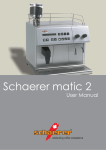
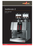
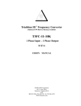
Figure Machine
9208 Venture Ct – C9
Manassas Park VA 20111
[email protected]
www.FigureMachine.com
Installation Manual
TCFLOW-STACK
TCFLOW-STACK EXPLODED VIEW
ABCDEFGHI-
BREATHER SPACER (2)
GASKET (STOCK COMPONENT)
BACK PLATE (1)
KEYWAY COVER (2)
BREATHER BOLT (2)
BOLT; ¼-20 x ½” SOCKET HEAD LOW (3)
O-RING (1)
COLLAR AND VELOCITY STACK (1)
BOLT; ¼-20 X 7/16” SOCKET HEAD (3)
2
Dear Customer,
Thank you for purchasing Figure’s TCFLOW-STACK Air
Cleaner Assembly. This Air Cleaner has been engineered to
enhance the performance and appearance of your bike for
its entire life. Proper installation is essential to your
overall satisfaction, so please read these instructions
before attempting to install. Exercise patience; these
instructions are intended to assist even the most
mechanically challenged.
Remember, if you are not 100% satisfied with our product,
simply return it within 30 days of purchase for a complete
refund.
We always love to see installed pictures, so we encourage
you to email us your best!
(Send to [email protected])
Package Contents (see illustration):
ACDEFGHI*-
BREATHER SPACER (2)
BACK PLATE (1)
KEYWAY COVER (2)
BREATHER BOLT (2)
BOLT; ¼-20 x ½” SOCKET HEAD LOW (3)
O-RING (1)
COLLAR AND VELOCITY STACK (1)
BOLT; ¼-20 x 7/16” SOCKET HEAD (3)
Loctite® RETAINING COMPOUND (.02 oz)
3
TCFLOW-STACK Installation
1) Remove Stock Filter Assembly
1.1) Remove the Allen Cap screw that secures
the Filter Cover.
1.2) Remove the three bolts that secure the stock
filter. Then remove the filter and breather
hoses.
4
1.3) Remove the stock breather bolts and throttle
body bolts. Remove the stock breather box.
Carefully remove the stock air filter gasket
and set aside for later use.
1.4) Some models (Non U.S.) are equipped with
an intake valve solenoid. If so equipped,
unhook the connector on the back of the
stock air cleaner. The connector of this
solenoid will need to be attached to the new
filter backing plate and a bypass module (not
supplied) will need to be installed to prevent
a check engine light.
1.5) Some models are equipped with a carbon
canister vent line. If so equipped, this hose
can be routed to under the bike.
5
2) INSTALL TCFLOW FILTER ASSEMBLY
2.1) Insert three ¼”-20 x ½” LOW head bolts
through the backing plate and then through
the stock gasket (use Loctite on the bolts).
Loosely install the bolts to the intake but do
not fully tighten.
2.2) Insert the breather bolts through key hole, the
backing plate, and finally through the breather
spacers (per the following illustration) and
then finger tighten to the engine (use Loctite
on the breather bolts). IMPORTANT: The
end of the spacer with relief goes against
the backing plate.
6
2.3) After all bolts from steps 2.1 and 2.2 have
been loosely attached, fully tighten the 3
intake bolts and then fully tighten the breather
bolts.
7
2.4) Place the O-ring in the intake groove of the
backing plate. Loosely install the ¼”-20 x
7/16” bolts through the collar and into the
backing plate (use Loctite on the bolts).
2.5) Gradually tighten each bolt such that the collar
is evenly drawn against the backing plate until
all bolts are fully tight and the collar is flat
against the backing plate.
2.6) Stand back and enjoy! Please send any
pictures and/or feedback to:
[email protected]
8