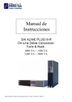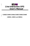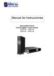
1
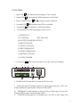
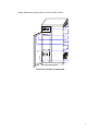
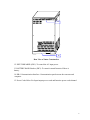
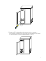
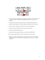
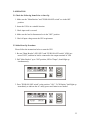
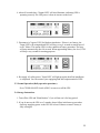
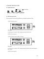
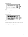
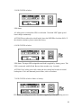
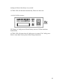
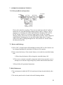
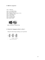
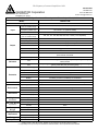
Triathlon III
TM
Uninterruptible Power Supply
(UPS)
(Optional Frequency Converter w/ Battery Backup Available)
T3UPS-11-8K
1 Phase Input – 1 Phase Output
8 KVA
USER'S MANUAL
GEORATOR Corporation
9617 Center Street Manassas, Virginia 20110
USA
800-523-9938, +1 703-368-2101, fax +1 703-368-1078
WWW.Georator.com
1
CONTENTS
Section
Title
Page
1
INTRODUCTION
3
2
FUNCTIONS
4
3
LOCATION OF THE UPS
7
4
CABLE CONNECTION
8
5
OPERATION
11
6
TROUBLE SHOOTING GUIDE
13
7
OPERATION MODES OF THE UPS
18
8
COMPUTER INTERFACE
18
9
SPECIFICATION
22
1. INTRODUCTION
1.1 General Description
The continuity of electrical power with the exact frequency is an essential requirement
for critical load operations. This UPS is a solid state (electronic) type, designed to
meet the needs of computer and other sensitive equipment. The unit is inherently
quiet, and thus well suited for applications where noise is a concern.
1.2 Features
1. Compact size, light weight, easy to transport and place.
2. Special airflow design to avoid dust accumulation.
3. Front door installation, repairing, and user-friendly design.
4. No environmental pollution.
1.3 Important Notices
To be sure that the UPS is operated correctly, the following items should be checked:
1. Read these instructions carefully before operating the UPS.
2. UPS power connection instructions should be followed.
3. Do not open the case while the unit is being operated.
4. If the UPS is stored for long period, the battery (if installed) must be charged every
90 days.
5. Maintain the load within the rating of the UPS to prevent faults.
6. Handle unusual events according to the trouble-shooting guide.
7. Keep the UPS clean and dry.
3
2. FUNCTIONS
1. Input LED
: This indicates the incoming AC line is normal.
2. Output LED
: This means the UPS output power is to the load.
: Battery charge is almost exhausted.
3. Battery Capacity LED
4. Overload LED
: This indicates the UPS is overloaded.
: This indicates a UPS fault condition.
5.
Fault LED
6.
LCD Display: The following displays can be viewed:
(1) UPS STATUS
AC: LOSS (OK)
BAT. OK (LOW)
NO OUTPUT (INVERTER OUTPUT)
(2) INPUT VOLTAGE
(3) OUTPUT VOLTAGE
(4) INPUT FREQUENCY
(5) OUTPUT FREQUENCY
(6) BATTERY VOLTAGE
(7) OUTPUT POWER
: This switch is pressed to select the various LCD displays.
7. LCD Switch
1
2
3
4
5
8. PUSH ON-OFF Switch (SW4): To turn the UPS on or off.
9. VOLTAGE ADJUST Trimmer (option): To adjust output voltage by +-20%. If no
voltage adjustment required, there is no need of this switch.
10. FREQUENCY Switch (option): To choose 50 Hz or 60 Hz output. In case of fix
frequency 400 Hz, there is no need of this switch.
11. VOLTAGE Switch (option): LCD display choice for 120V or 220V output. If no
4
voltage adjustment required, there is no need of this switch.
8
9
10
11
12
13
Front View of Outer Construction
5
14
15
Rear View of Outer Construction
12. INPUT BREAKER (SW1): To control the AC input power.
13. BATTERY BANK Breaker (SW3): To control external batteries If there is
battery.
14. DB-9 Communication Interface: Communication port between the converter and
computer.
15. Power Cords Holes: For Input/output power cords and batteries power cords channel.
6
3. LOCATION OF THE UPS
3.1 Transporting
1. Disconnect all power cables if necessary.
2. Be careful not to damage the UPS while transporting.
3. Don't transport the UPS upside down.
3.2 Positioning
1. Do not put the UPS on uneven or inclined surface.
2. Allow a minimum distance of 4 inches in the rear and two sides of the UPS for
ventilation.
3. Do not expose the UPS to direct sunlight or rain.
4. Keep the UPS far away from heat emitting sources.
5. Do not leave objects on the top of the UPS.
6. Do not expose the UPS to corrosive gas.
7. Maintain the ambient temperature at 0-40oC
7
4. CABLE CONNECTION
4.1 Inspection
1. The system should be installed and wired only by qualified electricians in accordance
with applicable safety regulations.
2. When installing the electrical wiring, please note the nominal amperage of your
incoming feeder.
3. Inspect the packaging carton and its contents for damage. Please inform the transport
agency immediately should you find signs of damage. Please keep the packaging in a
safe place for future use.
4. Please ensure that the incoming feeder is isolated and secured to prevent it from being
switched back on again.
4.2 Caution
1. Do not use household outlet (only 15-20A), because the outlet hasn't sufficient
capacity to support the UPS.
2. Please connect the power of nearest circuit breaker panel to the Converter input
terminal block.
4.3 Cable Connection
1. First, detach 4 screws on the cover panel with a screwdriver to find the terminal
block.
2. The hole to insert input/output power cords is on below of the front panel. Please
connect power cords from the hole.
8
3. Because the UPS is always made to order, once power cords are connected,
please make sure all connectors are correct as per each label instruction stuck beneath
the terminal block and all screws are tightened properly. (Fig 13)
9
Fig 13
4. Please follow load current design for output power cord and use rated power cables to
connect the LINE(L), NEUTRAL(N) and GROUND(G) lines to the connector
terminals.
5. Once the power cords are fixed, please check to confirm that the conductors are
unable to contact with the case or other conductive material to avoid short circuit.
6. Please turn off AC supply to prevent short circuit while connecting lines.
7. Ensure the connected load doesn't exceed the capacity of the UPS.
8. Please provide good grounding system.
9. Please use the nearest point of earth bar or switch box for GROUND line.
10. Please follow applicable NEC provisions, and state/local electrical codes.
11. Improper use of the grounding plug can result in a risk of electric shock. Consult a
qualified electrician or serviceman if the grounding instructions are not completely
understood.
10
5. OPERATION
5.1 Check the Following Items Prior to Start Up
1. Make sure the "Main Breaker" and "PUSH ON-OFF switch" are in the OFF
position.
2. Insure the UPS is in a suitable location.
3. Check input cord is secured.
4. Make sure the load is disconnected or in the "OFF" position.
5. Check if input voltage meets the UPS requirement.
5.2 Initial Start Up Procedure
Please follow the instructions below to start the UPS.
1. Be sure "Main Breaker" (SWI, SW3) and "PUSH ON-OFF switch" (SW4) are
turned "OFF", and that no load is connected to the output terminals of UPS.
2. Pull "Main Breaker" up to "ON" position; LED of "Input", should light up
simultaneously.
3. Press "PUSH ON-OFF switch" to the position " ON ", "LCD Display" shall light up
immediately to indicate the AC utility power and batteries are normal.
11
4. About 20 seconds later, "Output LED" will also illuminate, indicating UPS is
operating correctly The UPS power is from its inverter to the load.
5. Disconnect AC input of UPS for blackout simulation. If there is an battery, the
"Input LED" will extinguish and UPS will beep every 4 seconds to remind user of
an AC failure. This means UPS is in the condition of battery operation. The beep
will stop automatically after 90 seconds. When approaching battery low level, UPS
will beep every second for warning purposes.
6. Re-supply AC utility power, "Input LED" will light up again, then first installation
is completed. You can connect your equipping load into output terminal of UPS.
5.3 Normal Operation (Daily operation procedure)
Press "PUSH ON-OFF Switch (SW4)" to turn on or off the UPS.
5.4 Storage Instructions
1. Turn off the UPS and "Main Breaker" if you will not use it for long period.
2. If you do not use the UPS over 3 months, please follow initial start up procedure
and keep supplying power to the UPS for at least 24 hours to ensure battery is
fully recharged.
12
6. TROUBLE SHOOTING GUIDE
6.1 Symbol References
LIGHTS UP
EXTINGUISH
BUZZER
BUZZER
BUZZER
BUZZER
SOUNDS
SOUNDS
SOUNDS
NO SOUND
CONTINUOUSLY
EVERY 4 SECONDS
EVERY SECOND
6.2 UPS Status and Action
The description of the following guideline may be helpful in problem solving.
1. LED STATUS as below:
UPS Status:
AC utility power is normal; UPS is running normally with full load.
ACTION: None required
2. LED STATUS as below if there is battery:
UPS Status:
AC utility power is normal; UPS is running normally. Batteries have been charged to
90% or more.
ACTION: None required
13
3. LED STATUS as below:
UPS Status:
AC utility power is 220V; UPS is running normally.
ACTION: None required
4. LED STATUS as below:
UPS Status:
AC utility power is normal. UPS is running normally, but battery capacity is low
after several hours charging.
ACTION: Charger has failed. Please replace charger board.
14
5. LED STATUS as below:
UPS Status:
AC utility power is normal but UPS is overloaded. "Overload LED" lights up and
buzzer beeps continuously.
ACTION: Please reduce the critical load to lower the POWER to less than 100%. If
the situation continues, please contact the factory.
6. LED STATUS as below:
UPS Status: The input LED extinguishes and load is supplied by battery power. The
UPS is connected with full load. Buzzer alarm sounds every 4 seconds.
ACTION: If AC utility power fails, reduce the less critical load in order to extend
backup time. If it is not abnormal power failure, refer to flowchart.
7. LED STATUS as below if there is battery:
UPS Status: AC utility power fails. The load is supplied by UPS, and battery power is
15
running out. Buzzer alarm beeps every second.
ACTION: UPS will shut down automatically. Please save data soon.
8. LED STATUS as below:
UPS Status: AC utility power fails and battery runs out. UPS has shut down
automatically.
ACTION: UPS will restart when AC utility power is restored. If AC utility power
failure is more than 6 hours, please follow storage instructions.
16
Trouble Shooting Guide
17
7. OPERATION MODES OF THE UPS
7.1 UPS System Block and Operation
Please refer to the above topology. There are two main loops when AC utility is
normal: the AC loop and the battery charging loop (if there is battery). The AC
output power comes from AG utility input and passes through AC/DC rectifier,
DC/DC booster, and DC/AC inverter to supply power to load. The battery
charging voltage comes from AC utility input and converted by AC/DC charger to
support battery-charging power. In case of AC utility failure, the AC output
comes from battery, passing through DC/DC UPS, and DC/AC inverter within
the battery backup time.
7.2. Battery and Recharge
1. UPS is "ON", or Input breaker SWI and Battery breaker SW3 are ON, batteries can
be recharged automatically, and about 8-10 hours to 90% capacity.
2. Please contact the factory, if the external battery set is needed to extend the backup
time.
1) Please keep the batteries fully recharged to extend the battery life.
2) There are no customer serviceable components inside, do not open the cover or
attempt to serve the unit. High voltage may remain when the unit shuts down.
3) Please follow all operational instructions.
7.3 Daily Maintenance
1. The environment in which the UPS is located must be kept dry and relatively dust
free.
2. The exterior panels can be cleaned with a mild cleaning solution.
18
3. All power connections at the input, battery, output terminals and circuit breaker
must be periodically checked every month.
4. The battery cells used are the sealed maintenance-free type. The factory adjusts
both charging voltage and current according to the battery specifications.
5. If the external battery is the vented lead-acid type, the electrolyte should be
inspected every three months. If liquid level is below the low limit, pure water
must be added to the battery cells.
19
8. COMPUTER INTERFACE
The communication interface (DB9 port) on the back of the UPS may be connected to
a host computer. The port provides two different modes for communicating with the
computer.
Mode 1: Supply RUPS monitoring and management software.
Mode 2: Supply UPSilon2000 monitoring and management software.
8.1 DB9 PIN Assignment
Change to Mode I or Mode 2 of Method
Mode 1: Supply RUPS Monitoring And Management software.
The port simulates relays closing to communicate with the computer. Its major
functions are as follows:
1) To broadcast a warning when power fails.
2) To close any open files before the battery exhausted out.
3) To turn off the UPS.
Mode 2: Supply UPSilon2000 Monitoring And Management software.
The UPS communicates with the computer by sending out RS-232 data streams to
one of the serial ports. By this method the user is able to monitor the following
parameters:
Indicates the present input voltage to the
Input Voltage UPS system when AC power is present.
Indicates the present output voltage of the
Output Voltage UPS.
Indicates the actual output frequency of the
AC Frequency UPS.
Indicates the actual DC voltage of the
Battery Voltage UPS battery.
Indicates the actual temperature inside the
Temperature
UPS.
20
8.2 DB9 Pin Assignments:
PIN 1: UPS Fault
PIN 2: AC POWER Failure
PIN 3: Inverter Power ON
PIN 4: Common Ground of Pin 1,2,3,5,8
PIN 5: UPS Battery Low
PIN 6: Turn off UPS
PIN 7: Ground of Pin 6
PIN 8: inverter Output
PIN 9: RS232 TXD
DB9 INTERFACE CONNECTOR
8.3 Method for Changing into Mode I or Mode 2
Change JP1 Short-Jump according to your requirement.
21
The Frequency Converter People Since 1950
800 523-9938
703 368-2101
GEORATOR Corporation
Fax: 703 368-1078
9617 Center Street
Manassas, VA 20110
E-Mail: [email protected]
Triathlon III UPS Specifications - 1 Phase Input to 1 Phase Output Model, 8 KVA
Model
Capacity
T3UPS-11-8K
8 KVA
Voltage
1 Phase 100, 110, 115, 120, 200, 208, 220, 230, or 240V ± 20%
(select one individual voltage)
Input
Frequency (select one)
50 or 60 Hz ± 5% (Optional 400Hz)
Power Walk In
0-100% < 20 seconds
Voltage
100, 110, 115, 120, 200, 208, 220, 230, or 240V ( ± 5% adjustable)
(select one individual voltage)
Output
Indicators
Protection
Interface
Voltage Regulation
± 1% at Linear Load
Frequency (select one)
50 or 60Hz ± 0.1Hz (Optional 400Hz)
Phase
1 Phase, 2W+G (Optional 3W)
Power Factor
0.7-1 lag
Distortion (THD)
< 3% @ 100% Linear Load
Crest Factor
3:1
Overload Capacity
110% continuous, 110-150% 30 sec., > 150% causes auto-shutdown. Auto restart
upon removal of overload.
Efficiency
> 85%
LCD
UPS Status, I/P&O/P Voltage, I/P&O/P Frequency, Battery Voltage, Loading %,
History Record
LED
Utility LED (green), Inverter LED (green), Battery Low (yellow), Bypass Voltage
(yellow), Fault LED (red), Overload (yellow)
Over/Under Voltage
Alarm
Output Short Circuit
Current Limited and cut-off, fuse and breaker
Overload
150% delay 30 Seconds, then transfer to Bypass & Auto Re-Transfer
Over Temperature
Auto-shutdown
Battery
Low Battery Shutdown and Battery Circuit Breaker
EMI/EMC
EN50091-2, CE Approved
Contact Closure, RS-232
Support MEGATEC RUPS, MEGATEC RUPSII / UPSilon 2000 UPS monitoring software
Operating Temperature
0° – 40° C
Humidity
0 - 90% Non-condensing
Audible Noise
< 45 dB at 1 meter
W x H x D (mm)
480*845*340
W x H x D (in)
18.9*33.3*13.4
Weight *
Kilograms
158.0
w/o batteries
Pounds
348.3
Batt. Cab. Weight
Environment
Dimensions
Kilograms
115.0
w/o batteries
Pounds
253.5
Battery
Weight
Battery Cabinet
Dimensions
Kilograms
124.8
Pounds
275.1
W x H x D (mm)
340*480*845
Battery
Backup Time **
W x H x D (in)
13.4*18.9*33.3
Type - Quantity
7AH - 48 ea.
Minutes - Minimum
16.5 min.
* Weights based on 220V IN and OUT. Weights may vary based on input/output frequency/voltage
** Longer backup times (to 8 hours) are available from standard models; custom specifications also available.