1
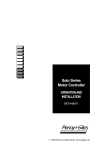
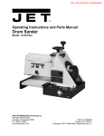
I
nstallation manual from P&G
8.1 Installation manual from P&G (Penny & Giles)
8.1.1.1 Pilot + Operation
Study Chapter 1: Operation. It is important that the information in Chapter 1 is supplied
with the wheelchair, either as part of the wheelchair user handbook or as a separate
document.
This chapter sets out the installation conditions that must be complied with in order to
meet the safety requirements of TÜV Product Service (Germany), ISO7176-14 and
prEN12184.
If a wheelchair manufacturer’s label is placed over the Pilot+ identification label, then to
maintain the control system’s TÜV approval Penny & Giles must be informed. Penny &
Giles will then inform TÜV Product Service.
8.1.1.2 Program Settings
All programmable values are stored within the Power Module, therefore, if you change a
Joystick Module or ALM there is no need to re-program the system. You must supply the
Power Module programmed with the manufacturer’s preset settings. Power Modules are
always supplied by Penny & Giles with the preset settings shown on the relevant data
sheet.
The preset settings are chosen with the wheelchair manufacturer to ensure safe operation
and compliance with relevant legal requirements over the whole of the operating range of
the joystick and speed control.
The wheelchair must stop within the maximum distance specified for the country in
which the wheelchair will be used. TÜV Product Service (Germany) specify the distance
to be as stated in prEN12184.
Users with particular disabilities may need very low braking rates. However, if the control
system is programmed with a low braking rate, the stopping distance may be more than
that specified. If this happens, the maximum speed must be re-programmed so that the
stopping distance requirement is satisfied.
State in the wheelchair user handbook that it is the responsibility of the person
programming the control system to make sure that the stopping distance requirement is
satisfied. If the braking rate is low, the forward and reverse maximum speed settings may
need to be re-programmed.
To assist the person in this task, include a graph in the wheelchair user handbook showing
the relationship between the maximum forward/reverse speed settings and the forward/
reverse braking rate which is required to ensure the correct stopping distance.
It may be possible to program settings which compromise the stability of the wheelchair.
Perform suitable tests to establish which programming restrictions are needed to prevent
instability. State any programming restrictions in the wheelchair user handbook.
State in the wheelchair user handbook that it is the responsibility of the person
programming the control system to make sure that the settings are safe and to note any
programming changes that they make.
52
It is possible for wheelchair manufacturers to limit the values of speeds and accelerations
that can be programmed in the field. This facility ensures a safe-operating envelope for the
wheelchair can be maintained. These limits are set in the factory by Penny & Giles and can
only be altered by Penny & Giles.
WARNING: Programming should only be conducted by healthcare professionals with indepth knowledge of Penny & Giles electronic control systems. Incorrect programming could
result in an unsafe set-up of a wheelchair for the user. Penny & Giles accept no liability for
losses of any kind if the programming of the control system is altered from factory preset
values. Penny & Giles accept no liability for losses of any kind if the drive or stability
characteristics of the wheelchair are altered without prior notification and discussion with
Penny & Giles.
8.1.1.3 Soft-Stop
If the version of Pilot+ you have has the Soft-Stop function enabled (see data sheet), you
must ensure that the emergency stopping distance is within the distance specified for the
country in which the wheelchair will be used. TÜV Product Service (Germany) specify the
distance to be as stated in prEN12184.
8..1.1.4 Other Information
You must provide a diagram in the wheelchair user handbook showing the user controls.
In addition, you should include a brief specification of operating supply voltage range and
operating temperature range.
8.1.2.0 Immobilizing the Wheelchair
8.1.2.1 Prevention of Unauthorized Use
TÜV Product Service requires that the wheelchair must have a means of preventing
unauthorized use. This function is provided in the Pilot+ Joystick Modules, see chapter 1
section 3.2.
8.1.2.2 Charger Interlock
ISO 7176-14 requires you to provide a means of preventing the use of the wheelchair while
the batteries are being charged. The charger sockets fitted to the Pilot+ Joystick Modules
include an inhibit facility, refer to section 5.1 for further details.
Contact Penny & Giles if you need advice.
8.1.2.3 Sleep Mode
The control system can be programmed to “go to sleep” if the joystick is not operated for a
period of time, see chapter 3 section 4.8. The sleep state is indicated a by short blink of the
TruCharge display once every 2.5 seconds.
To re-start, switch the control system off and on again.
53
8.1.3.0 Power Module Wiring
8.1.3.1 General
Study the data sheet for the Power Module to identify the output current, ratings and
restrictions
Recommendations for the cross-sectional area, ratings and materials for wiring are given in
the table in section 3.2. These depend on the application. You are responsible for
establishing the suitability of the particular wiring arrangement used on the wheelchair.
Penny & Giles can make general recommendations for wiring to Pilot+ control systems, but
Penny & Giles accepts no responsibility for the wiring arrangement used.
Make sure that the connectors you use are reliable under all operating conditions and
correctly wired with no short circuits. Do not use unsuitable components - it may result in
poor wheelchair reliability.
The power connectors for the Pilot+ Power Module are specially designed by Penny &
Giles for wheelchair applications. The crimps are standard AMP Timer parts but the
plastic housings are custom. Kits of connectors including the crimps, housings and rubber
boots can be purchased from Penny & Giles or directly from the manufacturers, Intech.
Intech will also provide a pre-assembled cable service. Intech’s details are as below.
Intech
Tel:
+44 (0)1522 575535
Fax: +44 (0)1522 523744
The connector part numbers are:
Connector
Battery
Motor/Brake
P&G Reference
D 49712 PG -80B
D 49713 PG -80M
Intech Part No.
IPG -5202
IPG -5401
Hand tools for crimping and extraction are available from Intech, the references are as
below.
Crimp tool for 0.5-1.0mm2 wire:
Crimp tool for 2.5-4.0mm2 wire:
Crimp tool for 4.0-6.0mm2 wire:
ICT-249
ICT-531
ICT-532
Extraction tool for 0.5-1.0mm2:
Extraction tool for 2.5-6.0mm2:
IET-503
IET-552
For details of automatic crimp tools contact Intech.
The diagram on page 2:18 gives details of the Power Module connections.
54
8.1.3.2 Wire Gauge and Types
The table below gives the minimum recommended wire sizes for various Pilot+ Power
Module specifications.
These recommendations are derived from well proven field experience of various international wheelchair manufacturers. Nevertheless, it is advised that manufacturers confirm
them by carrying out suitable tests. Keep wire lengths as short as possible.
Pilot + Power Module
50A
80A
Battery Wires
4,0mm²
6,0mm²
Motor Wires
2,5mm²
4,0mm²
Brake Wires
0,5mm²
0,5mm²
Note: Battery and motor wires should have 105ºC rated PVC insulation.
8.1.3.3 Battery Connections
The control system incorporates sophisticated current limiting circuitry as protection for the
circuits in the control system.
ISO 7176-14 requires you to provide protection against short circuits in the battery wiring
and the power loom or the extremely unlikely event of a short circuit in the control
system.
Place a suitable circuit breaker in series with the battery supply, for example in the link
between two 12V batteries. If your batteries are held in separate enclosures, you must
provide a circuit breaker with each of them.
The rating of the circuit breaker must match the capacity of the wiring specified in section
3.2. For Pilot+ 50A Power Modules the circuit breaker rating should not exceed a 50A
maximum rating. For Pilot+ 80A Power Modules the circuit breaker rating should not
exceed 70A. These ratings refer to the MP16 series of circuit breakers manufactured by
Mechanical Products Inc.
ISO 7176-14 states that the minimum operating time for the circuit breaker when the
wheelchair is stalled is 15 seconds.
8.1.3.4 Motor Connections
If a circuit breaker is fitted in series with a motor, it is essential that the wheelchair assumes a
safe condition the moment the circuit breaker operates. You must therefore fit a circuit
breaker with an auxiliary switch which disconnects the solenoid brake from the Power
Module.
55
Power Module Connection Diagram
56
8.1.3.5 Inhibit or Speed Limit Connections
If an inhibit or speed limit function is required on the wheelchair, a suitable switch(es) can
be connected to the ALM’s speed limit input or, if an ALM is not fitted, directly to the
Power Module via the spare communications connector. These inputs have 4 levels - set by
external resistance - which result in a different values of speed limit. The table below gives
further details. The Mid, Slow and Inhibit speed limit values can be changed by factory
programming, contact Penny & Giles for more details.
esistance *
Inhibit Polarity Low **
Inhibit Polarity High **
Resistance *
Short circuit
22KW ± 10%
100KW ± 10%
O pen circuit
Inhibit Polarity Low **
Inhibit Speed
Slow Speed
Mid Speed
Normal Speed
Inhibit Polarity High **
Normal Speed
Mid Speed
Slow Speed
Inhibit Speed
* Value of resistance connected between ALM PL2 pins 11 and 12 (see ALM Connection
Diagram), or Power Module communications connector pins 2 and 3 (see Power Module
Connection Diagram).
** The polarity of the input is programmable, see chapter 3 section 5.11 for programming
details. This feature allows maximum flexibility when configuring fail-safe systems.
The inhibit function is implementing by programming the Inhibit Speed limit to a level of
zero. When this is done, the input can be set to be latching or non-latching, see chapter 3
section 5.11 for details.
To ensure the wheelchair is always able to turn on difficult surfaces, such as thick carpet,
the speed limit for turning speed is never less than the programmed minimum Turning
Speed (see chapter 3 section 4.7).
This input requires only a very small current so a wire size of 0.22mm2 is suitable.
8.1.4.0 Joystick Module Wiring
The Joystick Module is connected to the Power Module with a 6 way cable assembly.
Always ensure the cable is correctly mated at both ends by pushing the connectors’ outer
sleeves until they are fully in position.
Route and secure the cable in such a way as to prevent damage, for example by crushing or
cutting.
8.1.5.0 Batteries
The control system is designed for operation with 24V lead acid batteries. The batteries
may be wet or gel electrolyte types.
Contact Penny & Giles if you need advice on battery selection.
57
8.1.5.1 Battery Charging
The battery charging socket is mounted on the Joystick Module. The charging socket is
Neutrik 3 pin type NC3FPP or equivalent, and the maximum charging current is 12A RMS.
The pin connections of the socket are as below.
Pin
1
2
3
Connection
Battery +ve
Battery -ve
Charge Inhibit
To prevent the wheelchair from driving whilst the charger is connected, pin 3 must be
linked to pin 2 inside the charger’s plug.
8.1.6.0 Drive Motors
The control system is designed to be connected to permanent magnet DC motor, fitted with
a suitable gearbox and solenoid brake.
In order to optimize the performance of the wheelchair, the control system must be
matched to the motor terminal impedance, see chapter 3 section 5.5. The data sheet may
define a motor compensation value (normally 70% of the total motor, cable and connector
resistance).
Failure to match the control system with the motors may result in poor control
characteristics, in particular speed stability on gradients may be affected.
If you have any doubts about the suitability of a particular motor type or you need advice
on measuring motor impedance, contact Penny & Giles.
8.1.7.0 Solenoid Brakes
The solenoid brakes can be either 12V or 24V types, however, the control system must be
programmed for the correct voltage. Refer to data sheet for the programming details of the
control system. Refer to chapter 3 section 5.15 for information on programming.
If the current to either brake is less than 100mA or greater than 1A, a brake fault will be
detected.
WARNING: It is essential that the control system is programmed for the correct brake
voltage. If it is not, damage may occur to the brakes or the drive performance of the
wheelchair may be affected.
8.1.8.0 Actuator and Lighting Module (ALM) Wiring
This section is applicable if the wheelchair is fitted with lights or actuators controlled from
58
the Joystick Module.
8.1.8.1 General
Study the data sheet for the ALM to identify:
i) the output current, ratings and restrictions
ii) the connector pin assignments
Refer also to the ALM connection diagram on page 2:22.
Recommendations for the cross-sectional area, ratings and materials for wiring will depend
on the application. You are responsible for establishing the suitability of the particular
wiring arrangement used on the wheelchair. Penny & Giles can make general
recommendations for wiring for particular control system types, but Penny & Giles accepts
no responsibility for the wiring arrangement used.
Make sure that the connection methods you use are reliable under all operating conditions
and correctly wired with no short circuits. Do not use unsuitable components - it may
result in poor wheelchair reliability.
8.1.8.2 Connection to the Power Module
The ALM is connected to the Pilot+ Power Module with a 6 way cable and connector.
Always ensure the cable is correctly mated by pushing the connector’s outer sleeve until it
is fully in position.
8.1.8.3 Connection to the Lights, Actuators and Speed Limit Input
These connection are via spring connectors PL1 and PL2. To connect the wires into each
terminal, release the spring pressure by inserting a 3mm screwdriver and levering
downwards, then push the wire fully into position. Wire gauges of up to 2.5mm2 can be
accommodated in each terminal. It is recommended that wires are solder tinned.
The ALM connection diagram on page 2:22 shows the terminal identification for PL1 and
PL2.
8.1.8.4 Lighting Wiring
The lighting output is rated at 42W maximum. Use suitably rated wire to each bulb. The
output is self-protecting against wiring and bulb faults and will shut-off if the maximum
power rating is exceeded. Likewise, if the output becomes too hot it will shut-off to
prevent permanent damage to itself.
TÜV stipulate that, to comply with the StVZO German Road Traffic Regulations, each
rear light must be separately fused. You should therefore split the wiring from the ALM
output so that each rear light is supplied via a different fuse. It is recommended that an
800mA quick blow fuse is used for the left hand front and rear lights, and that an identical
fuse is used for the right hand front and rear lights.
8.1.8.5 Indicator Wiring
The left and right indicator outputs are split, inside the ALM, into front and rear; this is to
enable detection of an individual bulb failure. All currents referred to hereon in this section
are the total of front and rear.
Each indicator output is rated at 42W maximum. Use suitably rated wire to each bulb. The
outputs are self-protecting against wiring and bulb faults and will shut-off if the maximum
59
power rating is exceeded. Likewise, if either output becomes too hot it will shut-off to
prevent permanent damage to itself.
ALM Connection Diagram
PL1
1
PL2
Pin
Pin
Pin
Pin
Pin
Pin
Pin
Pin
Pin
Pin
Pin
Pin
1
2
3
4
5
6
7
8
9
10
11
12
1
Not all channels may be active, refer to data sheet for further details.
2
The channel to function assignments reflect the Penny & Giles standard. If custom
Joystick Modules are used then these assignments may change.
2
Actuator
Actuator
Actuator
Actuator
Actuator
Actuator
Actuator
Actuator
Actuator
Actuator
Actuator
Actuator
Channel
Channel
Channel
Channel
Channel
Channel
Channel
Channel
Channel
Channel
Channel
Channel
1
1
2
2
3
3
4
4
5
5
6
6
+Backrest
- Backrest
+Spare
- Spare
+Seat tilt
- Seat tilt
+Left footrest
- Left footrest
+Seat height
- Seat height
+Right footrest
- Right footrest
Pin
Pin
Pin
Pin
Pin
Pin
Pin
Pin
Pin
Pin
Pin
Pin
12 Speed Limit Input
11 Speed Limit Input
10 Lights 9 Lights +
8 Left rear indicator 7 Left rear indicator +
6 Left front indicator 5 Left front indicator +
4 Right rear indicator 3 Right rear indicator +
2 Right front indicator 1 Right front indicator +
Note: If desired, it is possible to use just one indicator “+” connection per side. However,
the “-” connections must be kept separate.
If an indicator bulb fails, the ALM will detect this and flash the remaining bulb for that side
at 3Hz as well as sending information to the Joystick Module so that the relevant indicator
LED flashes likewise.
It is possible to use 3-wire lighting/indicator clusters with the ALM, but the following
conditions must be followed.
60
i) The negative connection to the cluster must be the indicator negative, not lighting
negative.
ii) It is only possible to connect one 3-wire cluster per side, i.e. only the front or rear
lights/indicators may be connected in 3-wire configuration.
iii) It is possible to connect to connect all lights/indicators in 3-wire configuration but 4
external diodes need to be fitted. Please contact Penny & Giles for further details.
8.1.8.6 Actuator Wiring
Each actuator channel is rated at 10A maximum; however, when both footrests are
operated simultaneously the rating is 5A per footrest. If the maximum current is required
the wire gauge should be at least 1mm2. Each actuator output will shut-off if the current
from it is greater than 10A.
If the wheelchair is fitted with solid mechanical end-stops at the end of the actuator travel,
it is not necessary to fit limit switches as the ALM will detect when the actuator motor has
stopped and will cut-off the power to it.
8.1.8.7 Speed Limit Input Wiring
Pins 11 and 12 of PL2 can be used as a speed limit or inhibit input, refer to section 3.5 for
more details.
This input requires only a very small current so wire gauge of 0.22mm2 is suitable.
8.1.9.0 Bulbs
The ALM is designed to operate with 12V bulbs. The ALM will supply a constant power to
the bulbs so that the brightness is not affected by variations in battery voltage.
The lighting output can supply a total power of 42W. Each indicator output can supply
42W.
8.1.10.0 Actuator Motors
The ALM is designed to be connected directly to permanent magnet DC motors. Please
note the ALM may not be compatible with actuators which have their own over-current
detection electronics. Actuator assemblies with slipping clutches may also be unsuitable as
the motors will never stall, therefore not allowing the ALM to detect the end-stop. Please
contact Penny & Giles if you are unsure.
8.1.11.0 Power Module Mounting
8.1.11.1 General
Fix the Power Module to the wheelchair chassis using suitable M5 or equivalent hardware.
8.1.11.2
Orientation
The function of the Power Module is not sensitive to mounting orientation: however, to
61
minimize the effect of water and dust, fix the control system with the connectors as the
underside. The Power Module has an IP54 dust and water resistance rating.
8.1.11.3 Position
The Power Module must be mounted in a position where it is not exposed to water or dust,
or subject to excessive shock or vibration.
The Power Module has excellent thermal performance but, to improve this further, it may
be secured against a metal part of the wheelchair chassis. To provide even better thermal
performance, a non-silicone thermally conductive paste or pad may be applied between the
Power Module and the wheelchair chassis.
Contact Penny & Giles if you need further advice.
8.1.11.4 Cables
The cables to the Power Module must be routed and secured in such a way as to prevent
damage to them, for example by cutting or crushing.
8.1.12.0 Joystick Module Mounting
8.1.12.1 General
The Joystick Module should be fitted to a bracket made from 25x3mm or 1”x1/8” stock
bar, and secured using a M4x12mm or 8-32UNCx1/2” screw. Be careful not to overtighten
the screw. See data sheet for further information.
8.1.12.2 Orientation
The Joystick Module must be mounted with the joystick shaft pointing vertically upwards. If
you want to use any other mounting attitudes then contact Penny & Giles.
8.1.13.0 ALM Mounting
8.1.13.1 General
The ALM should be fitted to the wheelchair chassis with 2 off M5x8mm fixing screws. Be
careful not to overtighten these screws.
8.1.13.2 Orientation
The ALM is not sensitive to mounting orientation except where it is exposed to water or
dust. In this situation, to maintain the IP54 rating, the ALM must be mounted so that the
fixing screws are lowermost.
8.1.13.3 Position
Do not mount the ALM in a position which would expose it to excessive shock or vibration.
62
8.1.13.4 Cables
Route and secure all the cables to the ALM in such a way as to prevent damage to them,
for example by crushing or cutting.
8.1.14.0 Production Tests
Perform the following tests, in order, on each wheelchair before dispatch.
8.1.14.1 Mounting
Make sure that all modules are securely mounted. Do not overtighten any fixing screws.
8.1.14.2 Cables and Connectors
Check all cables for damage. Make sure that all connectors are securely mated.
8.1.14.3 Joystick and Gaiter
Check that the joystick is not bent or damaged.
Check the thin rubber gaiter or boot, around the base of the joystick shaft, for damage or
splitting. Check visually only, do not handle the gaiter.
Check that the joystick returns to the center position when you push and release it.
8.1.14.4 Programmed Settings
Make sure that the control system has the correct settings. Refer to chapter 3 or the Programmer User Guide for detailed instructions.
Control systems are always supplied with the settings shown on the relevant data sheet.
8.1.14.5 Operational Test (Drive)
This test should be carried out on a level floor with at least one metre clear space around
the wheelchair.
i) Switch on the control system.
ii) Check that the battery gauge remains on, or flashes slowly, after one second.
iii) Push the joystick slowly forwards until you hear the solenoid brakes operate. The chair
may start to move.
i v ) Immediately release the joystick. You must be able to hear each solenoid brake
operate within a few seconds.
63
v ) Repeat the test a further three times, pushing the joystick slowly backwards, left and right.
8.1.14.6 Test Drive
Drive the wheelchair and make sure that it operates correctly for all settings of the user
controls.
8.1.14.7 Soft-Stop Test
If the control system has the Soft-Stop function enabled (see data sheet) then it must be
tested prior to the wheelchair being dispatched. To do this, drive the wheelchair at full
forward speed and switch the control system off. The wheelchair must not stop suddenly,
but should decelerate to standstill. In addition, ensure that the requirements in section 1.3
of this chapter are satisfied.
WARNING: This test should be conducted in an open space and a restraining device such
as a seat belt should always be used.
8.1.14.8 Lights, Indicators and Hazard Lamps Test
If lights are fitted, visually check each bulb for correct illumination.
If indicators are fitted, check each bulb for correct illumination and that the flashrate is
1.5Hz ± 0.5Hz. Disconnect each bulb in turn and check that the remaining bulb for that
side flashes at 3Hz ± 0.5Hz.
If hazard lamps are fitted, check each bulb for correct illumination and that the flashrate is
1.5Hz ± 0.5Hz.
8.1.14.9 Actuator Test
If actuators are fitted, check each motor for correct direction of movement. Ensure the
mechanical end-stops are secure and that they stall the actuator motors, thus operating the
ALM’s automatic end-stop detection.
8.1.14.10 Speed Limit Input Test
If this input is connected, check for correct operation at all speed levels.
8.1.15.0 Electromagnetic Compatibility (E.M.C.)
The Pilot+ family has been tested for compliance with EC directive 89/336/EEC, and the
E.M.C. requirements of prEN12184, the FDA and the FCC. The guidelines in this section
will help you to make sure that your wheelchair installation will easily meet these
requirements. You should consider E.M.C. and perform relevant tests as early as possible in
the design phase.
8.1.15.1 Emissions
A typical wheelchair and Pilot+ installation have been type tested and have passed the
64
requirements of CISPR 22 and FCC CFR47 part 15.
Observe the following recommendations to minimize radio frequency emissions:
8.1.15.1.1 Motor Suppression
For the drive motors solder a suitable suppression capacitor between the brush holders,
inside the motor cases. Keep the capacitor’s lead length as short as possible. We
recommend a value of 4n7F 250V AC ceramic. The maximum value you should use is
10nF. A typical type is Roderstein WY0472MCMCF0K.
The above should also be applied to actuator motors, if fitted. If it is not possible to fit these
capacitors inside the actuator motors, then contact the motor manufacturers for further
advice. Alternatively, placing the capacitor externally, but as close as possible to the motor,
may have the same effect.
8.1.15.1.2 Cables
You do not need to use screened battery and motor looms, but:
i) Keep the length of all wiring to a minimum.
ii) Make sure the loop area of the wiring is minimized. Route the positive and negative
wires to each motor together. Route the battery positive and negative wires together.
Where possible, route the battery and motor looms together. If fitted, route the lighting,
indicator and actuator wires together.
iii) Secure all looms to the wheelchairs chassis over as much of their length as is practical.
iv) Do not use the control system connectors as junction points for the battery
connections. Separate junction points away from the Power Module should be provided
for the other wheelchair electrical functions.
8.1.15.2 Immunity
The Pilot+ control system family has been stringently tested for susceptibility to
electromagnetic radiation over the frequency range 26MHz to 1GHz. The installations
passed the FDA requirements and the proposed requirements of prEN12184.
Follow the recommendations in section 15.1.2 to ensure maximum immunity to
electromagnetic radiation.
8.1.15.3 Electro-Static Discharge (E.S.D.)
There are various international standards currently under development for this aspect of
the system’s performance. At present, most of the standards are specifying the system to be
tested to requirements of IEC1000-4-2. Tests are carried out at 8kV air discharge (to nonconductive surfaces) and 6kV contact discharge (to conductive surfaces). The Pilot+ family
has been tested to these levels.
If you need advice please contact Penny & Giles.
8.1.16.0 Battery Gauge
Refer to Chapter 1 sections 9.0 and 9.1 for how to read the battery gauge.
65
The battery gauge typically starts to flash slowly when the battery voltage falls below
23.3V whilst the wheelchair is driving on a level surface.
For optimum accuracy of the battery gauge, the control system should be programmed
with the approximate nominal capacity of the wheelchair battery. However, accuracy is
not greatly affected if the programmed type and capacity do not closely match the battery.
The most important factor affecting the accuracy of the battery gauge is the resistance of
the cable and connections between the battery and the Power Module. The control system
must be matched approximately to the cable resistance of your wheelchair to make the
battery gauge accurate, see chapter 3 section 5.6.1.
As a guide, 2.5mm2 wire has a resistance of about 8 milliohms per metre; 4.0mm2 wire has
about 5 milliohms per metre and 6.0mm2 has about 3.3 milliohms per metre. Circuit
breakers and connectors usually account for about 15 milliohms.
These values will be chosen at the time the control system is being specified by the
wheelchair manufacturer. Like the preset rates, once the values for the battery are decided,
they are programmed into control systems during manufacture and should never need
changing.
If you need advice, contact Penny & Giles.
66
P
rogramming manual from P&G
8.2 Programming manual from P&G
8.2.1.0 Programming For Wheelchair Control systems
The main advantage of using programmable control systems is that they can be easily
tailored to the specific needs and capabilities of a particular wheelchair user while taking
into account the safe performance characteristics of the wheelchair being used. This means
that wheelchairs fitted with a Penny & Giles Pilot+ control system can be readily programmed to be safe under normal driving conditions and also feel secure and comfortable to the
user.
The programmable control system achieves this great flexibility by referring to a set of
internal parameters which govern factors such as the wheelchair’s speed, acceleration and
braking. These parameters can be changed over a wide span to suit different wheelchairs
and users, using a simple, hand-held programmer. Minimum and maximum limits can be
applied to these parameters, thereby ensuring the wheelchair can only be programmed
within a certain operating envelope. These limits can only be altered with the agreement of
the wheelchair manufacturer and Penny & Giles.
All programmable values are stored within the Power Module, therefore, if you change a
Joystick Module or ALM there is no need to re-program the system.
8.2.1.1 Important Note
It is possible to set up a control system so that it is unsuitable for some users and possibly
even some wheelchairs. Take care when programming a control system and if you need any
advice in programming or selecting values, please do not hesitate to contact Penny & Giles.
WARNING: Programming should only be conducted by healthcare professionals with indepth knowledge of Penny & Giles electronic control systems. Incorrect programming could
result in an unsafe set-up of a wheelchair for a user. Penny & Giles accept no liability for
losses of any kind if the programming of the control system is altered from factory pre-set
values.
8.2.2.0 PP1 Programmer
The PP1 is the handheld programmer that Penny & Giles supply for their Pilot+ control
systems. Primarily intended for the specialized design and test requirements of wheelchair
manufacturers and engineers, the PP1 takes full advantage of the complete
programmability of the Pilot+, offering functions not available with less sophisticated
control system designs.
The PP1 is a menu-driven programmer which plugs directly into the Pilot+’ battery
charging socket, and is available in two configurations, suited to different applications.
8.2.2.1 Basic PP1 Programmer (PP1a)
The most basic programmer version - the PP1a - is intended for general purpose use. It can
set all of the key control system speed, acceleration and braking characteristics, and allows
different settings to be tried out while the programmer is still plugged into the control
system. A context-sensitive help function is available to guide users through the menus
and the PP1 can also display error messages from the Pilot+ control system, allowing any
problems with the wheelchair electrical system to be identified and corrected quickly. In
addition, the Pilot+ fault log and elapsed time indicator can be read with the PP1a.
67
8.2.2.2 Engineering PP1 Programmer (PP1b)
The engineering version - the PP1b - offers all of the PP1a features but also includes a
suite of advanced functions for designers, such as matching the control system to the motor
impedance, setting maximum drive current and enabling front or rear wheel drive
algorithms. Clearly, the PP1b is a very powerful tool for prototype design work. However,
users who program parameters incorrectly do run the risk of damaging control systems or
motors, so it should only be used by experts in wheelchair electrical systems.
2.3 PP1 Specifications
Functions
PP1a
PP1b
Acceleration
Vary from 0 (or factory set m in.) to 100 ( or factory set m ax.)
Notes
Unit steps
Unit steps
D eceleration
Vary from 0 (or factory set m in.) to 100 ( or factory set m ax.)
Unit steps
Unit steps
Tun Acceleration
Vary from 0 (or factory set m in.) to 100 ( or factory set m ax.)
Unit steps
Unit steps
Turn D eceleration
Vary from 0 (or factory set m in.) to 100 ( or factory set m ax.)
Unit steps
Unit steps
Forward Speed
Vary from 0 (or factory set m in.) to 100% (or factory set m ax.)
1% steps
1% steps
Reverse Speed
Vary from 0 (or factory set m in.) to 100% (or factory set m ax.)
1% steps
1% steps
Turn Speed
Vary from 0 (or factory set m in.) to 100% (or factory set m ax.)
Sleep Tim er
Period of tim e before control system “goes to sleep”. (1 to 10 m ins.)
Joystick Throw
Joystick deflection for full speed. (25% to 100%)
1% steps
1% steps
1 m in. steps
1 m in. steps
1% steps
1% steps
Steer Correct
Veer com pensation for m is-m atched m otors
Read Tim er
D isplays hours wheelchair in use
Yes
-9 to +9
Yes
Read Fault Log
D isplays fault code history
Yes
Yes
Preset Control system
Set drive functions to factory preset values
Yes
Yes
H elp Mode
O n-line help text.
Yes
Yes
D iagnostics
Reads fault code from Solo.
Yes
Soft Reverse
Prevents wheels digging in when braking in reverse down a slope.
Percentage of forward brake rate. (25% to 100%)
1% steps
Current Lim it
Maxim um and m im im un current outputs. (20A to 80A).
1A steps
Foldback Tem p.
Reduce current at this tem perature (25°C to 70°C), then decrease
current linearly until shut down tem perature is reached.
1°C steps
Tim ed Foldback
Reduce current (25% to 100%) after stall tim e (5s to 10m ins) to
protect m otors.
Yes
1% steps & 5s steps
Com pensation
Match m otor im pedence for precise control. (0 to 1W).
5m W steps
Battery Menu
Match TruCharge display to loom resistance. (0 to 255mW).
1m W steps
Park Brake Trip (1)
For chairs without brakes.
Front D rive
Select algorithm for front wheel drive.
Yes/ No
Fast Brake Rate
Slam braking by pulling joystick in reverse. (0 to 100%).
1% steps
Soft Stop
Controlled braking if control system switched off whilst driving.
Yes/ No
Inhibit
Polarity and latched operation of speed lim it input
Profiles
Set Power Module to operate with drive profiles. (1 to 5)
Swap Motors
Exchanges left and right m otor outputs.
Brake Voltage
Solenoid brake voltage (12/ 24V)
Min Accel’n %
Vary from 0% to 100%
Min D ecel’n %
Vary from 0% to 100%
1% steps
Min Turn Acc. %
Vary from 0% to 100%
1% steps
Min Turn D ec. %
Vary from 0% to 100%
1% steps
Clear Tim er
Reset elapsed tim er
Yes/ No
Erase Fault Log
Erases fault code history.
Preset Engineering Values Set engineering functions to factory preset values
(1)
Yes/ No
Low/ H igh & Yes/ No
1,2,3,4 or 5
Yes/ No
12V or 24V
1% steps
Yes
Yes
see section 8.2.2.4
68
8.2..2.4 Important Note
Resetting parameters to non-compatible values could damage control systems and motors,
and invalidate any warranties. Current Limit should never be set to a value greater than the
values recommened for the Power Module you have, and Park Brake Trip should only be
disabled on those chairs without solenoid brakes. Contact Penny & Giles if there is the
slightest doubt. On a more general note, it is possible to set up a control system so that it is
unsuitable for some users or even some wheelchairs. If you need any advice on
programming, please do not hesitate to contact Penny & Giles.
3.0 Using The PP1
Please read this guide carefully before using the PP1 Programmer. Setting parameters to
incorrect values could damage control systems and motors, and invalidate any warranties. In
particular, Current Limit should never be set to a value greater than the recommended
control system maximum.
3.1
PP1b Keypad Layout & Description
Help Button
Pressing this button
displays information
regarding the function
you have selected.
In menus, help tells
you what each option
does. In options, it
tells you what to do
next.
Up/Yes Button
This button increases
settings or selects
functions.
Down/No Button
Enter Button
This button decreases
This button selects
settings or de-selects
options, settings or
functions.
function states.
69
8.2.3.2 Connection
To program, you can connect the PP1 to the Pilot+, via the charging socket on the Joystick
Module, if the system is either on or off. You can also drive with the PP1 connected.
Please note, for safety reasons, accessing some critical parameters will cause the control
system to trip. This is indicated by the TruCharge display rippling up and down. This is
intentional and the control system can be simply reset by switching off then on again.
To use the PP1 to view fault codes and messages, connect it to the control system when the
control system has tripped. Note, if a trip occurs when the PP1 is already connected, then
no diagnostic information will appear.
If you wish to program but the PP1 is showing diagnostic information, press the ENTER
key and the PP1 will go into programming mode.
IMPORTANT: When the PP1 is connected to the Pilot+, the electromagnetic compatibility
(E.M.C.) performance of the wheelchair may be affected. Disconnect the PP1 as soon as
programming is complete and do not use the PP1 in environments which are E.M.C.
sensitive.
8.2.4.0 Root Menu
The ROOT menu, which is included in both the PP1a and PP1b contains all the
parameters which set the normal drive characteristics of the wheelchair. It is also possible
to read the fault log and elapsed timer. Each parameter is explained in the following
paragraphs.
8.2.4.1 Acceleration ?
Adjusts the value for forward and reverse acceleration of the wheelchair, from 0 to 100 in
steps of 1. A higher value gives faster acceleration. This programmed value of acceleration
occurs when the Joystick Module has speed setting 5 selected. Its value at other settings
depends on the value of the Min Accel’n % parameter, see section 5.15.
Some Power Modules may be factory programmed to limit the value of this parameter. If
you want to set the value to be higher than this limit, contact Penny & Giles.
8.2.4.2 Deceleration ?
Adjusts the value for forward and reverse deceleration (or braking) of the wheelchair, from
0 to 100 in steps of 1. A higher value gives faster deceleration. This programmed value of
deceleration occurs when the Joystick Module has speed setting 5 selected. Its value at
other settings depends on the value of the Min Decel’n % parameter, see section 5.16.
Some Power Modules may be factory programmed to limit the value of this parameter. If
you want to set the value to be higher than this limit, contact Penny & Giles.
4.3 Turn Accel’n ?
70
8.2.4.3 Turn Accel’n ?
Adjusts the value for turning acceleration of the wheelchair, from 0 to 100 in steps of 1. A
higher value gives faster acceleration. This programmed value of acceleration occurs when
the Joystick Module has speed setting 5 selected. Its value at other settings depends on the
value of the Min Turn Acc. % parameter, see section 5.17.
Some Power Modules may be factory programmed to limit the value of this parameter. If
you want to set the value to be higher than this limit, contact Penny & Giles.
8.2.4.4 Turn Decel’n ?
Adjusts the value for turning deceleration (or braking) of the wheelchair, from 0 to 100 in
steps of 1. A higher value gives faster deceleration. This programmed value of deceleration
occurs when the Joystick Module has speed setting 5 selected. Its value at other settings
depends on the value of the Min Turn Dec.% parameter, see section 5.18.
Some Power Modules may be factory programmed to limit the value of this parameter.
If you want to set the value to be higher than this limit, contact Penny & Giles.
8.2.4.5 Forward Speed ?
Adjusts the minimum and maximum values for forward speed of the wheelchair, from 0 to
100% in steps of 1%. A higher value gives a faster speed. The minimum value occurs when
the Joystick Module has speed setting 1 selected, and the maximum value occurs at speed
setting 5.
Some Power Modules may be factory programmed to limit the value of this parameter. If
you want to set the value outside these limits, contact Penny & Giles.
8.2.4.6 Reverse Speed ?
Adjusts the minimum and maximum values for reverse speed of the wheelchair, from 0 to
100% in steps of 1%. A higher value gives a faster speed. The minimum value occurs when
the Joystick Module has speed setting 1 selected, and the maximum value occurs at speed
setting 5.
Some Power Modules may be factory programmed to limit the value of this parameter. If
you want to set the value outside these limits, contact Penny & Giles.
8.2.4.7 Turning Speed ?
Adjusts the minimum and maximum values for the turning speed of the wheelchair, from 0
to 100% in steps of 1%. A higher value gives a faster speed. The minimum value occurs
when the Joystick Module has speed setting 1 selected, and the maximum value occurs at
speed setting 5.
Some Power Modules may be factory programmed to limit the value of this parameter. If
you want to set the value outside these limits, contact Penny & Giles.
71
8.2.4.8 Sleep Timer ?
Sets the period of time before the control system will “go to sleep” if the joystick is not
operated. The time can be set between 1 and 10 minutes in steps of 1 minute. If the time is
set to 0 the system will never “go to sleep”.
8.2.4.9 Joystick Throw ?
This allows you to program the control system so that full speed can be reached with a
reduced joystcik movement (throw). This is particularyl useful for wheelchair users with
limited hand or arm movement.
The adjustent can be made manually or by programming actual values.
8.2.4.9.1 Manual Adjustment
When the ENTER key is pressed the current setting for joystick throw in the forward
direction will be displayed. If the joystick is displaced in the forward direction beyond 25%,
then the actual joystick position will be displayed. Operation of the ENTER key will store
the value displayed on the screen. This method can therefore be used to interactively set
up the joystick throw with the wheelchair user.
The process is repeated for joystick reverse, left and right positions.
8.2.4.9.2 Programming Adjustment
When the ENTER key is pressed the current setting for joystick throw in the forward
direction will be displayed. Operation of the UP or DOWN keys will change this setting,
operation of the ENTER key will store the setting.
The process is repeated for joystick reverse, left and right positions.
8.2.4.10 Steer Correct ?
This factor compensates for any mismatching of motors to ensure that the wheelchair drives
directly forward when the control system’s joystick is being pushed directly forward.
It is normally set to zero but may be varied from -9 to +9 in increments of 1. If the chair is
veering to the left, you should increase the setting. If the chair veers to the right, decrease
the setting.
8.2.4.11 Read Timer ?
The Pilot+ has a timer which records how long the wheelchair is in use. The timer runs
whenever the joystick is moved away from the centre position, and stops when the
joystick is returned. The timer records the number of hours the wheelchair has been in use.
To reset the timer see section 5.19
72
8.2.4.12 Read Fault Log ?
The Pilot+ has a fault log facility which stores the number of occurrences of the last eight
faults.
This allows you to view the contents. The display format is as below.
1: Code 2C00, #1
2: Code 3C00, #3
no more entries
This reads line by line as.
Line 1 - fault code 2C00 has occurred once
Line 2 - fault code 3C00 has occurred three times
Only two fault types recorded.
To clear the fault log refer to section 5.21.
8.2.4.13 Preset Unit ?
Selecting this sets all ROOT menu parameters to their default values. These default values
are decided between Penny & Giles and the wheelchair manufacturer.
8.2.5.0 Engineer Menu ?
Selection of this enters the engineering menu and allows you to adjust the technical
performance parameters or functions of the control system. Each parameter or function is
described below.
8.2.5.1 Soft Reverse ?
This sets the reverse braking rate. Reverse braking is normally 70% of forward braking to
prevent the chair’s tendency to topple when stopping in reverse on a gradient.
You can set the reverse braking between 25% and 100% of forward braking.
73
8.2.5.2 Current Limit ?
This sets the maximum and minimum current output for the control system. The current
output is dependent on the internal temperature of the Power Module. Graph A (below)
shows the relationship.
current limit
max
min
temp.
fold-
70 0 C
Graph A
Pilot+ Power Modules are available
two power
ratings Min.
- 50ACurrent
and 80A.Limit
The table below
Max.in Current
Limit
shows the recommended maximum to minimum
relationships. 40A
50A
80A
60A
You can set the maximum and minimum current outputs between 20A and the maximum
permitted upper value in steps of 1A.
8.2.5.3 Temp. Foldback ?
This is the internal Power Module temperature at which the current output starts to
reduce, see Graph A. The table below shows the maximum value of temperature for each
Power Module type.
Max. Current Limit
50A
80A
Temp. Foldback
55ºC
55ºC
IMPORTANT - the temperature value should never be set to more than the maximum
possible for each control system type. Doing so will invalidate the warranty and affect the
long term reliability of the control system.
8.2.5.4 Timed Foldback ?
This function allows a measure of protection for motors when they get into a stalled
condition. You can set a ‘Stall Time’ of between 5 seconds and 10 minutes in 5 second
increments after which time the maximum current limit is reduced to a percentage of the
maximum current. This percentage (Foldback %) may be set between 25% and 100% of the
current limit maximum in 1% steps.
74
After a fixed Reset Period of 5 x (Stall Time), the current limit will be allowed to return to
the current limit maximum, if demanded. This reset period is to allow the motor(s)
sufficient time to cool.
e.g. Power Module has current limit of 80A, stall time of 15 seconds and foldback % of 25%.
This means that, if the motors are stalled, after 15 seconds the current output of the Power
Module will reduce to 25% of 80A = 20A. After 5 x 15s = 75s, the current output will
return to 80A.
8.2.5.5 Compensation ?
This matches the control system to different motor types in order to achieve optimal
performance and control. Penny & Giles recommend that you set this value to not more
than 70% of the resistance of the motor armature and all cables and connectors to it.
IMPORTANT - never set to greater than 70%.
Motor manufacturers should be able to supply figures for armature resistance, and typical
cable and connectors would be about 40mW.
8.2.5.6 Battery Menu ?
8.2.5.6.1 Battery Cable ?
This sets the value of cable and connector resistance between the control system and the
batteries. The value corresponds to the total resistance in both the positive and negative
paths.
You can set this between 0mW and 255mW in steps of 1mW.
8.2.5.6.2 Gauge Cal ?
This allows further fine calibration of the TruCharge battery gauge. This is normally set at
the factory and should not need adjustment. Please contact Penny & Giles if you are
considering altering this factor.
8.2.5.6.3 Back to E Menu ?
This returns you to the ENGINEER Menu
8.2.5.7 Park Brake Trip ?
This tells the control system whether or not to trip if one or both of the solenoid brakes
become disconnected or are not fitted. You can turn this function on or off.
IMPORTANT - this function should only ever be turned off if there are no solenoid brakes
fitted to the wheelchair.
75
8.2.5.8 Front Drive ?
This selects special front wheel drive control software. You can turn this on or off.
It is possible for wheelchair manufacturers, in conjunction with Penny & Giles, to change the
driving characteristics of the front wheel drive software, please contact Penny & Giles for
further details.
8.2.5.9 Fast Brake Rate ?
This sets the deceleration rate for fast braking. Fast braking is when the joystick is pulled to
the reverse position to effect a faster stop. You can set the fast brake rate between 0 and
100. If this value is set lower than the normal Deceleration rate, then the latter rate will be
used.
8.2.5.10 Soft Stop ?
This selects whether the soft-stop facility is enabled. Soft-stop means that if you switch the
control system off whilst driving, the wheelchair will steadily decelerate to standstill.
You can turn this function on or off.
IMPORTANT - if this function is on, you must ensure that the emergency stopping distance
is within the distance specified for the country in which the wheelchair will be used. TÜV
Product Service (Germany) specify the distance to be as stated in prEN12184.
8.2.5.11 Set Inhibit ?
This sets the operation of the speed limit input. This input can also be used as an inhibit
input if the Inhibit Speed limit value is set to zero, see chapter section 3.5 for more details.
There are two options associated with this function - polarity and latching.
active low - This is the polarity of the input. It can be set to yes or no. The table below
shows the effect of the input on wheelchair speed for the two settings.
Speed Limit Input
Resistance
Short circuit
22KW ±10%
100KW ± 10%
O pen circuit
Inhibit Polarity Low
(active low = yes)
Inhibit Speed
Slow Speed
Mid Speed
Normal Speed
Inhibit Polarity High
(active low = no)
Normal Speed
Mid Speed
Slow Speed
Inhibit Speed
latched - This determines whether the control system trips when an inhibit signal (Inhibit
Speed = 0) is received. It can be set to yes or no. Yes gives a trip condition and the system
must be switched off and on again to reset. No means that drive can be resumed as soon as
the inhibit signal is removed.
The settings for Inhibit, Slow and Mid Speed limits are factory programmable, if you want to
alter these values please contact Penny & Giles.
76
8.2.5.12 Profiles ?
This function can only be used with customer specific Joystick Modul.es which support
drive profiles. The Pilot+ generic Joystick Modules are not designed to operate with drive
profiles, consequently, this valiue should be set to 0. For furhter information, please contact
Penny & Giles.
8.2.5.13 Swap Motors?
This swaps the motor output connections, M1 and M2, on the Power Module. Normally M1
is for the left motor and M2 for the right motor.
You can select between yes and no. If set to yes, M1 will be for the right motor and M2 for
the left motor. If set to no, the normal condition will apply.
Note, if you swap the motor connections the TruCharge motor diagnostic information will
need to be interpreted differently, see chapter 1 section 8.5.
8.2.5.14 Brake Voltage ?
This sets the voltage output from the Power Module to the solenoid brakes. You can select
either 12V or 24V.
WARNING: It is essential that the control system is programmed for the correct brake
voltage. If it is not, damage may occur to the brakes or the drive performance of the
wheelchair may be affected.
8.2.5.15 Min Accel’n % ?
Adjusts the minimum value for forward and reverse acceleration of the wheelchair.
It is programmed in increments of 1% of the Acceleration value. This percentage of the
Acceleration value occurs when the Joystick Module’s speed setting is at 1. For example: if
Acceleration is set at 80 and Min Accel’n % is set at 25% then when the speed setting is 1,
acceleration will be 25% x 80 = 20; and when the speed setting is 5, the acceleration will be
80. Speed settings 2, 3 and 4 will interpolate linearly between 20 and 80 - i.e. acceleration
values of 35, 50 and 65 respectively. If Min Accel’n % is set at 100%, then acceleration will
not vary as the speed setting is changed.
Some Power Modules may be factory programmed to limit the value of this parameter. If
you want to set the value outside these limits, contact Penny & Giles.
8.2.5.16 Min Decel’n % ?
Adjusts the minimum value for forward and reverse deceleration (or braking) of the
wheelchair. It is programmed in increments of 1% of the Deceleration value. This percentage of the Deceleration value occurs when the Joystick Module’s speed setting is at 1. For
example: if Deceleration is set at 80 and Min Decel’n % is set at 25% then when the speed
setting is 1, deceleration will be 25% x 80 = 20; and when the speed setting is 5, deceleration will be 80. Speed settings 2, 3 and 4 will interpolate linearly between 20 and 80 - i.e.
deceleration values of 35, 50 and 65 respectively. If Min Decel’n % is set at 100%, then
deceleration will not vary as the speed setting is changed.
Some Power Modules may be factory programmed to limit the value of this parameter. If
you want to set the value outside these limits, contact Penny & Giles.
77
8.2.5.17 Min Turn Acc.% ?
Adjusts the minimum value for turn acceleration of the wheelchair. It is programmed in
increments of 1% of the Turn Accel’n value. This percentage of Turn Accel’n value occurs
when the Joystick Module’s speed setting is at 1. For example: if Turn Accel’n is set at 80
and Min Turn Acc.% is set at 25% then when the speed setting is 1, acceleration will be 25%
x 80 = 20; and when the speed setting is 5, the acceleration will be 80. Speed settings 2, 3
and 4 will interpolate linearly between 20 and 80 - i.e. turn acceleration values of 35, 50 and
65 respectively. If Min Turn Acc.% is set at 100%, then acceleration will not vary as the
speed setting is changed.
Some Power Modules may be factory programmed to limit the value of this parameter.
If you want to set the value outside these limits, contact Penny & Giles.
8.2.5.18 Min Turn Dec.% ?
Adjusts the minimum value for turn deceleration (or braking) of the wheelchair. It is
programmed in increments of 1% of the Turn Decel’n value. This percentage of Turn
Decel’n value occurs when the Joystick Module’s speed setting is at 1. For example: if Turn
Decel’n is set at 80 and Min Turn Dec.% is set at 25% then when the speed setting is 1,
acceleration will be 25% x 80 = 20; and when the speed setting is 5, the acceleration will be
80. Speed settings 2, 3 and 4 will interpolate linearly between 20 and 80 - i.e. turn deceleration values of 35, 50 and 65 respectively. If Min Turn Dec.% is set at 100%, then acceleration will not vary as the speed setting is changed.
Some Power Modules may be factory programmed to limit the value of this parameter. If
you want to set the value outside these limits, contact Penny & Giles.
8.2.5.19 Clear Timer ?
This allows you to reset the timer to 0 hours.
8.2.5.20 Erase Fault Log?
This allows you to clear the fault log after a successful repair.
8.2.5.21 Preset Eng Values ?
Selecting this sets all ENGINEER menu parameters to their default values.
8.2.5.22 Back to root ?
This takes you back to the ROOT menu.
Penny & Giles Drives Technology
Division of Autronics Corporation
1580 South Sinclair Street
Anaheim
CA 92806-5933, U.S.A.
Penny & Giles Drives Technology
1 Airspeed Road
Christchurch
Dorset
BH23 4HD, U.K.
Tel: (714) 712 7911
Fax: (714) 978 9512
Tel: (01425) 271444
Fax: (01425) 272655
78
F
ault key
8.3. Fault finding
This paragraph contains hints to faultfinding on the wheelchair. There are also two
paragraphs (paragraph 4.3 and 4.4) in the wheelchair manual that might be helpful.
Use a programmer unit to read Pilot+ fault log.
Fault key
Symptoms
Causes
Control method and/or solution
The wheelchair can’t
drive and a number of
fields on the battery
indicator flashes.
Fault in the electrical
system.
Control method:
Use the faultfinding guide from P&G or
use a programmer unit to read Pilot+ fault
log.
The chair is not driving Unlike tire pressures.
strait.
The castor wheels are
wrongly adjusted or the
locking ability doesn’t
work properly.
D efect engine.
* Wrong parameter
setting.
* O ne engine is more
worn than the other
one.
The wheelchair is weak. O verheating of power
module.
Fault in battery.
Parameter setting.
Battery connections.
Check the tire pressures and adjust if
necessary
Block up the castor wheels from the floor
and check in accordions with paragraph
6.1.5.
Control method:
The chair is turning to one side when
attempting to drive strait and to the other
side when braking. Maybe try to exchange
the two wires from engines in power
module with one and another. If the chair
is now turning to the opposite side the
engine is proven defect.
The parameter “Steer Correct” has to be
adjusted. Try with different settings (see
paragraph 8.2).
Avoid situations with risk of overheating
of the power module. E.g. driving in a
hilly or soft terrain for a long time.
* If possible check the battery with a
battery tester.
* W ith a voltmeter check that the
difference between the measured voltages
on the two batteries don’t exceed 1.0 V. If
the difference is bigger, both batteries
should be exchanged with new ones. O n
new batteries the difference in voltage
between the batteries must not exceed
0.04 V.
The parameter “Current Limit” is set to
low. (See the standard settings in
paragraph 8.5).
Poor contact between terminals and wires.
Clean and grease with acid free Vaseline.
79
The chair doesn’t drive Maxim um speed
with m aximum speed. adjusted to low.
Seat lift positioned to
high.
D efect switch or
disrupted electrical
circuit for low speed.
Low tire pressures.
Low battery voltage.
It is possible to turn
O N the chair, but it
will not drive, or it
stops when driving.
Seat lift is raised above
the switch to reduce
speed and at the same
time the 22 kW resistant
over ”G Y to BK” on the
ALM is disconnected
(see the electrical
diagram in paragraph
8.6).
The electrical
connection between
power module and
ALM is disconnected.
It is possible to turn
The security lock is
O N the chair, but it
activated.
will not drive and the
m aximum speed
indicator will ripple up
and down
It is possible to turn
O N the chair, but it
will not drive, or it
stops when driving. 9
flashing fields on the
battery indicator
indicate a fault.
Fault on brake release
lever or on the brake
cable.
Seat lift positioned to high.
Lower the seat lift till under the switch.
C ontrol method:
C heck the electrical circuit by shortcircuits the outputs for reduced speed
“G Y to BK” at the actuator light module
(ALM) (see the electrical diagram in
paragraph 8.6). If the chair is now driving
in full speed there is a fault somewhere in
the circuit.
Pump air into the tires.
* Charge the batteries.
* A battery is defect.
C heck the resistant and exchange it if
necessary.
C heck the connection and re-establish it if
necessary.
Insert the key in charger plug and
withdraw it again.
* Micro switch needs to be adjusted.
* The lever is in the wrong position.
* The brake cable needs to be adjusted
(see paragraph 6.1.3).
80
It is not possible to turn Possible faults:
on the chair
* The automatic fuse.
* W ires and plugs.
* The control box.
* The power module.
* The batteries.
Control method:
1. Check that the automatic fuse is
pushed in.
2. Check that there are approximately 24
V over charger positive and charger
negative on the charger socket (see data
sheet for control box in paragraph 8.4).
3. Check the wire and the plugs between
control box and power module.
4. Check that the battery plug on power
module is properly connected and
measure the voltage on the two terminals
on the plug.
5. If voltage is all right: Try to exchange
first the control box and if it doesn’t help
then the power module.
6. If voltage is not all right: Check
batteries and battery circuit.
The chair have a to
short driving distance.
Low tire pressure.
Pump air into the tires.
Battery is defect.
* If possible check battery with a battery
tester.
* W ith a voltmeter check that the
difference between the measured voltage
on the two batteries do not exceed 1.0 V.
If the difference exceed 1.0 V, both
batteries should be exchanged with new
ones. The difference in voltage on the new
batteries must not exceed 0.04 V.
Charger is defect, or a
wrong procedure is
used when charging.
* Check if batteries are showing any sign
that they have been over charged.
Normally it is possible to detect that an
over charging have occurred, if there can
be measured an enlarged voltage on the
batteries. A severely over charging can
result in a swollen battery case, especially
if batteries have also experienced over
heating. Check charger (G I Teamtec
G BC02) by using test method described
in paragraph 5 under charger.
* By asking the user of the wheelchair
secure that batteries are being charged for
a sufficient time and that they are never
deeply discharged. (See paragraph 9.1.
and 9.2. for further advises about
batteries).
81
D efect in the light
system.
Defect bulb, circuit or
ALM.
* Check bulbs
* To locate the fault, use a voltmeter to
measure if there is a voltage on different
locations in the circuits.
D efect servo function.
Defect servo function
or ALM.
Control method:
* To locate the fault, use a voltmeter to
measure if there is a voltage on different
locations in the circuits.
* If one of the servo functions don’t work.
Check the electrical connections and
plugs between actuator and ALM. If they
are all right try to connect one of the
other servo functions to the output for the
function in question on ALM. If this servo
function also don’t work the ALM is
defect and has to be exchanged. If the
connected servo function works, the servo
function in question is defect and has to
be exchanged.
290-mm seat lift will
not move down.
There is an electrical
connection to chassis.
Control method: C arry out an isolation
test between battery and chassis by
measuring the voltage between chassis and
battery terminal positive and negative. If a
voltage is measured locate the fault by
systematically disconnecting the different
plug connections from the current supply
while still measuring the voltage. When
the defect circuit is disconnected the
voltage between chassis and battery
terminal will cease. See the electrical
diagram in paragraph 8.6.
The chair will brake to Cable to brake is
a side when driving on a adjusted too tight.
ramp.
Defect engine.
Check the play in brake lever and adjust
brake cable if necessary (see paragraph
6.1.3).
Control method: C heck if it is the engine
there has a defect by exchanging the two
wires from engines in power module with
one and another. If the chair is now
turning to the opposite side the engine is
proven defect.
82
Fault finding
8.3.1.0 Introduction
The primary objective of this chapter is to assist service personnel in finding the likely area
of a detected fault within the whole wheelchair electrical system. It is important to realise
that even though the controller is signalling a fault, it may not be the controller that is
defective. This is because the controller is able to detect faults in other electrical
components (motors, batteries, brake etc.) or, more importantly, the wiring to them. Using
this guide it is possible to define a fault as belonging to one of 10 types. Once the fault type
has been established, there are suggestions as to what may be the possible cause.
This chapter should only be used to decide the starting point of your own diagnosis, as it is
possible for the controller to indicate a fault in another component even though the
controller itself is at fault. Nevertheless, experience has shown that connectors and wiring
are the major cause of wheelchair electrical problems, so it is necessary to examine these
most vulnerable areas first.
Most types of PG8 are fitted with a 10 bar battery level indicator, known as the TruCharge
display, which also doubles as a comprehensive diagnostic aid. If your controller does not
have a TruCharge display then you will need to use a Penny & Giles programmer (DP1 or
DP2) in order to read the diagnostic codes listed in this guide.
8.3.2.0 Detecting A Fault Has Occurred
Detection of a fault is usually signified by a rapid flashing of the TruCharge display.
Care should be taken because the controllers will give a low battery warning by generating
a slow flash of this indicator. This is not a fault, just a reminder that you should charge the
batteries.
8.3.2.1 Using TruCharge Display as a Diagnostic Aid
The diagram below shows you how to read the TruCharge display in the event of a fault.
If you look at the diagram you will see that 10 different types of fault are defined. The
number of bars flashing on TruCharge display indicates the fault type. A brief description
for each fault type is also included on the diagram. These fault types and their possible
sources are described in more detail in Section 3.
As an example, assume that the wires to the solenoid brake have been disconnected. The
controller would detect this as a fault, so in this instance cause 9 bars to flash on the display,
corresponding to fault type 9.
83
8.3.2.2 TruCharge Display Diagnostics
FAULT TYPE
10
9
8
7
6
5
4
3
2
1
G
R
E
E
N
Y
E
L
L
O
W
R
E
D
D ESCRIPTION
H igh battery voltage
Solenoid brake fault
Possible controller fault
Possible joystick fault
Inhibit active
Right motor wiring fault
Right motor disconnected
Left motor wiring fault
Left motor disconnected
Low battery voltage
8.3.2.3 Fault Finding Without TruCharge Display
If you do not have a controller with a TruCharge display you will need a Penny & Giles
programmer to determine the fault type.
There are three types of programmer that you may have - Pacesetter, DP2, or DP1. In all
cases you need to plug the programmer into the controller when the lamp is flashing
rapidly, and a fault message will then be displayed on the programmer. The format of the
message displayed will vary slightly depending on which type of programmer you are
using. As an example, assume that the wires to the solenoid brake have been disconnected.
The messages for each programmer type would be as below.
Pacesetter:
15 SOL BRK FAULT
DP2:
F
5
0
0
1
DP1: Diagnosis...Code 1500: solenoid brake fault - check brakes and connections
Each message is slightly different, but the one common factor to each is the digits 15. This
is known as the fault code and when used in conjunction with the fault tables can be used
to determine the fault type, 1 to 10. These fault types and their possible sources are
described in more detail in Section 3.
The fault code may be a 2 or 4 digit code depending on which type of programmer you are
using. However, the important digits are the first two. Once you have established the fault
code you can determine the fault type, then you can read the explanation for each fault
type and take the suggested action. The table that follows relates each fault code to a
specific fault type, which should enable you to swiftly determine the problem area.
84
3.0 Fault Tables
First Two Fault Code D igits
0
1
2
3
4
5
6
7
8
9
0A
0B
0C
0D
0E
0F
Fault Type
8
8
8
8
8
8
8
8
7
7
8
8
8
8
7
8
D escription
Possible controller fault
Possible controller fault
Possible controller fault
Possible controller fault
Possible controller fault
Possible controller fault
Possible controller fault
Possible controller fault
Possible joystick fault
Possible joystick fault
Possible controller fault
Possible controller fault
Possible controller fault
Possible controller fault
Possible joystick fault
Possible controller fault
10
11
12
13
14
15
16
17
18
19
1A
1B
1C
1D
1E
1F
7
8
8
8
8
9
10
8
8
8
8
8
8
7
6
8
Possible joystick fault
Possible controller fault
Possible controller fault
Possible controller fault
Possible controller fault
Solenoid brake fault
H igh battery voltage
Possible controller fault
Possible controller fault
Possible controller fault
Possible controller fault
Possible controller fault
Possible controller fault
Possible joystick fault
Inhibit active
Possible controller fault
20
21
22
23
24
25
26
27
28
29
2A
2B
2C
2D
2E
2F
8
8
7
8
8
8
8
8
8
8
8
8
1
8
8
7
Possible controller fault
Possible controller fault
Possible joystick fault
Possible controller fault
Possible controller fault
Possible controller fault
Possible controller fault
Possible controller fault
Possible controller fault
Possible controller fault
Possible controller fault
Possible controller fault
Low battery voltage
Possible controller fault
Possible controller fault
Possible joystick fault
85
First Two Fault Code D igits
30
31
32
33
34
35
36
37
38
39
3A
3B
3C
3D
3E
3F
Fault Type
7
8
8
8
8
8
8
8
8
8
8
2
4
3
5
8
40 or above
D escription
Possible joystick fault
Possible controller fault
Possible controller fault
Possible controller fault
Possible controller fault
Possible controller fault
Possible controller fault
Possible controller fault
Possible controller fault
Possible controller fault
Possible controller fault
Left motor disconnected
Right motor disconnected
Left motor wiring fault
Right motor wiring fault
Possible controller fault
Communications fault
between programmer and
controller
8.3.4.0 Fault Types and Their Possible Causes
8.3.4.1 Low Battery Fault
This occurs when the controller detects that the battery voltage has fallen below 13.5v.
Check the condition of the batteries.
8.3.4.2 Left Motor Disconnected
This occurs when the controller detects that the left motor has become disconnected.
Check the left motor, motor connectors and wiring.
8.3.4.3 Left Motor Wiring Fault
This occurs when the controller detects a fault in the wiring to the left motor, in particular a
motor connection has “short-circuited” to a battery connection. Check the left motor
connectors and wiring.
8.3.4.4 Right Motor Disconnected
This occurs when the controller detects that the right motor has become disconnected.
Check the right motor, motor connectors and wiring.
8.3.4.5 Right Motor Wiring Fault
This occurs when the controller detects a fault in the wiring to the right motor, in
particular a motor connection has “short-circuited” to a battery connection. Check the right
motor connectors and wiring.
86
8.3.4.6 Inhibit Active
This occurs when the controller detects that the inhibit input is connected. The most
common use for the inhibit input is for disabling the drive when the charger is connected.
Check that battery charger is disconnected from wheelchair.
Please note this ‘fault’ occurs if you connect a programmer to a working controller when it
is turned on. This is not actually a fault but incorrect use of the programmer. To program
you must connect the programmer before the controller is turned on.
8.3.4.7 Possible Joystick Fault
This occurs when the controller detects a fault in the joystick or the connections to it. The
course of action will differ depending on whether you have an integral (joystick in main
box) or remote (separate joystick module) system.
Integral - the fault is in the joystick or connections to it. As the joystick is within the main
box, then the controller must be assumed defective and repaired by an authorised person.
Remote - the fault is in the joystick or connections to it. The fault could be in the joystick
module, or the cable to it which is attached to the controller. If you have a spare working
joystick module, connect it and see if it cures the problem, if it does the original joystick
module must be assumed defective and repaired by an authorised person. If the fault is
still present with the spare joystick module, then the controller must be assumed defective
and repaired by an authorised person.
8.3.4.8 Possible Controller Fault
This occurs when the controller detects a fault within itself. The controller must be assumed
defective and repaired by an authorised person.
8.3.4.9 Solenoid Brake Fault
This occurs when the controller detects a fault in the solenoid brake or the connections to it.
Check these connections and the solenoid brake.
8.3.4.10 High Battery Fault
This occurs when the controller detects that the battery voltage has risen above 35v. Check
the batteries and the connections to them.
8.3.5.0 Advanced Diagnostics With The DP1b
The special engineering version of the DP1 advanced programmer has the facility to read a
fault log which resides inside the PG8 controller. The PG8’s fault log keeps a record of the
last 8 different fault codes detected by the controller and also keeps a count of the number
of occurrences of each of these fault codes, up to a maximum of 31 times. This is a very
powerful tool for diagnosing problems, particularly if there is a suspected intermittent
problem with the wheelchair electrical system. However, the data needs to be understood
and interpreted very carefully before jumping to conclusions. Wheelchair manufacturers
who have access to this facility should discuss the implications of the codes displayed in any
particular fault log with Penny & Giles before acting on them.
87
When the DP1 is plugged into the PG8, the ⇓/⇑ keys can be used to locate the Engineering
Menu which is selected with the Enter key. The ⇓/⇑ keys can then be used to find the Read
Fault Log ? menu, which is again selected with the Enter key. The user can then scroll
through the fault log with the ⇓/⇑ keys and see up to 8 different fault codes. For example, if
the display shows: 1: Code 3B00, # 5 then the DP1 is displaying the first fault code in the
list, which is indicating a left motor connection problem (fault code 3B), and which the
controller has detected five times since the fault log was last re-set. To leave the fault log
menu select the Enter key once more. The fault log can be cleared using the Erase Fault
Log ? function of the DP1, but it should be recognised that erasing the fault log will destroy
any previous fault history held in the controller. Please read Chapter 3, Section 4 for more
details on the use of the DP1b.
88
D
ata sheets
89
90
91
S
tandard settings
8.5. Standard setting
The underneath diagram contains the chair setting programmed from the factory. If
settings are altered, the new values shall be saved. The wheelchair manual contains a
diagram to save the new settings concerning the driving properties.
Standard settings for Moover 95 - Flex with PILOT+.
Some parameters have limited values for safety reasons, motors- and battery protection.
These are shown as fence values.
PARAMETER
ACCELERATIO N
D ECELERATIO N
TURN ACCELERATIO N
TURN D ECELERATIO N
FO RWARD SPEED
REVERSE SPEED
TURN SPEED
Sleep Timer
Joystick Throw
Steer Correct
Soft Reverse
Current Limit
Foldback Temp.
Timed Foldback
Compensation
Battery Menu
Park Brake Trip
Front D rive
Fast Brake Rate
Soft Stop
Inhibit
Profiles
Swap Motors
Brake Voltage
Min Accel’n %
Min D ecel’n %
Min Turn Acc. %
Min Turn D ec. %
Moover 90/95
895
RWD
Moover 90/95
985
FWD (*)
Fence values
35
80
32
40
Max. 100
Min. 17
Max. 40
Min. 10
Max. 21
Min. 10
35
75
23
28
Max.85
Min. 17
Max. 40
Min. 10
Max. 15
Min. 10
Max. 65
Min. 30
Max. 65
Max. 65
-
0
4 x 100
0
90
Max. 70
Min. 60
55 °C
60 s / 50%
100 mW
40 mW / 100%
Yes
No
90
Yes
No / No
0
No
24 V
50
50
50
50
0
4 x 100
0
90
Max. 70
Min. 60
55 °C
60 s / 50%
100 mW
40 mW / 100%
Yes
Yes
90
Yes
No / No
0
No
24 V
50
50
50
50
Max. 50
Max. 40
(*) FWD settings are standard from P&G.
92
E
letrical diagram
93
D
ata sheets
94