1
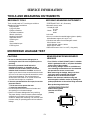
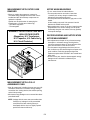
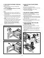
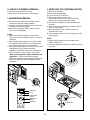
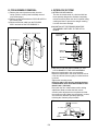
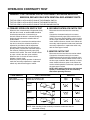
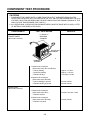
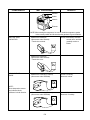
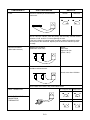
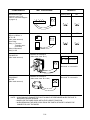
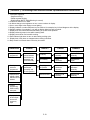
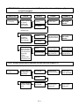
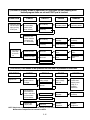
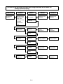
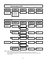
MICROWAVE OVEN
SERVICE MANUAL
MODEL : MB-394A, MH-594A
CAUTION
BEFORE SERVICING THE UNIT, READ THE
SAFETY PRECAUTIONS IN THIS MANUAL.
SERVICE INFORMATION
TOOLS AND MEASURING INSTRUMENTS
NECESSARY TOOLS
NECESSARY MEASURING INSTRUMENTS
Tools normally used for TV servicing are sufficient.
Standard tools are listed below.
¥ Diagonal pliers
¥ Long nose pliers
¥ Phillips screwdriver
¥ Flat blade screwdriver
¥ Wrench (size 5mm)
¥ Nutdriver (size 5mm)
¥ Adjustable wrench
¥ Soldering iron
¥ Solder
¥ Vinyl insulation tape
¥ Polishing cloth
¥ TESTER(VOLTS-DC, AC., Ohmmeter)
¥ Microwave survey meter
- Holaday HI-1500
HI-1501
- Narda 8100
8200
¥ Inch scale
¥ 600 cc non conductive material beaker (glass or plastic),
inside diameter: approx. 8.5 cm(31/2 in.)
¥ Cylindrical and made of borosilicate glass vessel.
max. thickness: 3 mm
outside diameter: approx. 190mm
height: approx. 90mm
¥ Glass thermometer: 100¡C or 212¡F (1 deg scale)
MICROWAVE LEAKAGE TEST
CAUTIONS
MEASURING MICROWAVE ENERGY
LEAKAGE
¥ Be sure to check microwave leakage prior to
servicing the oven if the oven is operative prior to
servicing.
¥ The service personnel should inform the
manufacture importer, or assembler of any
certified oven unit found to have a microwave
emission level in excess of 5 mW/cm2 and should
repair any unit found to have excessive emission levels
at no cost to the owner and should ascertain the cause
of the excessive leakage. The service personnel
should instruct the owner not to use the unit until the
oven has been brought into compliance.
¥ If the oven operates with the door open, the service
personnel should:
- Tell the user not to operate the oven.
- Contact the manufacturer.
¥ The service personnel should check all surface and
vent openings for microwave leakage.
¥ Check for microwave leakage after every servicing.
The power density of the microwave radiation leakage
emitted by the microwave oven should not exceed
4 mW/cm2. Always start measuring of an unknown field
to assure safety for operating personnel from radiation
leakage.
¥ Pour 275±15cc of 20±5¡C(68±9¡F) water in a beaker
which is graduated to 600 cc, and place the beaker
on the center of the turntable.
¥ Set the energy leakage monitor to 2,450 MHz and
use it following the manufacturer's recommended
test procedure to assure correct result.
¥ When measuring the leakage, always use the 2inch (5cm) spacer supplied with the probe.
¥ Operate the oven at its maximum output.
¥ Measure the microwave radiation using and
electromagnetic radiation monitor by holding the
probe perpendicular to the surface being measured
Move probe along shaded area
Probe scanning speed
Less than 2.5 cm/sec
( 1in/sec)
5-1
MEASUREMENT WITH OUTER CASE
REMOVED
NOTES WHEN MEASURING
¥ Do not exceed meter full scale deflection.
¥ The test probe must be removed no faster than
1 inch/sec (2.5 cm/sec) along the shaded area,
otherwise a false reading may result.
¥ The test probe must be held with the grip portion of the
handle.
A false reading may result if the operator's hand is
between the handle and the probe.
¥ When testing near a corner of the door, keep the probe
perpendicular to the surface making sure the probe
horizontally along the oven surface, this may possibly
cause probe damage.
¥ When you replace the magnetron, measure for
microwave energy leakage before the outer case is
installed and after all necessary components are
replaced or adjusted.
Special care should be taken in measuring the
following parts. (Circled area of below Fig.)
- Around the magnetron
- The waveguide
WARNING : AVOID CONTACTING ANY
HIGH VOLTAGE PARTS
(Magnetron, H.V. Transformer,
H.V. Capacitor, H.V. Cable AssÕy,
H.V. Circuit Protector)
RECORD KEEPING AND NOTIFICATION
AFTER MEASUREMENT
¥ After adjustment and repair of any microwave energy
interruption or microwave energy blocking device,
record the measured values for future reference. Also
enter the information on the service invoice.
¥ The microwave energy leakage should not be more
than 4 mW/cm.sq. after determining that all parts are in
good condition, functioning properly and genuine
replacement parts which are listed in this manual have
been used.
¥ At least once a year, have the electromagnetic energy
leakage monitor checked for calibration by its
manufacturer.
MEASUREMENT WITH A FULLY
ASSEMBLED OVEN
¥ After all components, including the outer case, are fully
assembled, measure for microwave energy leakage
around the door viewing window, the exhaust opening,
and air inlet openings.
¥ Microwave energy leakage must not exceed the values
prescribed below.
NOTE: Leakage with the outer case removedless than
5 mW/cm.sq. Leakage for a fully assembled
oven (Before the latch switch (primary) is
interrupted) with the door in a slightly opened
position-less than 2 mW/cm.sq.
5-2
MEASUREMENT OF MICROWAVE POWER OUTPUT
¥ Microwave power output measurement is made with
the microwave oven supplied at its rated voltage and
operated at its maximum microwave power setting with
a load of (1000±5) g of potable water.
¥ The water is contained in a cylindrical borosilicate glass
vessel having a maximum material thickness of 3 mm
and an outside diameter of approximately 190mm.
¥ The oven and the empty vessel are at ambient
temperature prior to the start of the test.
¥ The initial temperature (T1) of the water is (10±2)¡C It
is measured immediately before the water is added to
the vessel. After addition of the water to the vessel,
the load is immediately placed on the center of the
turntable which is in the lowest position and the
microwave power switched on.
¥ The time T for the temperature of the water to rise by a
value Æ T of (10±2)¡K is measured, where T is the time
in seconds and ÆT is the temperature rise. The initial
and final water temperatures are selected so that the
maximum difference between the final water
temperature and the ambient temperature is 5¡K.
¥ The microwave power output P in watts is calculated
from the following formula :
P=
4187 X (DT) + 0.88 X (T2 - T0) X M
T
¥ T2: Temperature after heating
¥ T0: Temperature after bowl
¥ M: Weight of bowl
is measured while the microwave generator is
operating at full power. Magnetron filament heat-up
time is not included. (about 3 sec)
¥ The water is stirred to equalize temperature throughout
the vessel, prior to measuring the final water
temperature.
¥ Stirring devices and measuring instruments are
selected in order to minimize addition or removal of
heat.
WATER LOAD
TURNTABLE
DISASSEMBLY AND ADJUSTMENT
A. OUTER CASE REMOVAL
C. CONTROL PANEL ASSEMBLY
1) Disconnect the leadwire from the PCB SUB ASSÕY.
2) Remove the screws for the earth and securing the
control panel.
3) Lift control panel ASSÕY from the oven by the tab
unhooked.
1) Disconnect the power supply cord from the outlet.
2) Remove the screws from the rear and along side
edges of the case.
The outer case must be moved backward to be lifted
off.
B. POWER SUPPLY CORD
1) Remove the outer case.
2) Disconnect two terminals, and remove one screw of
the earth terminal.
CAUTION: DISCHARGE THE HIGH VOLTAGE
CAPACITOR BEFORE SERVICING
(refer to page 2-1)
5-3
D. DOOR GROSS ASSEMBLY REMOVAL
E. HIGH VOLTAGE TRANSFORMER
REMOVAL
1) Open the door.
2) Remove the choke cover cap very carefully with a
flat-blade screwdriver.
CAUTION : Be careful not to damage door seal plate
by screwdriver.
3) Lift up and push the door.
1) Discharge the high voltage capacitor.
2) Disconnect the leadwire from magnetron, high voltage
transformer, and capacitor.
3) Remove the screw holding the high voltage
transformer to the baseplate.
NOTE:
1. After replacing the door, be sure to check that the
primary switch, monitor switch, and secondary switch
operate normally.
2. After replacing the door, check for microwave energy
leakage with a survey meter. Microwave energy must
be below the limit of 5 mW/cm. (with a 275 ml water
load)
3. When mounting the door assembly to the oven
assembly, be sure to adjust the door assembly parallel
to the chassis. Also adjust so the door has no play
between the inner door surface and oven frame
assembly. If the door assembly is not mounted
properly, microwaves may leak from the clearance
between the door and the oven.
F. FAN MOTOR ASSEMBLY REMOVAL
1) Discharge the high voltage capacitor.
2) Disconnect the leadwire from fan motor, noise filter
and high voltage capacitor.
3) Remove the two screws holding the the suction guide
ASSÕY to the oven cavity and remove the high voltage
diode earth screw.
4) Remove the screw of the capacitor bracket.
5) Remove the two screws holding the fan motor ASSÕY
to the suction guide ASSÕY.
G. HIGH VOLTAGE CAPACITOR AND
DIODE REMOVAL
1) Discharge the high voltage capacitor.
2) Disconnect the leadwire from fan motor, noise filter
and high voltage capacitor.
3) Remove the screw holding the suction guide ASSÕY to
the oven cavity and remove the high voltage diode
earth screw.
4) Remove the screw holding the high voltage capacitor
bracket.
Remove choke cover cap
Fan Motor ASS'Y
Suction
Guide
H.V.
Transformer
Remove door
H.V.
Capacitor
H.V.
Diode
Door seal plate
5-4
H. AIR DUCT ASSEMBLY REMOVAL
J. REMOVING THE TURNTABLE MOTOR
1) Disconnect the leadwire from lamp.
2) Remove the mounting screw to Latch Board.
1) Remove the turntable.
2) Remove the Rotating Ring.
3) Lay the unit down on its back.
4) Remove the turntable motor cover.
The turntable base cover is easily removed by
pinching the six parts with a wire cutting.
5) Disconnect the leadwire from the turntable motor
terminals.
6) Remove the screw securing the turntable motor to
the oven cavity ASSÕY
7) After repairing the motor, rotate the removed
turntable motor cover.
8) Fit the turntable motor coverÕs projecting part to the
base plate slit.
I. MAGNETRON REMOVAL
1) Disconnect the leadwire from the high voltage
transformer and high voltage capacitor.
2) Carefully remove the mounting screws holding the
magnetron and the waveguide.
3) Remove the magnetron ASSÕY until the tube is
clear from the waveguide.
NOTE:
1. When removing the magnetron, make sure its
dome does not hit any adjacent parts, or it may be
damaged.
2. When replacing the magnetron, be sure to install
the magnetron gasket in the correct position and
be sure that the gasket is in good condition.
3. After replacing the magnetron, check for microwave
leakage with a survey meter around the
magnetron. Microwave energy must be below the
limit of 5 mW/cm2. (With a 275 ml. water load).
Make sure that gasket is rigidly attached to the
magnetron. To prevent microwave leakage,
tighten the mounting screws properly, making sure
there is no gap between the waveguide and the
magnetron.
NOTE:
1. Remove the wire lead from the turntable motor
VERY CAREFULLY.
2. Be sure to grasp the connector, not the wires, when
removing.
Magnetron
Waveguide
Dome
Waveguide
Bracket
Magnetron
Gasket
Magnetron
Wire Leads
Turntable Motor
5-5
K. PCB ASSEMBLY REMOVAL
L. INTERLOCK SYSTEM
1) Remove the control panel assembly from the
cavity. (Refer to control panel assembly removal
on previous page.)
2) Remove screws which hold the PCB SUB ASSÕY to
the control panel.
3) Disconnect the flat cable from the PCB SUB
ASSÕY and take off the PCB SUB ASSÕY.
1) INTERLOCK MECHANISM
The door lock mechanism is a device which has
been specially designed to eliminate completely
microwave activity when the door is opened during
cooking and thus to prevent the danger resulting
from the microwave leakage.
2) MOUNTING OF THE PRIMARY/MONITOR/
SECONDARY SWITCHES TO THE LATCH
BOARD
Control Panel PCB Sub ASS'Y
ADJUSTMENT
DIRECTION
Key Membrane
PRIMARY
SWITCH
MONITOR
SWITCH
SECONDARY
SWITCH
3) INSTALLATION AND ADJUSTMENT OF THE
LATCH BOARD TO THE OVEN ASSEMBLY
¥ Mount the latch board to the oven assembly.
¥ Adjust the latch board in the arrow direction so that
oven door will not have any play in it when the door
is closed.
¥ Tighten the mounting screw.
¥ Check for play in the door by pushing the door
release button. Door movement should be less
than 0.5 mm. (1/64 inch)
Don't push the door release button while making
adjustment. Make sure that the latch moves
smoothly after adjustment are completed and that
the screws are tight. Make sure the primary, monitor,
and secondary switches operate properly by
following the continuity test procedure.
FIG. 1
CAUTION: CHECK THE CORRECT POSITION
MAGNETRON
H.V. TRANSFORMER
H.V.
DIODE
H.V. CAPACITOR
PRIMARY
5-6
CIRCUIT PROTECTOR
INTERLOCK CONTINUITY TEST
WARNING : FOR CONTINUED PROTECTION AGAINST EXCESSIVE RADIATION
EMISSION, REPLACE ONLY WITH IDENTICAL REPLACEMENT PARTS.
TYPE NO. SZM-V 16-FA-63 OR VP-533A-OF FOR PRIMARY SWITCH
TYPE NO. SZM-V 16-FA-62 OR VP-532A-OF FOR MONITOR SWITCH
TYPE NO. SZM-V 16-FA-63 OR VP-533A-OF FOR SECONDARY SWITCH
B. SECONDARY INTERLOCK SWITCH TEST
A. PRIMARY INTERLOCK SWITCH TEST
Disconnect the wire lead from the secondary
switch.
Connect the ohmmeter leads to the common
(COM) and normally open (NO) terminals of the
switch. The meter should indicate a open circuit in
the door open condition. When the door is closed,
meter should indicate an closed circuit. When the
secondary switch operation is abnormal, make the
necessary adjustment or replace the switch only
with the same type of switch.
When the door release button is depressed slowly
with the door closed, an audible click should be
heard at the same time or successively at
intervals. When the button is released slowly, the
latches should activate the switches with an
audible click.
If the latches do not activate the switches when
the door is closed, the switches should be a
adjusted in accordance with the adjustment
procedure. Disconnect the wire lead from the
primary switch. Connect the ohmmeter leads to
the common (COM) and normally open (NO)
terminal of the switch. The meter should indicate
an open circuit in the door open condition.
When the door is closed, the meter should
indicate a closed circuit.
When the primary switch operation is abnormal,
make the necessary adjustment or replace the
switch only with the same type of switch.
COMPONENTS
SWITCHES
(Wire leads removed)
C. MONITOR SWITCH TEST
Disconnect the wire lead from the monitor switch.
Connect the ohmmeter leads to the common
(COM) and normally closed (NC) terminals of the
switch. The meter should indicate closed circuit in
the door open condition. When the door is closed,
meter should indicate an open circuit. When the
monitor switch operation is abnormal, replace with
the same type of switch.
NOTE: After repairing the door or the interlock
system, it is necessary to do this continuity
test before operating the oven.
TEST PROCEDURE
Check for continuity of the
switch with an Ohm-meter
Primary
Switch
Monitor
Switch
Secondary
Switch
RESULTS
Door
open
NO
COM
NC
COM
NO
COM
NOTE : After checking for the continuity of switches, make sure that are
connected correctly.
5-7
Door
closed
COMPONENT TEST PROCEDURE
CAUTIONS
1. DISCONNECT THE POWER SUPPLY CORD FROM THE OUTLET WHENEVER REMOVING THE
OUTER CASE FROM THE UNIT. PROCEED WITH THE TEST ONLY AFTER DISCHARGING THE HIGH
VOLTAGE CAPACITOR AND REMOVING THE WIRE LEADS FROM THE PRIMARY WINDING OF THE
HIGH VOLTAGE TRANSFORMER. (SEE PAGE 2-1)
2. ALL OPERATIONAL CHECKS WITH MICROWAVE ENERGY MUST BE DONE WITH A LOAD (1 LITER
OF WATER IN CONTAINER) IN THE OVEN.
COMPONENTS
HIGH VOLTAGE
TRANSFORMER
(Wire leads removed)
TEST PROCEDURE
RESULTS
FILAMENT
WINDING
TERMINAL
SECONDARY
TERMINAL
PRIMARY
TERMINAL
1. Measure the resistance.
(Ohm-meter scale: Rx1 and Rx100)
¥ Primary winding
¥ Secondary winding
¥ Filament winding
Approx.: 2.5 ohm
Approx.: 110 ohm
Less than: 0.4 ohm
2. Measure the resistance.
(Ohm-meter scale: Rx1000)
¥ Primary winding to ground
¥ Filament winding to ground
Normal: Infinite
Normal: Infinite
MAGNETRON
(Wire leads removed)
1. Measure the resistance.
(Ohm-meter scale: Rx1)
¥ Filament terminal
Normal: Less than 1 ohm
2. Measure the resistance.
(Ohm-meter scale: Rx1000)
¥ Filament to chassis
Normal: Infinite
5-8
COMPONENTS
TEST PROCEDURE
RESULTS
Antenna
Gasket
Chassis
Filament
NOTE: When testing the magnetron, be sure to install the magnetron gasket
in the correct position and be sure that the gasket is in good condition.
HIGH VOLTAGE
CAPACITOR
HIGH VOLTAGE
DIODE
NOTE :
Some inexpensive meters
may indicate infinite
resistance in both direction.
Measure the resistance.
(Ohm-meter scale: Rx1000)
¥ Terminal to terminal.
Normal: Momentarily indicates
several ohms, and then
gradually returns to
infinite.
Measure the resistance.
(Ohm-meter scale: Rx1000)
¥ Terminal to case.
Normal: Infinite.
Measure the continuity (Forward).
(Ohm-meter scale: Rx10000)
Normal: Continuity.
Abnormal: Infinite.
Measure the continuity (Reverse).
(Ohm-meter scale: Rx10000)
Normal: Infinite.
Abnormal: Continuity.
5-9
COMPONENTS
FUSE
TEST PROCEDURE
Check for continuity of the fuse with an
multi-meter.
RESULTS
Normal
Abnormal
NOTE: If the fuse is blown, check the primary, the secondary, and the monitor
switches, H.V.D. and H.V.C. before replacing the fuse.
If the fuse is blown by improper switch operation replace the defective switch
and the fuse at the same time. Replace just the fuse if the switches operate
normally.
HEATER ELEMENT
(Wire leads removed.)
Measure the resistance.
(Multi-meter scale: Rx1)
Normal:
*Grill heater
Approx. 50 ohm
(at 20 ~ 30oC)
Measure the resistance with 500V-100M ohm
insulation resistance meter.
Normal: more than 0.5 Mohm
NOTE: Make sure heater is fully cooled when tested.
0¡C~Approx.90¡C Approx.90¡C
GRILL THERMOSTAT
OVEN THERMOSTAT
MAGNETRON
THERMOSTAT
0¡C~Approx.145¡C Approx.145¡C
5-10
COMPONENTS
Disconnect the 8 pin
connector from P.C.B.
(Refer to schemetic diagram
on page 4-3)
RELAY 2, RELAY 3
OF P.C.B.
(Wire leads removed.)
Note: Relay
Relay 1: Fan motor
Turntable motor
Oven lamp
Relay 2: Microwave
Relay 3: Grill
FAN MOTOR
(Wire leads removed)
TEST PROCEDURE
1
3
5
7
RESULTS
Cooking Start
OFF
Cooking Start
OFF
8
Relay 3
Relay 2
Measure the resistance.
(Ohm-meter scale: R x 1)
Normal:
A~B
A~C
30 ~ 50½ 300~500½
Abnormal: ° or several ½
A
B
C
TURNTABLE
MOTOR
(Wire leads removed)
Measure the resistance.
(Ohm-meter scale: R x 1000)
Normal: Approx. 100~200 ½
Abnormal: ° or several ½
NOTE : ¥ A MICROWAVE LEAKAGE TEST MUST ALWAYS BE PERFORMED WHEN THE UNIT IS
SERVICED FOR ANY REASON.
¥ MAKE SURE THE WIRE LEADS ARE IN THE CORRECT POSITION.
¥ WHEN REMOVING THE WIRE LEADS FROM THE PARTS, BE SURE TO GRASP THE
CONNECTOR, NOT THE WIRES.
5-11
TROUBLE SHOOTING
WHEN YOU GET A COMPLAINT FROM YOUR CUSTOMER, EVALUATE THE COMPLAINT CAREFULLY. IF
THE FOLLOWING SYMPTOMS APPLY, PLEASE INSTRUCT THE CUSTOMER IN THE PROPER USE OF THE
MICROWAVE OVEN. THIS CAN ELIMINATE AN UNNECESSARY SERVICE CALL.
CAUTIONS
1. Check grounding before checking for trouble.
2. Be careful of the high voltage circuit.
3. Discharge the high voltage capacitor. (See page 2-1)
4. When checking the continuity of the switches or of the high voltage transformer, disconnect one lead wire
from these parts and then check continuity with the AC plug removed. To do otherwise may result in a
false reading or damage to your meter.
5. Do not touch any part of the circuitry on the digital programmer circuit since static electric discharge may
damage this control panel.
Always touch yourself ground while working on this panel to discharge any static charge built up in your
body.
CONDITION
CAUSE
REMEDY
Microwave oven
does not work.
Inserting many plug into one
plug outlet and using
them at the same time
(causes overloading).
Avoid using other electrical
appliances when you use the
microwave oven.
Microwave oven plug is not
inserted tightly.
Insert microwave oven plug
securely.
Low AC input voltage.
Use the microwave oven at
adequate line voltage.
Food temperature is too low.
This may not be a defect.
It is possible that the food
should be cooked for a
longer time period.
Using metallic ware and
allowing it to touch the oven
wall.
Do not use metallic ware for
cooking except where noted
in the cooking guide.
Ceramic ware trimmed in
gold or silver powder is used.
Do not use any type of
cookware with metallic
trimming.
Inconsistent intensity of
microwave by their
characteristics.
1. Wrap the thinner part with
aluminum foil.
2. Use plastic wrap or lid.
3. Stir once or twice while
cooking soup, cocoa or
milk, etc.
Output power is too low.
Sparks occurring.
Uneven cooking.
5-12
(TROUBLE 1) The following visual conditions indicate a probable defective control circuit.
1. Incomplete segments.
¥ Segment missing.
¥ Partial segment missing.
¥ Digit flickering (NOTE: Slight flickering is normal.)
2. Colon does not turn on or blink.
3. A distinct change in the brightness of one or more numbers in display.
4. One or more digits in the display are not lighting.
5. Display indicates a number different from one touched, for example, key in 5 and 3 appears in the display.
6. Specific numbers (for example 7 or 9) will not display when key pad is touched.
7. Display does not count down with time blinking or up with clock operation.
8. Display obviously jumps in time while counting down.
9. Display counts down too fast while cooking.
10. Each indicator light does not turn on after setting cooking cycle.
11. Display time of day does not reappear when cooking is finished.
12. Beep sound is not heard when correct key is touched.
CONDITION
CHECK
1. No input can be
programmed.
Check the connection between
membrane key
assembly and
PCB assembly.
Continuity.
Defective PCB
assembly.
Replace PCB
assembly.
No continuity.
Loose
connection.
Connect them
tightly.
Replace key
membrane
assembly and
check operation.
Everything works
as specified.
Defective key
membrane
assembly.
Replace key
membrane
assembly.
Defective PCB
assembly.
Replace PCB
assembly.
2. Some inputs
cannot be
programmed.
3. Display shows a
number or figure
different from one
touched.
RESULT
Still have trouble.
4. Random
programming
when touching
other pads.
5. Display is fixed
at some figure
and can not
accept any
input.
5-13
CAUSE
REMEDY
(TROUBLE 2) Oven does not operate at all ; Display window does not display any figures and
no input is accepted.
CONDITION
1. Fuse blows.
CHECK
Check continuity
of monitor
switch (with
door closed).
RESULT
Continuity.
CAUSE
REMEDY
Malfunction of the
monitor switch.
Replace primary
and monitor
switches.
No continuity.
Replace fuse
Check continuity
of primary
switch (with
door opened).
Disconnect one
side of the wire
lead connected
from transformer
to the high
voltage
capacitor and
operate the unit.
Shorted contact at
the primary switch.
Replace primary
and monitor
switches.
Normal.
Defective high
voltage capacitor.
Replace high
voltage capacitor.
Fuse blows again
Defective high voltage transformer.
Replace high voltage transformer.
Continuity.
No continuity.
NOTE : All these switches must be replaced at the same time. Refer to page 5-6, 5-7
2. Fuse does not
blow.
Check continuity
of magnetron
thermostat.
No continuity.
Defective magnetron thermostat.
Replace magnetron thermostat.
Defective power
supply cord.
Replace power
supply cord.
Continuity.
Check continuity
of power supply
cord.
No continuity.
5-14
(TROUBLE 3) Display shows all figures set, but oven does not start cooking while
desired program times are set and START pad is touched.
CONDITION
CHECK
1.Setting time does
not count down
when touching
START pad.
Check continuity
of secondary
switch (with
door closed).
CAUSE
REMEDY
Defective
secondary switch.
Replace
secondary switch.
No continuity.
Defective P.C.B
assembly.
Replace P.C.B
assembly.
Continuity.
Loose connection.
Connection then
tightly.
Check fan motor.
Abnormal.
Defective fan
motor.
Replace fan
motor.
Check oven lamp.
Abnormal.
Defective fan
motor.
Replace fan
motor.
Check the connection between
connector and
P.C.B assembly.
2. Fan motor or
oven lamp
do not turn
on.
RESULT
No continuity.
continuity.
Normal.
(TROUBLE 4) Oven seems to be operation but little heat is produced in oven load.
CONDITION
Output is low.
CHECK
Check the
power source
voltage.
RESULT
CAUSE
REMEDY
Lower than 90% of
rating voltage.
Decrease in power
source voltage
with load.
Suggest customer
contact local
electric power
utility co. or
qualified
electrician.
Normal.
Disconnect the
wire leads from
relay 2 and check
on and off time
with multitester.
Abnormal.
Defective P.C.B
assembly.
Replace P.C.B
assembly.
Measure the
output power.
Abnormal.
Defective
magnetron.
Replace
magnetron.
NOTE: Simple test of power output-conducted by heating one liter water for one min. if available.
Minimum 8.5oC temperature rise is normal condition.
5-15
(TROUBLE 5) No microwave oscillation even though oven lamp and fan motor run
(Display operates properly)
CONDITION
No microwave
oscillation.
CHECK
Disconnect the
wire leads from
relay 2 and
check continuity
of relay2.
(Operate the
unit)
Check H.V.
transformer.
RESULT
No continuity.
CAUSE
REMEDY
Defective P.C.B
assembly
Replace P.C.B
assembly
Defective high
voltage
transformer.
Replace high
voltage
transformer .
Defective high
voltage capacitor.
Replace high
voltage capacitor.
Defective high
voltage Diode.
Replace high
voltage Diode.
Defective
magnetron.
Replace
magnetron .
Continuity.
Abnormal
normal
Check H.V.
capacitor.
Abnormal
normal
Check H.V.
diode.
Abnormal
normal
Check
Magnetron.
Abnormal
5-16
(TROUBLE 6) Oven does not cook properly when programmed for the set power level
(Operates properly on HIGH)
CONDITION
CHECK
Output is full when
you set lower
power level.
Disconnect the
wire leads from
relay 2 and check
continuity relay 2.
(Operate the unit)
RESULT
Abnormal.
CAUSE
Defective P.C.B.
assembly.
REMEDY
Replace P.C.B.
assembly.
(TROUBLE 7) Grill
CONDITION
1. Heater is not
operating.
CHECK
Heater.
RESULT
Abnormal.
CAUSE
REMEDY
Malfunction the
heater.
Replace.
Malfunction the
thermostat.
Replace.
Normal.
Thermostat and
relay(Grill).
Abnormal.
Normal.
1. Lower temperature the oven.
Wire connection.
No continuity.
Open or loosen.
Replace or
connect tightly.
Heater.
Abnormal.
Malfunction the
heater.
Replace.
Malfunction the
thermostat.
Replace.
Normal.
Thermostat and
relay(Grill).
Abnormal.
NOTE: * Make sure the wore leads correct position.
* When removing the wire leads from parts be sure to grasp the connector not the wires.
* When removing the magnetron, be sure to install the magnetron gasket in the correct position and in
good condition.
5-17