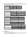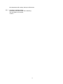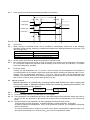
1
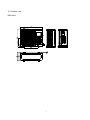
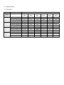
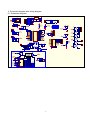
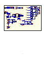
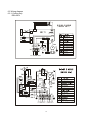
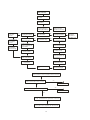
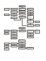
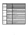
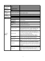
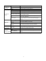
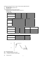
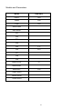
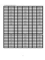
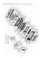
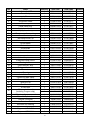
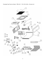
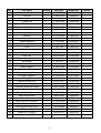
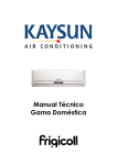
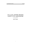
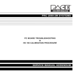
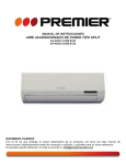
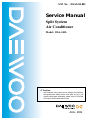
S/M No : DSA241L001
Service Manual
Split System
Air Conditioner
Model: DSA-241L
✔ Caution
: In this Manual, some parts can be changed for improving,
their performance without notice in the parts list. So, if you
need the latest parts information, please refer to PPL(Parts
Price List) in Service Information Center.
AUG., 2006
Contents
1. Features………………………………………………………………… 02
2. Specification………………………………………………………..……03
3. Dimensions…………………………………………………………..… 04
4. Refrigeration cycle diagram……………………………………………06
5. Capacity table…………………………………………………………...07
6. Wiring diagram…………………………………………………..………08
7. Troubleshooting………………………………….………….…………..11
8. Electronic function…………………………………………………… .17
9. Characteristic of temp. sensor…………………………………………23
1
1.Features
1.1 Compact design
1.2 LED display
2
16
54
P14RE5245 (Interna)
950
YDK36-4C
Welling
150
2µ
1200/1120/1080/1000
1080/1020/960/880
1080X330X225
YDK53-6D
Welling
800
2500
≤
56/60
R22 / 1450
ø
m
m
°C
°C
ø
20
10
3.Dimensions
3.1 Indoor unit
DSA-241L
4
3.2 Outdoor unit
12.5
DSA-241L
5
4.Refrigeration cycle diagram
6
5. Capacity table
5.1 DSA-241L
SUMMER
OUTDOOR TEMPERATURE DRY
Indoor
25ºC
30ºC
35ºC
40ºC
45ºC
50ºC
Total capacity kW
6.57
6.25
5.81
5.34
4.90
4.57
Sensitive capacity kW
4.61
4.47
4.28
4.06
3.85
3.69
Input kW.
2.30
2.50
2.71
2.95
3.13
3.35
Total capacity kW
7.04
6.73
6.35
5.94
5.55
5.22
Sensitive capacity kW
4.89
4.75
4.58
4.41
4.28
4.23
Input kW.
2.30
2.52
2.75
2.98
3.21
3.44
Total capacity kW
7.54
7.40
7.00
6.45
5.87
5.37
Sensitive capacity kW
5.30
5.19
5.12
4.75
4.51
4.30
Input kW.
2.34
2.58
2.80
3.05
3.29
3.52
Total capacity kW
7.98
7.80
7.69
7.42
7.08
6.73
Sensitive capacity kW
5.24
5.09
5.04
4.96
4.90
4.92
Input kW.
2.41
2.59
2.87
3.15
3.42
3.70
Conditions
21ºC D
15ºC W
24ºC D
17ºC W
27ºC D
19ºC W
32ºC D
23ºC W
7
6. Schematic diagram and wiring diagram
6.1 Schematic diagram
IC3
1
C3
104
VCC
WC
SCL
SDA
1
2
3
4
A0
A1
A2
GND
+5V
TRANS_OUT
R7 12K
C8
FUSE1
1000uF/25V
L
E1
D6
+5V
0.1uF/275VAC
1
3
2
R2
10K
2200uF/25V
RST
+5V
C2
104
IC1 KIA7042
R1
10K
J1
EEPROM
R5
R6
10K
SW1
J2
C7
104
J2
+12V D9
Model
SW_TEST
10K
TRANS_IN
PTC1
82RM
+5V
D8
C1
104
2
t
N
POWER
104
12VAC1
1
C16
ZR1
14D681K
1
C5
CN5
3.15A/250V
470uF/16V
+12V
D5
L1
CN2
2
D4
12VAC2
1
E3
104
D7
3
+5V
3
Vout
104
5VAC1
4
2
C6
2
8
7
6
5
SCL
SDA
E2
D3
CN1
7805
Vin
D2
5VAC2
IC2 24C04
R4
10K
GND
D1 IN4007*8
+5V
R3
10K
无
冷暖
无掉电记忆
有
单冷
有掉电记忆
In_FanLL'
J1
1
+5V
In_FanLL
+5V
2K
In_FanLL'
2
C10
104
D13
IN4148
1
T1_room
R11
2K
T1_room
R17
8.1K/1%
CN8
D14
E4
C9
IN4148
10uF/16V
104
In_FanM
In_FanH
STEP_I1
STEP_I2
STEP_I3
STEP_I4
HEAT
+5V
SEG5
SEG1
SEG2
SEG3
SEG4
2
D15
IN4148
1
+5V
T2_I.pipe
R12 2K
In_FanM
In_FanH
STEP_I1
STEP_I2
STEP_I3
STEP_I4
HEAT
SEG5
SEG1
SEG2
SEG3
SEG4
T2_I.pipe
R18
8.1K/1%
D16
E5
C11
IN4148
10uF/16V
104
R19
1M
IC4
T1
T1_room
T2
T2_I.pipe SW
SW_TEST
Model
Model
1
2
3
4
5
6
7
8
9
10
11
12
13
14
15
16
17
18
19
20
21
VSS
VDD
P25
P26
P00
P01
P02
P03
P04
VSS1
P05
P50
P51
P52
P53
AVDD
AVREF
ANI0
ANI1
ANI2
ANI3
X1
X2
RESET
XT1
XT2
Vpp/IC
P24
P23
P22
P21
VDD1
P20
P33
P32
P31
P30
P11
P10
AVSS
ANI5
ANI4
X1
42 X1
41 X2
40 Reset
39
38
37
36
35
34 RXD20
33 TXD20
32
31
30 BUZ
29 In_FanL
28 In_FanLL
27 REC
26 SDA
25 SCL
24
23
22
RST
REC
C14
RxD20
TxD20
102
R22
3.5K/3W
CN12
1
R24
5.1k
D18
N
ZD1
E6
C15
473
100uF/35V
IN4749
R23
100K
C17
471/250v
STEP_I1
STEP_I2
In_FanH
RxD20
C19
C20
101
4.7K
R27
R25
330
IC6
L1
1N4007
R21
11K/2W
11K/2W
DIS1
WT4021BG
TxD20
2k
+5
SEG3
DTA143
com1
com2
h
g
f
e
d
c
b
a
SEG2
C20
104
+5
GND
Q7
Vcc
Q6
Q5
R59
9
10K
8
C16
101
SEG4
R60
10K
SEG5
2
C17
101
E7
47UF/16V
IC8
7
14
1
MR
Q4
CP
Q3
Q2
Dsb
Q1
Dsa
Q0
74HC164
13
+5
150 R19
12
11
10
6
5
4
3
R45
330
R46
330
R47
330
R48
330
R49
330
R54
330
R55
330
Q3
9014
In_FanM'
L1
RY5
FAN_IN H
5
IN1
OUT1
IN2
OUT2
IN3
OUT3
IN4
OUT4
16
1
In_FanH'
15
2
OUT5
IN6
OUT6
11 In_FanM'
IN7
OUT7
10 In_FanL'
VDD
9
R9
1K
4
IN5
VSS
CN10
1
HEAT_N
7
UJN2003
L1
LOAD_HEAT N
3
13
12
CN11
+12V
14
In_FanH'
5
RY6
HEAT N
BUZ1
N
+12VSWING
LOAD_HEAT L
R16
BUZ
Q5
9014
REC1
C11
104
REC1
1
2
3
LED6
AUTO
LED7
DEF.
LED8
TIMER
LED9
RUN
显示板原理图
8
CN13
1
HEAT_L
RY7
HEAT L
2K
HEAT'
L
R14
Q10
E8
100UF/16V
4
+12V
NPN
SEG1
Q9
DTA143
3
8
+5
Q8
DTA143
2
In_FanM 6
In_FanL
Q4
R20
1
C12
104
PC851
D17
RY4
M
IC7
STEP_I4
1N4007
L1
HEAT'
IN4148
2K
EEPROM
101
5
CON5
+12VD11
HEAT
+5V
+5
In_FanL'
104
STEP_I3
PC817
RY3
L
R14
BUZ
In_FanL
In_FanLL
REC
SDA
SCL
R15 2k
C13
104
S
C18
4
N
1
2
3
4
5
6
7
8
+5V
+5V
IC_UPD789166(42PIN)
IC5
R8 1K REC1
3
L1
CN9
SEG4
SEG3
SEG2
SEG1
SEG5
2
RY1
LL
Q1
9014
R13
CN7
CN6
+12V
IN4148
IC1
+12V
1
D2
E1
D3
7805
+5V
3
Vout
CN4
E2
104
5VAC2
3
2
1
Vin
C1
GND
D1 IN4007*8
5VAC1
CN1
1
104
AC_L
1000uF/25V
470uF/16V
L1
CN6
3.15A/250V
ZR1
14D681K
CN5
TRANS_OUT
D5
4148
FUSE1
2
D4
L
C2
C3
1
0.1uF/275VAC
2
t
N
1
COMP
COMP
CN8
+12V
2
1
1
RL1
L1
TRANS_IN
CN9
1
D6
4148
VALVE
CN10
1
3
F_OUT1
2
R9
F_OUT1
CN11
1
Q5
9014
R15
RL4
2k
2K
R5
8.1K/1%
D9
E4
C6
IN4148
10uF/16V
104
CN13
IC2 IC/UPD78F9116
+5V
+5V
C7
104
R8
Current
C5
104
相序C
相序B
相序A
T3
Current
D10
1N4148
R6 2K
5.1K/1%
D11
R7
1N4148
16K
R10
1K/1%
E3
100uF/16V
R39 330
CT1
0057U
+5V
LED1
压力开关
F_OUT2
相序C
相序B
相序A
1
2
3
4
5
T3
CURRENT 6
7
8
9
10
指示灯
11
12
13
14
压力开关
1
P23/INTP0 P22/RxD20
P24/INTP1 P21/TxD20
P25/INTP2 P20/ASCK20
AVDD
P11
P60/AN10
P10
P61/AN11
VDD
P62/AN12
VSS
P63/AN13
X1
AVSS
X2
P50
IC
P51
RESET
P52
P03
P53
P02
P00
P01
28
27
26
25
24
23
22
21
20
19
18
17
16
15
RX
TX
RX
TX
单相启动
曲轴箱
+5V
单相启动
曲轴箱
X1
F_OUT2
R12
1M
X1
X2
Reset
COMP
VALVE
F_OUT1
RL5
D13
4148
Q4
9014
R14
F_OUT2
L1
2k
CN12
1
2
RST
COMP
VALVE
F_OUT1
D12
4148
F_OUT2
曲轴箱
Q3
9014
R13
曲轴箱
2k
+5V
10K
相序C
IC3
R19
相序C
C10
104
+5V
R16
R24
D14
R11 12K
1
3
2
IC6 KIA7042
D17
4148
RST
C11
104
单相启动
68K/2W
2K
C8
104
PC817
2k
相序B
IC4
10K
R20
PC817
R18
相序A
J10
R25
68K/2W
2K
C9
104
相序A
N
D15
L
Q7
NPN
R27
TX
TX
CN14
相序B
2K
IC8
1
2
3
4
RX
RX
IC7
R28
2k
R35
5.1K
+5V
R32
10K
压力开关
C15
104
CN16
F2
压力开关
J9
1
9
PC817
471/250V
R29
D18
1N4007
104
CN3
1
C12
5.1K
C18
101
+5V
1
R31
3.5k/3W
C13
+5
C17
101
CN15
F1
PC851
R38
330
4007
R23
5.1K
+5V
10K
Q6
9014
R30
单相启动
4007
R22
5.1K
+5V
R17
F_OUT2
L1
T3
1
T3
F_OUT1
L1
D7
4148
+5V
4
D8
IN4148
333
L1
RL3
R4
10K
R3 VALVE
51/1W
C4
Q2
9014
R2
VALVE
RL2
2k
CN2
COMP
2k
PTC1
82RM
AC_N
CN7
Q1
9014
R1
S
N
N
曲轴箱
6.2 Wiring diagram
6.2.1 Cooling only
DSA-241L
WIRING DIAGRAM
(INDOOR UNIT)
UNIT2
TRANS1
CN1
XS2 XP2
CN8
UNIT1
FUSE 3.15A/250V
RT1
CN2
CN6
CN10
CN11
RT2
CN7
RED
BLUE
WHITE
Y/G
XT1
CN
CN9
1
5
FAN1
M
~
SWING SWING
S
AG
CAP1
TO OUTDOOR UNIT
CN1
CN2
CN11
CN10
CN6
UNIT1
CN3
CN4
CN5
CN8
TO INDOOR UNIT
POWER SUPPLY
10
Y/G
7.troubleshooting
The following tables will help to find where error happened (LED on indoor unit):
For models adopting electrical function
Operation
Timer
Defrosting
lamp
lamp
lamp
☆
☆
☆
☆
X
☆
X
X
☆
X
X
X
X
X
☆
X
X
X
☆
☆
EEROM error
X
☆
X
☆
Indoor unit communication err
X
X
X
☆
Failure phenomenon
Over current protection of the compressor
occurs 4 times
Indoor room temp. sensor is open circuit or
short circuit
Temp. sensor on indoor evaporator is open
circuit or short circuit
Auto lamp
Temp. sensor on outdoor condenser is open
circuit or short circuit (without for cooling only
models)
Outdoor unit protects(outdoor temp sensor,
phase order etc)
r Extinguish
☆ Flash at 5Hz
NOTE: For cool only model, the defrosting lamp is replaced with fan lamp, but malfunction display remains.
11
Cur r ent p rotectio n
(LED indi cates)
Check t he indoor
air filt er.
Check the out door
condenser.
Che ck t he positio n
and wiring of tem p
sen sor (all of the m).
Check sp eed
of in door
motor.
Che ck speed
of o utdoo r
mo tor.
Recycle the
refrigerant
and recharge .
Yes
Does ind oor heat exchan g er frosted?
If wro ng, t he unit w ill
result in current
prote ction, not tem p.
Yes
D oes it occur in
C ool mode?
No
Does outdo o r heat exchanger fr osted?
Yes
It is n orma l under
tha t ambient temp .
Yes
Doe s the ind oor
o
temp low than 1 0 C?
No
Doe s the outdoo r
o
temp over 48 C?
Yes
No
No
No
Check t he overcurre n t prot ect or of
comp ressor.
Check t he solenoid
coil o f reve rse valve.
Check t h e soft
starter m ou ld.
C heck the soft
st arter mou ld.
Re place the
ma in PCB board .
C heck t he ove rc urre nt prot ect or of
c ompressor.
Re place the
co mpressor.
Replace th e
main PCB board.
R eplace the re verse
v alve.
Recycle the ref rig erant and rec h arge.
Indoor /Outdoor Units C ommunic ation Pr otection
No
Is the L&N c onnections betwe en
indoor and outdoor units corr ec t?
Re conne ct cor re ctly.
Yes
No
Is the c omm unic ation conne ction good?
Re conne ct cor re ctly.
Yes
Re place the outdor PC B, the n run th e m ac hine.
Is the com mu nica ti on pro tec tion re lie ved?
Yes
It m ean s t h at t h e mal fu n c t i o n i s
fr om indoor unit. Re pla ce the indoor PC B.
12
Che ck t he
dra inage
sys tem of
out door unit.
T he unit does not
o per ate
Per f orm
the related
inst ruct io ns.
Yes
Do th e LED lamps
indicat es ERR?
Ye s
Does the power LED
light af ter turning
the switch on?
No
Ch eck t he bat ter y
of the remot er.
Check the po wer
supplie r.
Check t he displa y
board .
Chec k wirin g.
No
Is th ere beep from
the unit when using
remoter?
Yes
Yes
Replace the
disp lay boa rd .
Does the unit run in
Forced Co ol m ode?
No
Rep lace the ma in
PCB b oard.
Ch eck t he soft
sta rter
No
No
C heck t he elect rical
so urce.
Does the volt ag e
bet wee n inpu t
terminat es o f
transformer i s
corre ct?
Yes
Does the volt ag e
bet wee n outp ut
terminat es o f
transformer i s
corre ct?
No
Replace the
transfo rmer.
Yes
No
D oes the power
tr ansfer to t he
di sp lay boa rd ?
Yes
Replace the
disp lay boa rd .
No
Does it just happ en
in th e beginning of
coolin g or heat in g
mode?
Yes
It is b ecaus e
of the h eat
rub be tween
plastics parts.
It is n orma l.
Abnormal n o ise
from the indoor unit
Check t he
swing mo to r.
Yes
Does it happ en with
aut o swing?
Yes
Does it happ e n in
Fan On ly mod e?
No
Check t he
swing lou ver .
Check t he fa n
motor .
No
Check the inp ut
and output pip e.
Check t he cross flow
fan .
R ecycle the ref rig er ant and recha rge.
Replace the b ear.
Ab normal noise
fro m the outdoo r
uni t
Check t he
motor.
Yes
Do th e fan blade rub
with t he shroud?
No
Check t he
fan blad e.
Check t he
motor
supporter.
C heck t he fixing nut s
of outdoo r unit.
Yes
D oes it happ en in
C ool mode?
No
Check t he capillary.
C heck t he
co mpressor.
13
Re cycle the ref rig eran t and recharg e.
PROBLEM
Not operating
Indoor abnormal
noise.
CAUSE
Power failure
Wiring failure
Transformer failure
Indoor PCB failure
Cross flow fan failure
Loose screws
Worn bearings
Motor failure
Fan blade failure
Loose screws
Outdoor abnormal Motor failure
noise.
Compressor failure
Copper tubing
REMEDY
Check the power cord.
Check the wiring. Replace the terminates or wires if failure.
Check the input and the output on transformer. Replace if
failure.
Replace after checked failure.
Replace the fan if cracked, out of balance, or partially
missing
Tighten them.
Replace after checked failure.
Replace the motor if knocking sounds continue when
running or loose, or the motor hums or noise appears to be
internal while running.
Replace the fan blade if cracked, out of balance, or partially
missing.
Tighten them.
Replace the motor if knocking sounds continue when
running or loose, or the motor hums or noise appears to be
internal while running.
Replace the compressor if sounds coming from inner of the
compressor.
Remove the cabinet and carefully rearrange tubing not to
contact cabinet, compressor.
Display board or indoor
PCB failure
Remote control
failure.
Compressor
protection
Replace the display board. If it is still false, replace the PCB.
Check the voltage of battery. Replace batteries if the voltage
Battery failure
is lower than 2.3V.
Normally, the remote control is not easy to damage. If the
Remote control failure
above two methods are not effectual, replace the remote
control.
Check leakage. Recycle the refrigerant. Correct and
Lack of refrigerant
recharge if there is any leakage in the refrigerant system.
Check the module and the capacitor connected to the
Soft starter module failure
module. Replace if failure.
Overcurrent protector
Check the resistance of compressor overcurrent protector.
failure
Replace if failure.
Outdoor PCB failure
Replace after checked failure.
14
PROBLEM
Open or short
circuit of outdoor
temperature
sensor
Room temp or
evap temp sensor
open or short
circuit
Over load or too
low voltage
protection
Fan speed
beyond control
Zero-crossing
error
Insufficient
cooling or
heating.
CAUSE
Temperature sensor
failure
Connector failure or loose
Outdoor PCB failure
Temperature sensor
failure
Connector failure or loose
Indoor PCB failure
REMEDY
Replace after checked failure.
Repair or replace the sensor.
Replace after checked failure.
Replace after checked failure.
Repair or replace the sensor.
Replace after checked failure.
Check the module and the capacitor connected to the
Soft starter module failure
module. Replace if failure.
Power failure
Wait if checked the power voltage is really too low.
Wiring failure
Correct if indoor fan motor wiring is loose.
Indoor fan motor failure
Check the input of fan motor. Replace if failure.
Indoor PCB failure
Replace after checked failure.
Indoor PCB failure
Replace after checked failure.
Air filter
Clean or replace if restricted.
Determine if the unit is properly sized for the area to be
Unit undersized
cooled or heated.
Condenser and
Clean or replace if restricted.
Evaporator
Take proper measures to make the door and windows
Room structure
sealed well if gap is found.
Clean or remove if any barrier is found to block the
Air flow
inlet/outlet wind flow of the unit.
Sunlight
Add a awning if the outdoor unit is exposed to the sunlight.
Check the fan capacitor on outdoor power control board and
replace the board if not within +/-10% of manufacturer's
Outdoor fan motor
rating. Replace the motor if the speed is not within +/-10% of
manufacturer's rating but not because of the capacitor.
indoor fan motor
Less refrigerant
Capillary tube
Compressor
Heat sources
reverse valve
For electrical function 2.3 models. Check the fan capacitor in
indoor electric box (for some models, the capacitor is on
main PCB.) and replace the capacitor (or main PCB) if not
within +/-10% of manufacturer's rating.
Replace the motor if the speed is not within +/-10% of
manufacturer's rating but not because of the capacitor.
Check the tubes for reasons of leakage. Recycle the
refrigerant, correct the leakage points and recharge.
Regulate the flow if capillary tube is blocked. Make the
evaporating temperature appropriate if the evaporator is
frosted.
The inlet and outlet valve of the compressor is damaged,
making the low pressure connected with the high pressure.
The refrigerating system is difficult to produce high pressure
and low pressure. Replace the compressor after checking for
the reason.
Reduce if over loaded.
The two paths for refrigerant are connected, making the low
pressure connected with the high pressure. The refrigerating
system is difficult to produce high pressure and low
pressure. Replace the reverse valve after checking for the
reason
15
PROBLEM
No display on
indoor unit.
CAUSE
LED failure
Remote control shut the
display
No power
Wiring
Temperature setting
Mode setting
REMEDY
Replace the display if checked failure.
Push the button to turn the display on.
Check the voltage. Call an electrician if not within the limit.
Check the terminals. Repair and correct if loose.
Check and adjust the temperature setting.
Check and adjust the mode setting.
Check the module and the capacitor connected to the
No cooling or
Soft starter module failure
module. Replace if failure.
heating.
Reverse valve solenoid
Check the reverse valve solenoid coil. Replace the coil if
coil
short, open or damaged.
If the reverse valve is blocked, the heating mode will not
Reverse valve
perform. Replace the reverse valve after checking the
reason.
Water drainage failure
Check the drainage pipe and repair if failure.
The indoor unit is incorrect
Correct the installation if not correct.
Water drops from installed
indoor unit
Drainage pipe blocked
Correct it.
The humidity in room is
It's normal if the humidity in the room is over 85%.
too high
Wiring failure
Check wiring. Correct if wrong wiring or loosen.
Check wiring. Correct if the commucication wire is not
Wire EMC
shielded wire or twisted with other wires.
Zero-crossing
Outdoor PCB failure
Replace if the LED is not on.
error
Outdoor transformer
Replace if failure.
failure
Insufficient
Replace the PCB if the photon coupling on indoor PCB is
Indoor PCB failure
cooling or heating.
failure.
Indoor PCB failure
Replace after checked failure.
16
8. Electronic Control Principle of Large Cooling Capacity Split Model A/C
8.1 Fan only mode
Fan speed is high/mid/low/ Auto
8.2 Cooling mode
The 4-way valve is closed at cooling mode.
The action of the compressor and the outdoor fan:
T: Room temp.
Ts: Setting temp.
Condition
Temp. up
Temp. down
Compressor
Outdoor fan
T> Ts+1
On
On
T<Ts+1
Off
Off
T> Ts
On
On
T<Ts
Off
Off
Auto fan
Condition(T=Indoor Temp.-Setting Temp.)
Temp. up
Temp. down
Indoor fan speed
T<1℃
Low
1℃ <T<4℃
Med.
T>5℃
High
T> 4℃
High
1℃ <T<4℃
Med.
T<1℃
Low
Anti-freezing control to indoor evaporator
Condition
Temp.
Temp. up
Compressor
T> TE6
T< TE6
Temp. down
>4 Minutes
T> TE5
T< TE5
>4 Minutes
On
On
Off
Off
On
On
Off
Off
Condenser high temp. protection( only for heat pump)
Temp. Condition
Temp. up
Temp. down
Compressor
T> TE10
Off
T< TE10
On
T> TE11
Off
T< TE11
On
The outdoor fan motor speed control in the cooling mode.
T3
32
High speed
30
Low speed
8.3 Dehumidifying mode
8.3.1 Indoor fan speed at low speed.
8.3.2 Protection is same as cooling mode.
8.4
Outdoor fan
Time
Heating mode
17
8.4.1
8.4.2
8.4.3
Generally, the 4-way valve is open in heating mode, but it is closed in defrosting mode.
Generally, the outdoor fan is turned off with the on-off action of compressor in heating mode, except
for the defrosting mode or the end of defrost.
Action conditions of compressor at heating mode: compressor must run for 4 minutes after starting
and then judge temperature. Meanwhile other protections are still valid.
Condition
Room temp. up
Room temp. down
8.4.4
Compressor
Outdoor fan
T> Ts+4
Off
Off
T<Ts+4
On
On
T< Ts+3
On
On
T>Ts+3
Off
Off
Indoor Fan actions at heating mode
Indoor Fan can be set at HIGH/MID/LOW/AUTO by using a remote controller,
Anti-cold wind function 1.
Condition
Indoor fan speed
T= Indoor exchanger temp.
Indoor exchanger temp. up
Indoor exchanger temp. down
T<TE1
Off
TE1<T<TE2
Low speed
T>TE2
Setting fan speed
T>TE3
Setting fan speed
TE4<T<TE3
Low speed
T>TE4
Off
Anti- cold air protection 2 ( when the room temp. satisfy the setting temp.)
T=evaporator pipe sensor temp.
Indoor fan speed
Room
temp. up
T<TE14+2℃
Low speed or stop
T> TE14+2℃
Setting speed.
Room
temp. down
T> TE14
Setting speed.
T< TE14
Stop after 15 seconds Low speed
Condition
Indoor fan speed
Auto wind
T=Indoor Temp.-Setting Temp.
Room
Room
temp. up
temp. down
T<2℃
Med. speed
T>2℃
Low speed.
T> 0℃
Low speed.
T<0℃
Med. speed
Indoor evaporator high-temperature protection
Condition
Compressor
Outdoor fan
T= Indoor exchanger temp.
Indoor exchanger temp. up
Indoor exchanger temp. down
T<TE15=54℃
On
On(high speed)
TE15<T<TE8
On
On(low speed)
TE8<T<TE7
On
Off
T>TE7
Off
Off
T>TE9
Off
Off
T<TE9
On
On
8.5
Defrosting mode
8.5.1 Conditions of defrost:
Defrosting starts when either of the following :
T3 lower than 0°c, lasts for more than 40 minutes, provided that the time period when the temperature
is lower than -3°c consecutively reaches 3 minutes.
Calculate from the end of latest defrost, evaporator high temp. protection only closes outdoor fan with
18
the compressor still running. Add up to 90 minutes
.
8.5.2
Conditions of defrost ending:
Defrosting ends when either of the following :
The time gets to 10 minutes;
T3>20°c
19
8.5.3
Time sequence of the whole defrosting procedure is as follows:
Defrost 10or 6minutes
55S
55S
Compressor
4-way Valve
50S
50S
Outdoor Fan
Indoor Fan
15S
Remark: when the evaporator pipe sensor temp. more than TE16, The indoor fan start to run.
8.6
8.6.1
Auto mode
When running in automatic mode, the air conditioner automatically selects one of the following
operation modes: cooling, heating or ventilation according to the difference between room temp. (TA)
and set temp. (TS).
TA—TS
Operation mode
TA—TS>2℃
Cooling
-1℃ ≤TA—TS≤+2℃
Air-only
TA—TS<-1℃
Heating (air-only for cooling only type)
8.6.2
8.6.3
At auto mode, the indoor fan blows automatically in selected mode.
One mode should be carried out for at least 15 minutes once selected. If the compressor cannot start
for 15 minutes, reselect the operation mode according to the room temp. and set temp., or reselect
when the setting temp. changed
8.7
Economic mode
Cooling: The set temperature rise 1℃ per hour. Two hours later, the set temperature will maintain as
a constant and the air circulation is kept at low speed,and the air condition will stop work after 7 hours.
Heating: The set temperature decrease 1℃ per hour. Two hours later, the set temperature will
maintain as a constant and the air circulation is kept at low speed, and the air condition will stop work
after 7 hours. (Cold air proof function takes priority over all).
8.8
Manual operation
Manual operation is controlled by touching buttons and divided into force cooling and
forced auto mode. It transfers between these two modes by pressing the buttons, the
cycling order of the button press is:
Remote mode
Forced auto
Forced cooling
8.8.1 Forced Cooling
8.8.1.1 In forced cooling mode, the remote signal is not accepted.
8.8.1.2 The compressor is unconditionally turned on, after 30 minutes cooling operation whose fan mode is
set as low, the A/C operates in the forced auto mode under the requirements of the forced auto
mode.
8.8.1.3 During the start-up and operation, all of the following protecting functions work:
3minutes start-up delay protection, overload protection, outdoor protection, evaporator
Protection against low temperature. If any of the protection functions, the comparative protecting
action is executed.
The forced cooling mode is closed by one touch on the button, meanwhile the operation light is off,
the buzzer buzzes lasts for 1 seconds, then A/C turns to be closedown status.
20
8.8.2. Forced Auto
8.8.2.1 Remote control signal can be received in forced auto mode. When receiving the signals, the
forced auto mode will be canceled and the A/C changes to remote control status and performs
operation as the signals indicates.
8.8.2.2 The system performs control according to the remote control auto mode with a set temperature of
24°c.
8.9
Timer
24 hours timer on or off.
8.10 Protecting Function
8.10.1 Compress with a delay of 3 minutes.
8.10.2 Sensor open and break protection
8.10.3 EEPROM error protection.
8.10.4 Current protection function.
Condition
Current up
Indoor fan
Compressor
Outdoor fan
Remark
I< IRESTORE
On
On
On
IRESTORE <I< IFAN
On
On
Off
Heating mode
Low speed
On
On
Cooling mode
IFAN <I<I5MIN
Off
Off
After 5 Minutes
I5MIN<I< I3SEC
Off
Off
After 3 Seconds
Current
I5MIN<I< I3SEC
Off
Off
After 3 Seconds
down
IFAN <I<I5MIN
Off
Off
After 5 Minutes
On
On
Off
Heating mode
Low speed
On
On
Cooling mode
On
On
On
IRESTORE <I< IFAN
I< IRESTORE
8.11 Auto restart Function
In case of a sudden power failure, this function automatically sets the unit to previous
settings before the power failure when power returns.
21
Models and Parameters
Model
DSA-241L
I3SEC
14A
I5MIN
20A
IFAN
22A
IRESTORE
IDEFROST
TE1
TE2
TE3
TE4
TE5
2°C
TE6
12°C
TE7
TE8
TE9
ANGLCOOL
67
ANGLHEAT
ANGLOFF
130
THDEFROST
TMDEFROST
TLDEFROST
22
9. Characteristic of temp. sensor
Temp.℃
Resistance KΩ
Temp.℃
Resistance KΩ
Temp.℃
Resistance KΩ
-10
62.2756
17
14.6181
44
4.3874
-9
58.7079
18
13.918
45
4.2126
-8
56.3694
19
13.2631
46
4.0459
-7
52.2438
20
12.6431
47
3.8867
-6
49.3161
21
12.0561
48
3.7348
-5
46.5725
22
11.5
49
3.5896
-4
44
23
10.9731
50
3.451
-3
41.5878
24
10.4736
51
3.3185
-2
39.8239
25
10
52
3.1918
-1
37.1988
26
9.5507
53
3.0707
0
35.2024
27
9.1245
54
2.959
1
33.3269
28
8.7198
55
2.8442
2
31.5635
29
8.3357
56
2.7382
3
29.9058
30
7.9708
57
2.6368
4
28.3459
31
7.6241
58
2.5397
5
26.8778
32
7.2946
59
2.4468
6
25.4954
33
6.9814
60
2.3577
7
24.1932
34
6.6835
61
2.2725
8
22.5662
35
6.4002
62
2.1907
9
21.8094
36
6.1306
63
2.1124
10
20.7184
37
5.8736
64
2.0373
11
19.6891
38
5.6296
65
1.9653
12
18.7177
39
5.3969
66
1.8963
13
17.8005
40
5.1752
67
1.830
14
16.9341
41
4.9639
68
1.7665
15
16.1156
42
4.7625
69
1.7055
16
15.3418
43
4.5705
70
1.6469
23
Exploded View Parts for Model DSA-241L 220~240V, 60Hz: Indoor Unit
24
No
1
2
3
4
5
6
7
8
9
10
11
12
13
14
15
16
17
18
19
20
21
22
23
24
25
26
27
28
29
30
31
32
33
34
35
36
37
38
39
40
41
Name
Indicator for LED
Panel Ass’y
air filter
Air cleaner
Air cleaner holder
Screw cap
Panel frame assy
display board holder
display board assy
Window cover for repairing
Air out frame assy
Horizontal louver, up
Horizontal louver, down
Air out frame
Drain Hose
Grille holder
Vertical louver
Louver motor
evaporator
Indoor temp sensor
Evaporator temp sensor
Bearing holder
Cross flow fan, assy
Fixing part for motor
Fan motor
Chassis
Installation Plate
Connecting pipe clamp
Fan motor capacitor
Wire joint, 5p
Transformer
E-Parts box
Main control board
(including Program chip)
Wire clamp for power cord
Cover for E-parts box
Remote Controller
Holder, Remote Controller
connector for watering
seal
Copper nut, TLM-B02
Copper nut,TLM-D04
Quanlity
1
1
2
1
1
3
1
1
1
1
1
1
1
1
1
3
15
1
1
1
1
1
1
1
1
1
1
1
1
1
1
1
1
1
1
1
1
1
1
1
1
1
25
Sale code
13518111001
13528111001
13528111002
10109121226
10109121225
13528111003
13528111004
13518111007
13518111008
15021111006
13821111002
13528111006
13528111007
13528111010
10118121223
10321121006
13528111012
10105111047
10924121003
15021111014
10109121242
10321111008
10321111009
10321111013
13521311001
15021111015
10321111011
10321111015
50309121808
10124121203
10118121232
15021111016
13821111005
13407111026
10121121234
15021111017
11608111003
10718121009
11609121003
31009321021
10909121013
11324113804
BOM code
2113029215
2113079316
2113079315
2113010212
2113010217
2113079313
2113079317
2113029159
2333029078
2113079250
2113079320
2113079568
2113079569
2113079567
2110109002
2113079145
2113079570
2240020004
2153079031
2243079040
2243069051
2273079001
2110029010
2113079045
2240040720
2113079242
2123079017
2123079016
2240119015
2230145023
2230099003
2113079200
2133079129
2130073660
2113070033
2113079249
2335506565
2113139022
2110102011
2272009001
2160032001
2160032003
Remark
Exploded View Parts for Model DSA-241L 220~240V, 60Hz : Outdoor Unit
26
No.
1
2
3
4
5
6
7
8
9
10
11
12
13
14
15
16
17
18
19
20
21
22
23
24
25
26
27
28
29
30
31
32
33
34
35
36
37
Part Name
Clamp for front net
Front net
Front clapboard
Propeller fan
Fan Motor
Holder for fan motor
Foam over holder for motor
Front right clapboard
Chassis
Compressor
Separating board
Little Handle
Cover
Condenser
Left clapboard
Rear Net
Rear right clapboard
Big Handle
Installation plate for valves
Water collector
Capacitor Clamp
Compressor capacitor
Fan motor capacitor
Wire joint
Washer for wire joint
Clamp for wiring
Installation board for E-parts
Contactor
Wire joint for multiplexer
Main control board
Transformer
High Pressure Valve Ass’y
Liquid pipe valve
Low Pressure Valve Ass’y
Low Pressure Valve
Copper nut, TLM-B02
Copper nut,TLM-D04
Quantity
8
1
1
1
1
1
1
1
1
1
1
1
1
1
1
1
1
1
1
1
1
1
1
1
1
1
1
1
1
1
1
1
1
1
1
1
1
27
Sale code
10112121801
10118121801
10924121801
10118121804
13521311801
10118121809
10118121807
10118121803
10122113803
10122123804
10118111806
10830121811
10118121827
13521111801
10924121808
10924121809
10118113804
10118121817
10118113805
10118121832
10112121814
10122123801
10109121819
11812113810
10112121817
10118121823
13821111803
10121121806
10121121809
13528111802
11018121010
10124111815
10124121812
10122113804
10124121814
10909121013
11324113804
BOM code
2113511801
2124550017
2124550030
2114550002
2240041637
2124550020
2224550001
2124551101
2124550022
2140061720
2123530551
2115029006
2124550031
2153549096
2124550032
2114550004
2123549024
2114550003
2123500018
2113529005
2120010002
2240100805
2240110351
2230145021
2113500004
2124540027
2123549049
2230085004
2230145035
2133549001
2230090080
2163549418
2160074223
2163549312
2160072219
2160032001
2160032003
Remark
PH360X3CS-3KUU1
DAEWOO ELECTRONICS CORP.
686, AHYEON-DONG MAPO-GU SEOUL, KOREA
C.P.O. BOX 8003 SEOUL, KOREA
TELEX: DWELEC K28177-8
CABLE: “DAEWOOELEC”
PRINTED DATE: AUG., 2006