Download User Manual
Transcript
User Manual Invacare Rea Azalea Wheelchair English Assist Base Tall Minor Max ©Invacare Rea AB Every effort has been made to ensure that the contents of this publication are updated at the time of printing. As part of the ongoing improvement of the products, Invacare Rea AB reserves the right to modify existing models at any time. Any use of this publication, or parts thereof, as well as any reproduction of images, must have the written consent of Invacare Rea AB 2 Azalea R CONTENTS 1. GENERAL 1.1 Introduction 1.2 Symbols 1.3 Warranty 1.4 Limitation of liability 1.5 Copyright protection 1.6 Customer service 1.7 Accidents/near accident 1.8 Testing 1.9 Intended use 4 4 4 4 4 4 4 4 4 5 2. SAFETY 2.1 Lifting The Wheelchair 2.2 Daily performance check 2.3 Specific risks 6 6 6 6 3. TECHNICAL DATA 3.1 Dimensions and weight 3.2 Upholstery and frame colours 3.3 Equipment and accessories 3.4 Seat height table 3.5 Identification label 7 7 8 8 9 10 4. SET-UP AND INSTALLATION 4.1 Delivery check 4.2 Wheelchair overview 4.3 Assembly 11 11 11 11 7. TRANSPORT 7.1 Transporting wheelchairs with users in vehicles 7.2 Restraint methods 7.3 How to disassemble your Azalea® 37 37 39 8. MAINTENANCE 8.1 Safety Information 8.2 Maintenance schedule 8.3 Cleaning 42 42 42 43 9. AFTER USE Recycling 44 44 40 5. COMPONENTS AND ADJUSTMENTS 13 5.1 Backrest 13 5.2 Backrest för azalea max 14 5.3 Angle settings 15 5.4 Carer-operated angle adjustment 15 5.5 Electric tilt /backrest angle adjustment 16 5.6 Armrests 17 5.7 Seat 18 5.8 Legrests 19 5.9 Foot plate/calf pad/ foot rest 21 5.10 Push handles/push bar/push bar 24 5.11 Rear wheels 25 5.12 Brakes 27 5.13 Anti-tip devices 28 5.14 Azalea base 29 5.15 Accessories 30 6. USING THE WHEELCHAIR 6.1 Move to/from the wheelchair 6.2 Stretching and leaning 6.3 Propelling up a slope 6.4 Propelling down a slope 6.5 Climbing a kerb 6.6 Kerbs – alternative method 6.7 Escalators and stairs Azalea R 34 34 34 34 35 35 36 36 3 1. General 1.1 INTRODUCTION Rea® Azalea is a wheelchair with many adjustment possibilities and accessories. To ensure that you benefit as much as possible from Rea® Azalea, and in order to do its options justice, the chair must be tested and adjusted by competent personnel. We hope that you have also received instructions for using your Rea® Azalea in everyday life. This manual includes a description of the parts of the chair, simple adjustment options, how to use the Rea® Azalea safely and how to transport it. The manual must be read thoroughly before the wheelchair is used. Also included in this manual is a description of how accessories are fitted and slightly more advanced settings. As the Rea® Azalea has many different components and accessories, the appearance of the accessories you have for your chair may differ from those shown. 1.2 SYMBOLS AND SIGNAL WORDS Symbols and signal words are used in this manual and apply to hazards or unsafe practices which could result in personal injury or property damage. See the information below for definitions of the signal words. Warning Warning indicates a potentially hazardous situation which, if not avoided, could result in death or serious injury Caution Caution indicates a potentially hazardous situation which, if not avoided, may result in property damage or minor injury or both Important Indicates a hazardous situation that could result in damage to property if it is not avoided 1.4 LIMITATION OF LIABILITY Invacare Rea AB accepts no liability for damage arising from: Non-compliance with the User Manual Incorrect use Natural wear and tear Incorrect assembly or set-up by the purchaser or a third party Technical modifications Unauthorised modifications and/or use of unsuitable spare parts The written authorisation of Invacare Rea AB must be obtained before installing additional adaptations on a Invacare Rea wheelchair. Otherwise no liability claims can be made. 1.5 COPYRIGHT PROTECTION All information quoted is believed to be correct at time of print. Invacare® reserves the right to alter product specifications without prior consultation. Rea, Rea design and DSS (Dual Stability System) design are registered trademarks of Invacare® International. 1.6 CUSTOMER SERVICE For contact details please refer to the last page of this publication where you will find addresses to the european sales companies. 1.7 ACCIDENTS/NEAR ACCIDENTS Please inform your Invacare office immediately of any accidents or near-accidents that have been caused by this wheelchair and that have led to, or could have led to, personal injury. The relevant authority must also be contacted and reported to. 1.8 TESTING The Rea® Azalea has been tested and approved by TÜV and is CE-marked according to the Medical Device Directive. 1.3 WARRANTY We provide a two-year guarantee from the delivery date. Damage due to wear and tear on upholstery, tyres, (rubber) tubes, hand rims and castors etc., is not covered by the guarantee. Damage that has been caused through physical violence or abnormal use is not covered. Damage caused by users who weigh more than the maximum user weight stated for each Rea Azalea model is not covered. The guarantee will only apply if the maintenance instructions are followed. 4 Azalea R 1.9 INTENDED USE REA AZALEA GENERAL The Rea® Azalea is a manual wheelchair, intended for passive users, both dependant and semi-dependant, who remain seated for long periods of time. Regarding both operation and adjustment of seating position, the Rea® Azalea is intended for operation by the user or carer. The Rea® Azalea must be used with its seat and backrest pads. The Rea Azalea is intended for use both indoors and outdoors Max. user weight is 135 kg. The service life of the chair depends on its application, the user’s degree of activity as well as care and maintenance. However, if there is an agreement between Invacare and the manufacturer of the seating system that regulates the responsibility between the companies, the product can maintain its CE-marking. In other cases, the company mounting the seating system will be responsible for the CE-marking or that the chair will be registered and documented as a specially made medical technical product. The Rea® Azalea Base has been crash tested together with the Invacare standard back and seat, but no other combinations have been tested and Invacare can in no way predict the effect of an accident with other configurations. Other tests performed on the Azalea Base have also been carried out with the standard back and seat from the Azalea range mounted. 1.10 INTENDED USE REA AZALEA MINOR The Rea® Azalea Minor is intended for smaller adults and teenagers, who are passive users, both semidependant and dependant. Max user weight is 75 kg. Please note that the harness has to be fitted and adjusted by a trained therapist. 1.12 INTENDED USE REA AZALEA MAX The Rea® Azalea Max is intended for larger adults who are passive users, both semi-dependant and dependant. Max user weight is 180 kg. 1.11 INTENDED USE REA AZALEA BASE The Rea® Azalea Base is a part of the Azalea family that is meant as a wheelchair base for different seating systems such as individually adapted anatomic seats manufactured by different companies. The Rea® Azalea Base is intended for use both indoors and outdoors. 1.13 SERVICE LIFE We estimate that the Invacare® wheelchair has a service life span of five years. It is difficult to state the exact length of the service life of our products and the length stated is an estimated average life span based on normal use. The life span may be considerably longer if the wheelchair is used to a limited extent and if it is used with care, maintained and handled properly. The life span may be shorter if the wheelchair is subjected to extreme use. The maximum allowed weight load on the Rea® Azalea Base is 135 kg. This includes both user and seating system. The Azalea range is CE-marked, but since the Rea® Azalea Base is not to be considered as a complete product and it is only when the base and the seating system have been combined that an evaluation of the safety can be done, it rests upon the company that mounts the seating system to perform such an evaluation. Azalea R 5 2. Safety 2.1 LIFTING THE WHEELCHAIR 2.3 SPECIFIC RISKS Below you will find a number of points affecting your personal safety. Read them carefully! Invacare is only responsible for product changes carried out by competent personnel. We reserve the right to make any changes to equipment and specifications without prior notice. Failure to comply with instructions given may result in personal injury and/or product damage. Always lift the wheelchair by grabbing the frame at the points shown in the picture. Never lift the wheelchair by the removable armrests or the footrests. Ensure that the backrest and push handles are securely in place. Also read the chapter Safety instructions/Propelling techniques. 2.2 DAILY PERFORMANCE CHECK Check that the following parts are correctly mounted on the wheelchair: ' $ " + ; 6 wheelchair: – that all parts are attached securely to the frame – that all wheels, knobs, scews and nuts are properly tightened – that all brakes and anti-tip devices function correctly rests, footrests, backbrace or by the adjustable push handles. of the chair. out of the chair, because of the risk of tipping. of tipping over. which may cause injury to your hands. " # " operated brake is reduced in wet and slippery conditions, as well as when on a slope. $ securely attached. % straps on the backrest become too slack. Always check the tension. & upholstery can, after long exposure to the sun, reach temperatures over 41°C. ' * trap your fingers. of your body when tilting the wheelchair’s back and seat. % so much so that the inside of the armrests press against the side of the pelvis. Azalea R 3. Technical data 3.1 DIMENSIONS AND WEIGHT 1. Seat width 2. Seat depth 3. Seat height 6. Legrest length 7. Tilt adjustment 8. Total width 11. Weight 12. Maximum user weight 13. Transport weight 4. Backrest height 5. Armrest height 9. Total height 10. Total length 14. Backrest adjustment AZALEA AZALEA ASSIST AZALEA TALL AZALEA BASE AZALEA MINOR AZALEA MAX 1. 2. 3. 4. 390-550 MM 430-500 MM 400/450 MM 560-790 MM 540-715 MM 390-590 MM 430-500 MM 400/450 MM 560-790 MM 540-715 MM 390-590 MM 480-550 MM 500 MM 560-790 MM 540-715 MM 340-590 MM 380-500 MM 400/450 MM - 340-440 MM 380-450 MM 400/450 MM 550-650 MM 550-710 MM 530-600 MM 400/450 MM 500 MM 5. 6. 7. 8. 9. 10. 11. 12. 13. 14. 240-360 MM 330-500 MM -1° - 25° SW+250 MM 950 - 1020 MM 950 - 1020 MM 34 KG 135 KG 16.5 KG 0° - 30° 240-360 MM 330-500 MM -1° - 25° SW+220 MM 950 - 1020 MM 950 - 1020 MM 34 KG 135 KG 20.5 KG 0° - 30° 240-360 MM 330-500 MM -1° - 25° SW+220 MM 1000 - 1300 MM 950 - 1070 MM 36 KG 135 KG 18.7 KG 0° - 30° 240-360 MM 330-500 MM -3° - 30° SW+220 MM 900 -1300 MM 950 - 1020 MM 20 KG 135 KG 15 KG -3° - 30° 240-360 MM 330-500 MM -1° - 25° SW+ 220 MM 900-1250 MM 900-970 MM 32 KG 75 KG 14.5 KG 0° - 30° 320-420 MM 330-500 MM 1°-23° SW+250 MM 1020-1240 MM 1050-1120 MM 54 KG 180 KG 26 KG 0° - 30° Azalea R 7 3.2 UPHOLSTERY AND FRAME COLOURS Upholstery Black Plush TR35 Black Dartex TR26 Frame colour Pearl Grey, Azurite, Sand, Electric green, Happy red 3.3 EQUIPMENT AND ACCESSORIES Invacare® Rea Azalea has a wide range of accessories and options. Some of the accessories may not be available in all markets or on all models. Backrest Tension adjustable Backrest plate Brake User-brake Carer-operated drumbrake Backrest cover/cushion Lateral cover Laguna (lateral support) cushion Mistral 2 (waist support) cushion Passad 2 (shoulder support) cushion Shoulder High 05 (dartex) cushion Vicair multifunctional cushion Others Headrest Headrest with cheek support Neckrest Trunk support Lumbar support Wedges Pelvic belt Harness Reflectors Table tray Pump Cane holder Push bar Braced push handles Several types of handrims Spoke guard Seat Depth adjustable Sliding seat Seat cushions Floshape Vicair Multifunctional Seat and backrest regulation Assistant operated gas piston seat and backrest tilt Electrical operated seat and backrest tilt Legrests Central legrest Angle adjustable Fixed 80° or 90° Amputee legrest Footplates One piece footrest Fixed Depth and angle adjustable Footboard converter Armrests Height adjustable with standard pad, wide pad or extra padding Hemiplegic armrest Castors 140-200 mm, soft medium or pneumatic Widths 27 -45 mm Rear wheels 16”, 22", 24", pneumatic,puncture-proof or solid 8 Azalea R 3.4 SEAT HEIGHT TABLES 3.4.1 Rea® Azalea & Rea® Azalea Assist 110 1 2 4 3 4 3 2 1 5 45 45 45 40 40 40 40 45 45 45 24" 24" 24" 22" 22" 16" 16" 16" 16" 16" 150 2 2 2 1 1 4 3 2 1 1 2 2 3 3 3 3 1 4 4 3 3 3 2 2 200 150 140 150 140 150 140 200 150 140 3.4.2 Rea® Azalea equipped with Tall-kit 150 4 4 3 2 1 5 50 50 24" 16" 4 5 2 3 200 200 3.4.3 Rea® Azalea Base 110 1 2 4 3 2 1 4 3 5 24" 24" 24" 22" 22" 16" 16" 16" 16" 16" 45 45 45 40 40 45 45 45 40 40 Azalea R 2 2 2 1 1 3 3 3 150 4 3 2 1 1 2 2 3 3 1 2 2 4 4 3 3 200 150 140 150 140 200 150 140 150 140 9 3.4.4 Rea® Azalea Max 110 1 2 3 45 40 45 24’’ 22’’ 16’’ 4 3 2 1 4 3 2 1 2 1 3 150 1 3 1 200 140 200 3.5 IDENTIFICATION LABEL Manufacturing date Model INVACARE International SARL Serial No. Max. user weight Location Location of the identification label. 10 Azalea R 4. Set-up and installation 4.1 DELIVERY CHECK 4.3 ASSEMBLY Any transport damage must be reported immediately to the transport company. Remember to keep the packaging until the transport company has checked the goods and a settlement has been reached. When you receive your wheelchair, you must fit the backrest, armrests and legrests onto the chair. The assembly is simple and does not require any tools. 4.3.1 Backrest 4.2 WHEELCHAIR OVERVIEW 1 D 13 2 3 12 C 11 4 A B 10 5 9 8 7 6 1. Neckrest 2. Backrest 3. Armrest 4. Seat 5. Legrest 6. Castor 7. Brake 8. Rear wheel plate 9. Anti-tip device and step tube 10. Rear wheel 11. Allen key for adjustments (on back of backrest cushion) 12. Handle for backrest angle and seat tilt adjustment 13. Push handle Azalea R The backrest is fitted onto the wheelchair by sliding the profiles (A) of the backrest onto the tubes of the chair (B). make sure that you push the backrest down as far as possible. Secure into place by tightening the knobs (C). On the Azalea Max the pin (D) needs to be secured at the bottom of the backrest. Secure the backrest cushion using the Velcro strips. Now check that the backrest is secured firmly in position! When fitting the push bar/push handles be aware to place the wires outside the handwheels. Otherwise the wires can be damaged. 11 4.3.2 Armrests 4.3.4 Angle adjustable legrests D Attach the armrests by feeding them into the attachment (D) at the sides of the wheelchair. Push them downwards until you can feel that the armrests are securely in place. Attach the legrests by pushing the tube at the upper part of the legrests down into the tubes on the wheelchair. You must angle the legrests outwards when inserting them. Lock the legrests by turning them inwards. The legrests are automatically locked so there is no risk of them coming off the wheelchair. 4.3.5 Fixed legrests 4.3.3 Rear wheels A Attach the rear wheels by pressing button (A) in the centre of the hub whilst simultaneously sliding the axle (B) into the rear wheel position attachment of the positioning plate. It is very important that you check that the locking pin has actually locked the wheel into position when the centre button has been released. Take hold of the wheels and try to detach them. This should NOT be possible. Attach the footrests by pushing the tube at the upper part of the footrests down into the tubes on the wheelchair. You must angle the footrests outwards when inserting them. Lock the legrests by turning them inwards. The legrests are automatically locked so there is no risk of them coming off the wheelchair. 12 Azalea R 5. Components and adjustment 5.1 BACKREST 5.1.1 Bacrest plate Any adjustments made to the backrest should be evaluated by trained personnel. Height Adjustment Width Adjustment A A Warning Risk of breakage If you have seat width 490 mm (max seat width) the backrest should NOT be adjusted to the widest possibility (+100 mm). B C 1. You can easily adjust the backrest plate (+ 130 mm) by loosening the four screws (A) with a 5-mm Allen key. Set at the required height and re-tighten. Warning Risk of pinching When adjusting the height these is a risk of pinching your finger at the point (B) shown in the illustration. For width adjustment, remove screw (B) and loosen screws (C). Adjust to the required width (+25 or 50 mm on each side). Re-insert screw (B) and tighten. Tighten screws (C). C D B 2. For additional height adjustment (90 mm), loosen screw (C) and screws (D) and set the required height. Re-tighten all screws. Azalea R 13 5.1.2 Tension adjustable backrest Any adjustments made to the backrest should be evaluated by trained personnel. 2. Adjust the backrest to the preferred height. Loosen and remove screws (A) and remove bracket (B) before moving the backrest either up or down. Reattach screws and bracket. The tension adjustable backrest must be adapted and adjusted according to the individual needs of the user. The following steps guides you through the adjustment of the backrest. B 1. Determine if the user needs more space in the shoulder area (illustration 1) or in the bottom area (illustration 2). The design of the backrest tubes with different angles allows for these adjustments. 2 1 A A 3. Width and angle adjustment The backrest tubes have a width adjustment of 25 mm. The upper and lower parts of the tubes can be adjusted individually to accomodate for different needs. The outward movement will embrace the user and offer lateral support. Loosen screws (A) and adjust the upper and lower parts of the backrest tubes as needed. Loosen and remove screws (A) on both sides, turn the backrest and reinsert the screws. Make sure to fasten properly. 14 Azalea R 4. Tension adjustable straps Define where you would like to have a firmer support of the back of the user. Have the user leaning forwards and tighten the straps in that region. Make sure that all straps are fastened. Apply the cover (start with the vertical middle) and make sure that the shape now created by the tension adjustable straps is preserved. 5.1.3 Gas piston holder for backrest with plate and tension adjustable backrest Caution Remember to always reinsert and fasten the safety pin when it has been removed. The gas piston holder allows for the terapeut/assistant to loosen the safety pin for the backrest gas piston when folding without the gas piston falling to the ground. Azalea R 15 5.2 BACKREST FÖR AZALEA MAX A B The backrest for the Azalea Max is designed with different angles as shown in picture 1. This allows for different adjustments according to how the backrest is mounted. Position A (the part of the backrest with the longer angle turned upwards) gives the user more room for the shoulder area while position B gives more room for the bottom. 5.2.1 Adjustment 4. 1. A Loosen the handwheels (A) and raise the push handles as far as possible. Turn the backrest 180° 5. 2. Put the backrest back by fitting it to the receivers on the tubes. Tighten the screws. Remove the cushion. 3. Loosen screws (B) and remove the backrest by lifting upwards. 16 6. Put the cushion and cover back. Lower the push handles and tighten the hand wheels. Azalea R 5.3 ANGLE SETTINGS B A C D There is a possibility to change the range of available angles for the seat by changing the position of the gas spring (A) on the chassi attachment (B). This procedure may only be performed by a service technician! Azalea Max can only use hole II (D). Except for the cases where electric tilt and angle controls are used, then ONLY hole I (C) may be used. Other Azalea models might use either hole. Except for the cases where electric tilt and angle controls are used, then ONLY hole 1 (C) may be used. The wheelchair should be tipped over sideways before the gas spring is loosened from the chassi attachment. Otherwise there is a risk of pinching. Angles obtained: Hole I: 16’’ rear wheels -1° - +23° 24 ‘‘ rear wheels -1° - +23° Hole II 16’’ rear wheels +1° - +25° 24’’ rear wheels +1° - +25° Azalea R 17 5.4 CARER-OPERATED ANGLE ADJUSTMENT The wheelchair is equipped with carer-operated controls. You can adjust the angle of the backrest forwards or backwards and tilt the whole seat unit including the backrest. These two functions can either be controlled manually or electrically. Be careful when adjusting the angle of the backrest so that the assistant or user do not trap fingers between the backrest and the armrest. 5.4.1 Backrest angle adjustment 5.4.2 Tilt adjustment A B Use the yellow (A) lever on the left hand side to angle the backrest. Press upwards while you angle the backrest to the desired position, Release the lever. 18 Use the green lever (B) on the right hand side to tilt the seat unit (seat and backrest). Press upwards while you tilt the seat unit to the desired position, Release the lever. Azalea R 5.4.3 Locking device for angle adjustment C D The locking device (C) allows you to set the tilting of the seat unit and/or the angling of the backrest to a fixed position. Tilt and/or angle the seat and backrest to the desired position and insert the locking device. The position is now set and cannot be changed. The locking device is removed by pressing the plastic peg (D) with a small object while pulling outwards. Azalea R 19 5.5 ELECTRIC TILT AND BACKREST ANGLE ADJUSTMENT 5.5.1 Charging the battery 1. 2. B B C C If your wheelchair has electrical angle adjustment the battery needs to be charged. If the angle adjustment function has been used during the day, it is a good idea to leave the charger on overnight. Charge the battery by plugging the battery charger supplied with the chair into a wall socket. Then Insert the the charger cable into the connector which is on the side of the wheelchair as illustrated. It takes about 12 hours to charge a battery that has been used 50% of its capacity. Work on the handset should only be carried out by properly trained personnel. The risk of trapping fingers, etc., is greater in electric adjustments than in user-operated adjustment. Bear in mind, for example, that a child may get hold of the control box, press the controls and get trapped, or trap the user. The hand control should only be used by authorised personnel. Backrest angle adjustment Adjust the angle of the backrest by using the upper part of the control panel. Press (B) to adjust the angle of the backrest forwards or press (C) to adjust the angle backwards. Tilt adjustment Tilt the seat unit (seat and backrest) by using the lower part of the control panel. Press (B) to adjust the angle of the seat unit backwards or press (C) to adjust the angle forwards. 20 Azalea R 5.6 ARMRESTS 5.6.2 Armrest depth 5.6.1 Armrest height A C B Adjust the height of the armrests by turning the knob or Allen key screw (A), setting the required height and then re-tightening the knob/screw. You can also adjust the depth of the armrest pad. Loosen the knob (C), set the pad in the required position and re-tighten the knob. Be aware not to trap your fingers between the armpad and the sidesupport when you adjust the armrest height. 5.6.3 Autolock for armrest The armrests have an auto-lock to prevent involuntary movement or detachment. Press the button (B) on the spring to release before removing or adjusting the armrest. Azalea R 21 5.7 SEAT 5.7.2 Width adjustment B The seat depth of the chair can easily be adjusted to provide good support. The width between the legrests and armrests and the height of the armrests can also be adjusted. 1. The seat cushion is secured with Velcro strips on the seat plate. 5.7.1 Depth adjustment C A Remove the seat cushion and loosen the screws (A) with an Allen key. Move the front edge of the seat forwards or backwards, and retighten the screws. The distance between the back of the knee/calf and the cushion should be as small as possible, but without contact. Replace the seat cushion. a. Loosen the screw (B) with an Allen key. Adjust the armrests to the desired width and retighten the screw. b. Loosen the screws (C) with an Allen key. Adjust the legrests to the desired width and retighten the screws. c. The seat width can be decreased with 2x20 mm by placing cushions inside the armrest pocket. 22 Azalea R 5.8 LEGRESTS 5.8.1 Angle adjustable legrests Angle adjustable legrests support the legs and reduce pressure. The legrests can be used for bandaged legs, but not for legs in plaster casts. The legrests must always be fitted with calf pads, footplates and heel straps. It is important to adjust the height and angle of the legrests to obtain a good seating position. 5.8.1.1 Height adjustment 5.8.1.2 Angle adjustment B A Tools: 5 mm Allen Key C Loosen screw (A) with an Allen key. Adjust the legrest into a suitable height and the screw is caught by one of the recesses on the legrest tube. Then retighten the screw. Pull the lever (B) with one hand while supporting the legrest with your other hand. When a suitable angle is obtained, let go of the lever and the legrest will look into one of seven preset positions (C). For the Azalea Max four different positions ara available, see point 5.7.4 Do not place anything heavy, or let children sit on the legrest. It may cause damage to the mechanism. The distance between the lowest part of the footrest and the ground must be at least 40 mm. Azalea R 23 5.8.2 Fixed legrests, height adjustment 5.8.3.2 Height adjustment B C B You can adjust the height of the legrest in the following two ways: A Alternative 1: Loosen the Allen screw (B) using a 5 mm Allen key on the front of the telescopic tube, place the legrest in the desired position and secure it into place using the Allen screw. Loosen screw (A) with an Allen key. Adjust the legrest into a suitable height and the screw is caught by one of the recesses on the legrest tube. Then retighten the screw. NOTE! Don't touch the upper screw (B). Alternative 2: Loosen the Allen screw (C) by the legrest attachment as shown in the diagram. Adjust to the desired height and then retighten the screw. 5.8.3.3 Foot angle adjustment The distance between the lowest part of the footrest and the ground must be at least 40 mm. D 5.8.3 Central legrest 5.8.3.1 Leg angle adjustment Loosen the rear screw (D) on the side of the tube using a 5 mm Allen key and adjust the legrest to the desired angle. Retighten the screw. Repeat this procedure to adjust the angle of the other legrest. A 5.8.3.4 Depth adjustment Adjust to the appropriate leg angle using knob (A). When adjusting the angle of the central legrest, loosen the adjustment knob with one hand and hold the foot plate with the other hand to avoid trapping yours or anyone else’s fingers etc. When the seat is tilted forwards on a chair with a long legrest length and low seat height, there is a risk of the legrest hitting the floor and causing damage. 24 E Loosen the frontal screw (E) on the side of the tube to adjust the depth of the legrest. Tighten the screw when you have found the desired depth. Repeat this procedure to adjust the depth of the other legrest. Azalea R 5.9 FOOT PLATE/CALF PAD/ FOOT REST 5.9.1 Angle-adjustable footplates 5.9.3 One-piece footrest A A Tool: 5 mm Allen key Adjust the angle and the depth by loosening the screw (A) at the footplate attachment with a 5 mm Allen key. Adjust the footplate to the correct position and retighten the screw. Do not place anything on the footplate when the screw is loose. 1.Adjust the angle and the depth by loosening the two screws (A) at the footplate attachment with a 5 mm Allen key. Adjust the footplate to the correct position and retighten the screws. 5.9.2 Calf pads Do not place anything on the footplate when the screws are loose. B C 2. The footrest can be flipped up. Lift the left side of the footrest upwards. Be careful not to trap your fingers between the footrest and the reciever when folding it down. Tool: 5 mm Allen key The calf pads can be fitted in two different depth positions. Swing the pad forwards. Unscrew screw (B) using an Allen key. Remove the large nut (C) on the reverse side and place it in the other attachment hole. Move the calf pad to the new position and secure it into place with the screw. The height of the calf pads can easily be adjusted using the handwheel (D). Azalea R 25 5.9.4 Legrest Azalea Max 5.9.5 Calf pads for Azalea Max B A D C 1 2 3 4 B C ! Pull the lever (B) with one hand while supporting the legrest with your other hand. When a suitable angle is obtained, let go of the lever and the legrest will lock into one the preset positions (C). For the Azalea Max four different positions are available. The adjustment should be done in accordance with the adjustment of the calf pads. Higher adjustments (marked red) are possible, but NOT recommended as the legrest might not be able to support the added weight. The calf pads for the Azalea Max are adjustable in angle (A), depth (B) and sideways (C). A: Loosen the handwheel and adjust to the required angle B: Loosen the handwheel and adjust the calf pad to the required depth. The adjustment should be done in accordance with the adjustment of the legrest. C: Loosen the screws (D) and adjust the calf pad sideways. Do not forget to tighten the screws properly. Do not place anything heavy, or let children sit on the legrest. It may cause damage to the mechanism. Caution! Risk of pinching When adjusting the calf support there is a risk of pinching your fingers. Make sure that no pressure is on the calf support when the handwheels are loosened. The distance between the lowest part of the footrest and the ground must be at least 40 mm. 26 Azalea R 5.9.6 Footboard converter for Azalea Max A A The footboard converter is a sturdy construction that is easily dissassembled to allow for transfers into and out of the wheelchair. The middle part of the footboard converter is installed by inserting the fasteners into one of the footplates and then on the other side. Make sure that the part is turned the right way. If not, it will fall out. The buttons (A) should pop out when the middle part is installed correctly. The footplates can be flipped up to further facilitate transfers. A To remove the middle part, press the buttons (A). First on one side and then on the other. Make sure that the feet are placed as far out as possible. Make sure that the feet are placed as far out as possible before the middle part is installed or removed. Otherwise the pressure on the footplates might cause the footboard to break. Caution! Risk of pinching When adjusting the footboard there is a risk of pinching your fingers. Make sure that no pressure is on footboard when it is being adjusted. Caution! Risk of breakage The footboard is not designed for lifting the chair. Do not take hold on the footboard if you need to lift the chair. Azalea R 27 5.10 PUSH HANDLES/PUSH BARS The push bar/push handles braced must not be pulled up so that it protrudes more than 19 cm over the top edge of the attachment. Do not trap your fingers between the pushhandles brace and the neckrest attachment. (If you have a tension adjustable backrest). The following instructions and warnings are valid for all three alternatives 5.10.1 Height adjustment A When fitting the push bar/push handles be aware to place the wires outside the handwheels. Otherwise the wires can be damaged. Loosen the knobs (A). The height of the pushhandles braced/pushbar can be adjusted simply by pulling the handles upwards or pushing them downwards. Adjust it to the height that you require and tighten it. It is important that you do not mix up the upper and lower knobs on the back of the backrest. The lower knobs lock the backrest to the chair, and if these are loosened by mistake, the safety of the chair may be jeopardised! 28 Azalea R 5.11 REAR WHEELS 5.11.1 Adjustment 22’’ - 24’’ A Tool: 24 mm fixed spanner You can adjust the height of the seat by moving the rear wheel attachment upwards or downwards.The balance of the wheelchair can be adjusted by moving the rear wheel attachment forward or backward. When the attachment is moved forwards, the chair will be somewhat easier to propel, but the risk of tipping will increase. If you move the attachment towards the rear, however, the chair will be more stable but slightly harder to propel. Test the different settings to see what suits you best. 5.11.1.2 Height Loosen and remove the attachment (A) using a spanner. Then move the rear wheel attachment to the height required, and then retighten the nuts (A). Is the position in height changed, the size of the rear wheels must also be changed. See the height table for correct positioning. The risk of tipping increases when the rearwheels moved forward. Compensate by mounting an anti-tip device on the wheelchair. 5.11.1.1.Horizontal position Loosen the rear wheel housing (A) with a spanner. Move the housing to the required position, either further forwards or backwards. Make sure that you tighten the housing securely when you have decided on the position. The axle housing should be tightened with a manual and dynamometric wrench calibrated to 40 Nm. Now check the position of the brakes, and that the user can move the chair safely in its new balance position. Azalea R 5.11.1.3 Rear wheel adjustment Azalea Max 22’’24’ For the Azalea Max there are three different horizontal positions for the rear wheel. For adjustment, see previous instructions. 29 5.11.2 Adjustment 16’’ The 16” transit wheel (A) can be placed in three different positions. The middle position is the standard position. When accessories are mounted on the back of the wheelchair the tip risk increases and therefore the rear position should be used in this case. B A 5.11.2.1 Front position (B) Assemble the mounting as shown in picture 1. C A 5.112.2 Rear position (C) Assemble the mounting as illustrated in picture 2. When you have fitted the wheels in the correct position, it is important that you check thoroughly that the nuts and screws are tightened securely. This is important for your own safety! 30 Azalea R 5.12 BRAKES 5.12.2 Carer operated brake 5.12.1 User brake 5.12.1.1.Use 1. A 2. Start by checking that the tyres have the correct air pressure (printed on the side of each tyre). 1. The user brake is to be used when the chair is not moving, and is not intended for reducing speed when the chair is moving. To apply the brake, move the lever (A) forwards. To release the brakes, move the lever towards the rear (towards you). A 3. Be careful not to trap your fingers between the brake pin (B) and rear wheel. 1. Braking when moving: squeeze both brake handles upwards, and the brake will be applied. 5.12.1.2.Adjustment 2. Locking the brakes: squeeze the handle and move the lock catch (A) upwards. Then release the handle. A C B Tool: 5 mm Allen key 2. To attain the correct braking effect, the brake pin should press into the tyre when you apply the brake. The brake may therefore require depth adjustment. Loosen the screw (A) and move the brake attachment to the required position. Retighten the screw (A). There should be a distance of approximately 6 mm between the pin (B) and the tyre (C). 3. Releasing the brakes: squeeze the handle and the lock catch will release automatically. Incorrect setting or use of the brake reduces the braking effect. Be careful not to trap your fingers between the brake pin (B) and rear wheel. Incorrect setting or use of the brake reduces the braking effect. Azalea R 31 5.13 ANTI-TIP DEVICES 5.14 AZALEA BASE 5.14.1 Backrest angle - rigging screw 1. A A 2. A 1. To adjust the angle of the backrest, first loosen nuts (A) on the rigging screw using a spanner. The anti-tip device also acts as a step tube. It is heightadjustable and easy to adjust. 1. Press the spring-loaded buttons (A), raise or lower the anti-tip device and ensure that the springloaded buttons (A) pop out into place properly in their new position. 2. Fold the anti-tip device under the wheelchair by pressing the spring-loaded buttons (A), turning the anti-tip device to the required position, ensuring that the buttons (A) pop out again into position. Never forget to fold down the anti-tip devices. 2. Turn the metal tube to set the desired angle for the back. 3. Retighten the nuts. 5.14.2 Carer-operated controls The Azalea Base can also be equipped with gas pistons for carer-operated controls. You can adjust the angle of the backrest forwards or backwards and tilt the whole seat unit including the backrest. These two functions can either be controlled manually or electrically. See page 16 for more detailed instructions. 5.14.3 To observe when using the tilt and recline on Azalea Base 1. The back should not be reclined when the Azalea Base is equipped with one-piece moulded seat attachments as these attachments might break. 2. The low pivot point causes shearing when the back is reclined, this might result in discomfort for the user. Make sure that the user is well positioned after each adjustment. 32 Azalea R 5.14.4 Seat attachment 5.14.6 Pelvic belt There are four options how to attach a seat to the Azalea base. 1. 2. 3. 4. Direct on the seat brackets. On a seat plate On a seat plate with a wedge With the H-bracket B B A A Fasten the belt on the frame with a screw and nut as per the illustration. Seat plate The seat plate can either be used as a base for a seat cushion or for attaching seat shells and other seating modules. When delivered, the seat base is fixated with two screws (A). If a seat shell is to be attached, the seat plate needs to be fixated with four additional screws (B). These are delivered with the wheelchair. The seat plate is adjustable in depth. 5.14.7 Caution Observe that the seat unit needs to be tilted slightly before the back is dismounted/folded. Otherwise the gas piston attachment (C) will scratch the surface on the chassi cross tube. This might eventually lead to corrosion. Seat plate with wedge The seat plate with wedges is an option that gives the possibility of 5° extra tilt either in front or in the back H-bracket The H-bracket is used when attaching a quickrealease seat shell to the Azalea Base. The H-bracket is adjustable in depth. 5.14. 5 Harness attachment C 2. Do not hang anything on the headrest attachment. It may cause the wheelchair to tip very easily. Loosen the handwheels for the push handles and fit the harness attachment device. Put the hand wheels back and tighten. Warning Risk of choking When the wheelchair is tilted or reclined the harness can move and cause hazard to the user. Make sure that the harness is correctly positioned ager each adjustment. Azalea R 33 5.15 ACCESSORIES 5.15.1 Head rest 3. 1. B E A 2. 4. C D D The height and the removal are operated by the handwheel (A). The bar is equiped with an adjustable stop block (B). 1. To adjust the height of the head rest, first loosen the screw (B) in the stop block, then loosen the handwheel (A). Adjust the head rest to the desired position and re-tighten the handwheel (A). Now slide the stop block down to the top of the headrest attachment and tighten the screw (B). 3. The sidewise adjustment is made by loosening screw (E). Adjust and re-tighten. 4. The angle of the wings is adjusted by loosening screws (D). Adjust and re-tighten. It is now possible to remove the headrest and reinsert it in the desired position without further adjustments. 2. The angle and depth is adjusted by the two screws (C) and the handle (D). Loosen, adjust and retighten. 34 Azalea R 5.15.2 Neck rest 5.15.3 Abduction cushion A B A C A 1. The height adjustment and removal is operated by the handwheel (A). D 2. The depth is adjusted in a forward or backward position. Loosen handwheel (A) and turn. 1. To adjust the height of the neckrest, first loosen the screw (B) in the stop block, then loosen the handwheel (A). Adjust the neckrest to the desired position and re-tighten the handwheel (A). Now slide the stop block down to the top of the neckrest attachment and tighten the screw (B). 5.15.4 Amputee legrest B A It is now posible to remove the neckrest and reinsert it again in the desired position without further adjustments. 2. The angle and depth is adjusted by the two screws (C) and the handle (D). Loosen them and adjust. 1. Attach the legrests by pushing the tube at the upper part of the legrests down into the tubes on the wheelchair. Lock the legrests by turning them inwards. 2. Slacken lever (A), on the cushion’s mounting, in order to adjust the cushion’s angle and height. Slacken screws (B) under the cushion, in order to adjust the cushion depth. Warning Tiprisk There is an increased risk of tipping for amputated users. Use anti-tippers and/or re-balance the wheelchair when amputee legrests are used. Azalea R 35 5.15.5 Trunk support 3 2 1 B G 3 2 1 I A H Tool: 5 mm Allen Key screwdriver With multi adjustable cushion 1. You adjust the height by first loosening the screws (A) whilst moving the attachment (B) upwards or downwards. Re-tighten the screws (A). Trunk support with fixed cushion. The trunk supports can be adjusted in height, depth and sideways. 1. You adjust the height by first loosening the screws (G) whilst moving the attachment (H) upwards or downwards. Re-tighten the screws (G). 2. You adjust the trunk supports sideways by loosening the knob (I), moving the support sideways to the required position and then re-tightening the knob (I). 3. To adjust the depth of the trunk supports, first unzip the trunk support cover to reveal the screws inside. Unscrew them using a screwdriver, and move the trunk support forwards or backwards. Retighten the screws and zip up the cover. 2a. Remove the cover and see illustrations to the left for suggestions of: height and depth adjustment 2b. angle 2c. @ *J @ *Q 36 4. Remove the trunk support by loosening knob (I) and pulling the trunk support sideways and outwards. Be careful not to trap your arm between trunk support and armrest when changing the angle of the backrest. Azalea R 5.15.6 Pelvic belt 5.15.7 Harness The pelvic belt is used to prevent the risk of falling or sliding out of the chair and for providing the user with a good posture. A B C Tool: 5 mm Allen Key The pelvic belt is mounted on the backrest brackets. Thread the belt through the mounting on the chair and then through the two plastic buckles as shown in the picture. It is important that both buckles are used. There is a danger the belt might slip if the belt is threaded through only one. Adjustment Ensure that the user is sitting fully back in the seat and that the pelvis is as upright and symmetrical as possible - not forward on one side or tilted back. Position the lap belt so that the hip bones can be felt above the belt. Adjust the length using the buckles so that there is just sufficient room for your hand to slide between your body and the belt. It is recommended that the clasp is kept in a central position, i.e. make adjustments to each side. These adjustments should be checked and possibly changed each time the belt is used. A B This item should be fitted by an experienced clinican or technician.The harness must always be used in combination with the pelvic belt and should be worn on top of the pelvic belt. Make sure that the harness does not put too much pressure on any point. 1. The harness is mounted on the headrest attachment. Remove screws and discard, position washers and harness as shown (A) and insert new screws through the eyelets into the attachment and tighten the screws. 2. To mount the lower straps, loosen the armrest attachments with the screws under the seat. Pull out the attachments approx. 5 cm. The strapmountings should be fastened from the inside of the frame (see illustration 2). Insert the screw (B) through the eyelet and into the hole in the frame as shown. Secure with washer and nut (C). Put the armrest attachment back in its originaplace. C If the belt has come loose at the metallic clasp it should be threaded according to the pictures a-c. Please make sure that the belt cannot slide. Please observe that the pelvic belt for the Azalea Max is cosiderably longer than the other versions and they are not interchangeable. Azalea R Always use a harness in combination with a pelvic belt to prevent the user from accidently sliding down in the wheelchair. The harness may not be used during transport in a vehicle. 37 6. Using the wheelchair We recommend that you have the chair tested by the qualified person who has prescribed the wheelchair, after he or she has made the adjustments that you request, taking your build and needs into account. We hope that you have also received help in learning how best to use the wheelchair. Start by practising carefully until you are familiar with the wheelchair’s possibilities and limitations. 6.1 MOVE TO/FROM THE WHEELCHAIR Propel the wheelchair as near as possible to the seat that you want to move to. Apply the brake. Remove the armrests or move them upwards out of the way, and detach the legrests or swing them outwards. Do not support yourself on the footplates as this may cause the chair to tip forwards. 6.2 STRETCHING AND LEANING 6.3 PROPELLING UP A SLOPE Many experienced users can propel themselves up a slope. In order not to lose control of the steering and to avoid tipping backwards, you should always lean forwards whilst propelling up a slope. Propel the wheelchair forwards using short, quick strokes applied to the hand rims, in order to maintain speed and steering control. Generally, help is needed on steep slopes. If you have to stop on a slope, it is particularly important to ensure that you do not make any sudden or unexpected backward movements when you start moving the wheelchair forwards again. As the wheelchair is already leaning backwards, such a movement may cause the wheelchair to tip backwards. The maximum gradient of slopes that can be attempted is varied between 3° and 13,5° depending on the user weight and the adjustments of the wheelchairs. Propel the wheelchair as near as possible. When stretching and bending, do always have full contact between the backrest and the back otherwise the wheelchair may tip over. Stretching behind the back is not recommended. 38 Azalea R 
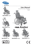
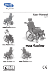
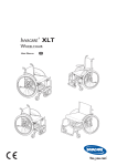
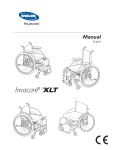
6.4 PROPELLING DOWN A SLOPE We recommend that you obtain the help of one or more assistants when going down steep and wet slopes. First check the slope to see if there are any particular hazards, potholes, slippery sections, etc. Never use the user-operated brake to slow down. When you apply the brake on a downward slope, the wheels lock and the wheelchair can suddenly pull to one side, tip sideways or stop immediately, which may cause you to be thrown out of the chair. Always control the speed with the hand rims. Remember that the hand rims may become hot due to friction, and this may cause injury to your hands. Try to propel down the slope in a straight line as much as possible. 6.5 CLIMBING A KERB This method is for when the assistant is always behind the wheelchair and it creates the greatest safety for the user. The following advice is for the assistant: Illustration 1) Adjust the anti-tip devices upwards. Ensure that the user’s feet rest securely on the footrests and cannot slide off. Then tilt the wheelchair backwards and push it forwards against the kerb. Illustration 2) Lower the frontal part of the wheelchair onto the pavement and place yourself as close to the chair as possible, before you lift up the whole wheelchair. Illustration 3) Lean forward and lift/roll the wheelchair over the pavement edge. Illustration 4) Lower the wheelchair onto the pavement so that the weight is divided on all four wheels. Ensure that the wheelchair does not roll backwards. To dismount kerb, follow the procedure above, but in reverse order (step 4, 3, 2 and then 1) to move off a kerb. Azalea R 39 6.6 KERBS – ALTERNATIVE METHOD 6.7 ESCALATORS AND STAIRS This method is generally used by experienced assistants who are stronger than average. It can also be used when the kerb or step is low and only constitutes a minimal obstacle. Do not use escalators when you are in the wheelchair. Find out whether there is a lift nearby. The assistant steps backwards onto the pavement and pulls the wheelchair up onto the pavement. It is important for the assistant to use his or her body correctly to prevent injury. Tip the wheelchair backwards and roll the chair over the kerb onto the pavement. Take particular care if the kerb is wet or slippery. 40 We recommend that you receive help from two assistants to get up and down stairs. One assistant walks in front of the chair holding the frame of the wheelchair, whilst the other assistant walks behind the chair, holding the push handles. Check that the push handles/push bar are securely fixed in place before you start. Fold the anti-tip devices upwards. Balance the wheelchair on the rear wheels until the balance point is found. The wheelchair is then rolled down the stairs, step by step, by letting the rear wheels roll over the edge of each step. Assistants must not lift by gripping the removable armrests or legrests. They must remember to lift the chair at the correct points, to use their legs and to keep their backs as straight as possible. Azalea R 7. Transport Invacare has continuously worked to improve the safety in all our products for the users in different everyday situations. This has, among other things, meant that Invacare since the mid 1990’s has let accredited research institutes crash test several of the manual wheelchair models.We would like to inform you about the transport of wheelchairs with seated users in vehicles that are especially adapted for this purpose. First and foremost, we would like to point out that it is always the safest option for the user to be transported in the vehicle’s regular seat fastened with the regular safety belt. Invacare cannot recommend transport seated in the wheelchair. But, we are aware that there are users and situations that require vehicle transport seated in the wheelchair. In these cases, the safety rules in this section must be followed in order to reduce the risk of injury in the case of an accident. The wheelchair has been tested according to the specifications in ISO 7176-19 “Wheeled mobility devices for use as seats in motor vehicles”.This means that it has been through and met the requirements in a standard test of one possible situation – full frontal collision in 48 km/h with a deceleration of 20 g and a 75 kg test dummy. The test standard ISO 7176-19 is developed by authorities and specialists and it states a minimum demand on wheelchairs regarding transport in vehicles. This standard is updated regularly as knowledge and experience increases. In reality, an incident will be different from the circumstances in a test laboratory environment. For example will speed, impact angle, configuration of the chair, user weight and deceleration probably vary. Invacare declines any responsibility for the outcome of a possible accident where our products are involved.We have chosen to test what we believe to be a frequently occurring configuration with common adjustments made. Configurations and accessories that are unsuitable for seated transport in a vehicle are mentioned later on in this chapter. 7.1 TRANSPORTING WHEELCHAIRS WITH USERS IN VEHICLES 1.The wheelchair and user should be transported forward-facing in the direction of travel. All auxiliary equipment such as tables, trunk support, abduction cushion etc should be removed and stored safely so that they do not injure anyone during any kind of accident. 2. The wheelchair should be secured in the vehicle with a 4-point restraint system. The user should wear a 3-point safety belt secured in the vehicle. Both the 4-point restraint system and the 3-point safety belt should be approved according to ISO10542-2. 3.The tie-down points on the wheelchair where the restraint system straps should be placed are marked with this symbol. Azalea R 41 Incorrect placement of safety belt 4. In order to be used as a seat during transport in a vehicle, the wheelchair must be equipped with a pelvic belt. 5. The vehicle's safety belt should fit as tightly across the user's body as possible without discomfort. The upper part of the safety belt should fit over the user's shoulder as illustrated. No part of the safety belt must be twisted. 7. The 3-point safety belt must not be held away from the user's body by parts of the wheelchair such as armrests or wheels etc. Incorrect Correct 8. A headrest should always be used during transport and it should be adjusted as shown in the picture. 6. The pelvic part of the 3-point safety belt must be worn low across the pelvis so that the angle of the pelvic belt is within the preferred zone (A) of 30° to 75° to the horizontal. A steeper angle is preferred, but never exceeding 75°. 42 Azalea R 7.2 RESTRAINT METHODS Frontal restraints with straps 1. Connect the frontal straps around the castor attachment. See pic A. 2. Release brakes and tension front straps by pulling the wheelchair backwards. Re-apply wheelchair brakes. Rear restraints 1. Attach the snap hooks on the rear straps to the vertical rear tube by the rear wheel attachment. 2. Tighten the straps. Fastening of pelvic belt and safety belt 1. Check that the pelvic belt on the wheelchair is correctly fastened. 2. Fasten the 3-point safety belt around the user. If there is no pelvic belt in on the wheelchair the user must transfer to the seat of the vehicle. The safety belt should not be kept from the user’s body by the parts of the wheelchair. Never use the harness and pelvic belt in a vehicle as a safety belt. A belt designed for transport in vehicles must always be used. Azalea R 43 7.3 HOW TO DISASSEMBLE YOUR AZALEA® TO TRANSPORT IT AS LUGGAGE The Rea® Azalea is easy to prepare for transport. E B A Backrest Remove the backrest cushion by pulling it forwards, thus separating the Velcro straps. Loosen both knobs (A) and pull the backrest directly upwards. On the Azalea Max, the pin (B) should be released. Lay the backrest on the seat, where it can remain during transport of the wheelchair. Where applicable, detach the push handles. Be careful with the cables that run from the rear wheel to the push handles. When detaching the backrest and placing it on the seat, try to make sure that the cables hang freely. Legrest fixed The footrests are loosened by pushing the handle (E) forwards or sidewards whilst turning the footrests outwards. You can then simply lift off the footrests. F C Armrests, Press the button (F) on the spring to release before removing the armrest. Push handles braced/push bar Loosen the two knobs (C). The height of the handles can be adjusted simply by pulling the handles upwards or pushing them downwards. D G Legrests angle adjustable The legrests are loosened by pushing the lever (D) forwards whilst turning the legrests outwards. You can then simply lift off the legrests. 44 Rear wheels Remove the rear wheels by pushing buttom (G) and pulling the wheel straight out. Azalea R Lifting the wheelchair Always lift the wheelchair by gripping the frame at the points shown in the diagram. Never lift the wheelchair by the removable armrests or the footrests. Azalea R 45 8. Maintenance 8.1 SAFETY INFORMATION Regular checks and maintenance of the wheelchair ensure the user’s safety and the expected lifetime of the chair. 8.2 MAINTENANCE SCHEDULE Check... Weekly Tyre pressure X QR axles rear wheels X All fasteners for wear and tightness Castors Anti-tip devices Chassis Upholstery Brakes Montly 6 months X X X X X X Tyre pressure Recommended air pressure for rear wheels: Standard tyres 3.5 bar 50 psi Low profile tyres 7.0 bar 90 psi Anti-tip devices Check that the anti-tip device is easy to adjust and fold. Chassis Recommended air pressure for castors: (200 mm) 8” 4.0 bar Check the chassis for wear and tear like loose parts, cracks or other defects. A damaged chassis should be checked by a specialist. Quick release axles rear wheels Upholstery Pull on the rear wheel to check that the removable axle does not come off. Check the upholstery for wear and tear like loose parts, rips or other defects. All fasteners (bolts) Bolts and other fastners ca come loose due to constant use. Check that the fasteners are tight on the castor forks, fottret, seat, side supports, backrest, handles etc. Tighten any loose bolts. Brakes Check that hub brakes work properly on both tyres. Check the positioning of the user brakes. Castors Check that the castors turn freely. Remove any dirt and hair. 46 Azalea R 8.3 CLEANING Wipe metal parts and the upholstery regularly with a damp cloth. A mild detergent may be used. If necessary, the upholstery can be washed at 40ºC. Normal washing powder/liquid may be used. For disinfection only use alcohol based detergent. Washing and Disinfection 1. Remove all loose and removable covers and wash these in a washing machine following the washing instructions for each article. 2. Spray the wheelchair with detergent, for example a car-cleaning agent with wax, and leave on to work. 3. Rinse the wheelchair with a high-pressure cleaning or ordinary jet of water depending on how dirty the chair is. Do not aim the jet towards bearings and draining holes. If the wheel chair is washed in a machine the water must not be hotter than 60 degrees. 4. Spray the chair with alcohol for disinfection. 5. Leave the chair to dry in a drying cabinet. Remove parts where water has collected for example in end tubes, ferrules etc. If the chair has been washed in a machine, blow-drying with compressed air is recommended. Azalea R 47 9. After use RECYCLING The wheelchair Rea® Azalea can be divided into the following main components: Chassis Plastic parts Upholstery Wheels, tyres and tube Packing Chassis The chassis is produced in steel and is fully recyclable. Recycling of steel requires only 20-25% of the energy compared to new produced steel. Rea® Azalea has two gas pistons and they contain oil and must be disposed according to national requirements. Be aware of that the gas pistons contains high pressure and must be handled with care during destruction. Plastic parts The plastic parts in the chairs are produced of “Thermoplastic” and are marked with recycling symbols (where it is possible due to part size). The main plastic material is polyamide. This material can be recycled or burned in approved facilities. Upholstery Upholstery is produced of polyester fibres (PUR). The efficient way to recycle the parts is to burn them in approved facilities. Wheels, tyres and tubes The handrim, rim, spokes and hub are made of steel, stainless steel or aluminium and can be recycled according to above. * Packing All Invacare Rea AB packing material is developed to fit the products in an optimal way to reduce unnecessary material waste. All boxes are recyclable. Contact your local recycling agent to otain the correct information on how to handle the above mentioned materials. 48 Azalea R Notes Azalea R 49 Manufacturer Invacare Rea AB Box 200 SE-343 75 Diö SWEDEN Sales Companies Denmark: Invacare A/S, Sdr. Ringvej 37, DK-2605 Brøndby Tel: (45) (0)36 90 00 00, Fax: (45) (0)36 90 00 01 [email protected] / www.invacare.dk Deutschland: Invacare GmbH, Alemannenstraße 10, D-88316 Isny Tel: (49) (0)75 62 7 00 0, Fax: (49) (0)75 62 7 00 66 [email protected] / www.invacare.de Ulrich Alber GmbH, Vor dem Weissen Stein 21, D-72461 Albstadt-Tailfingen Tel: (49) (0)7432 2006 0, Fax: (49) (0)7432 2006 299 [email protected] European Distributor Organisation: Invacare, Kleiststraße 49, D-32457 Porta Westfalica Tel: (49) (0)57 31 754 540, Fax: (49) (0)57 31 754 541 [email protected] / www.invacare.eu.com España: Invacare SA, c/Areny s/n, Polígon Industrial de Celrà, E-17460 Celrà (Girona) Tel: (34) (0)972 49 32 00, Fax: (34) (0)972 49 32 20 [email protected] / www.invacare.es France: Invacare Poirier SAS, Route de St Roch, F-37230 Fondettes Tel: (33) (0)2 47 62 64 66, Fax: (33) (0)2 47 42 12 24 [email protected] / www.invacare.fr Ireland: Invacare Ireland Ltd, Unit 5 Seatown Business Campus, Seatown Road, Swords, County Dublin - Ireland Tel: (353) 1 810 7084, Fax: (353) 1 810 7085 [email protected] / www.invacare.ie Italia: Invacare Mecc San s.r.l., Via dei Pini 62, I-36016 Thiene (VI) Tel: (39) 0445 38 00 59, Fax: (39) 0445 38 00 34 [email protected] / www.invacare.it Nederland: Invacare BV, Celsiusstraat 46, NL-6716 BZ Ede Tel: (31) (0)318 695 757, Fax: (31) (0)318 695 758 [email protected] / www.invacare.nl [email protected] Norge: Invacare AS, Grensesvingen 9, Postboks 6230, Etterstad, N-0603 Oslo Tel: (47) (0)22 57 95 00, Fax: (47) (0)22 57 95 01 [email protected] / www.invacare.no [email protected] Österreich: Invacare Austria GmbH, Herzog Odilostrasse 101, A-5310 Mondsee Tel: (43) 6232 5535 0, Fax: (43) 6232 5535 4 [email protected] / www. invacare.at Portugal: Invacare Lda, Rua Estrada Velha, 949, P-4465-784 Leça do Balio Tel: (351) (0)225 1059 46/47, Fax: (351) (0)225 1057 39 [email protected] / www.invacare.pt Sverige & Suomi: Invacare AB, Fagerstagatan 9, S-163 91 Spånga Tel: (46) (0)8 761 70 90, Fax: (46) (0)8 761 81 08 [email protected] / www.invacare.se [email protected] Switzerland: Invacare AG, Benkenstrasse 260, CH-4108 Witterswil Tel: (41) (0)61 487 70 80, Fax: (41) (0)61 487 70 81 [email protected] / www.invacare.ch United Kingdom: Invacare Limited, Pencoed Technology Park, Pencoed, Bridgend CF35 5AQ Switchboard Tel: (44) (0)1656 776200, Fax: (44) (0)1656 776201 Customer services Tel: (44) (0)1656 776222, Fax: (44) (0)1656 776220 [email protected] / www.invacare.co.uk Art.no. 1488727-11 2011-04-03 Belgium & Luxemburg: Invacare nv, Autobaan 22, B-8210 Loppem Tel: (32) (0)50 83 10 10, Fax: (32) (0)50 83 10 11 [email protected] / www.invacare.be