1
SOFTWARE GSPARALW - Version C
USER MANUAL
Georges STEVENS
6 Impasse d’Ossau 64140 LONS - France
Tél. et Fax (33) 5 59 32 29 65
27-03-2006
QUICK INSTALLATION
AND SURVEY
Installation
Insert the CD in its drive. If its contentsdo not self display, open it with Windows Explorer.
To install GSPARALW on yoru hard disc, double-click on the installation programme
InstalParal\il. It will createa folder named GSRBPER (if not yet existing) and will copy in
and
it the software. It will also copy six auxiliary files named ParalWDl...4.dtt
ParalWNl.. .Z.dat containing the tolerancesper NF E and DIN. In addition, it will createa
short cut and its icon on your computer desklop ; you will just have to double click on the
icon to run GSPARALW.
If sonvenient,the file gsparalw.exe can be moved manually anywhereon your hard disc.
Suruev
The organigram of GSPARALW is visible from all pages(except Help pages)by clicking on
the red button O located in the upper left corner. From it you can see where you are in the
software and where to go.
Help in line is available when necessaryby clicking on menu Help. In addition, some datum
fields provide a specific help ; when passingover them with the cursor, the mention "F I :
Help" is displayed.Focusnow the field by clicking on it and presskey Fl.
1
IMPORTANT
17-11-2006
This software cannot be transferred or copied to the benefit of any other company or people without the Author’s
permission. Its use is subject to your acceptance of the conditions accessible from the first page of the software.
FOREWORD
GSPARALW Version C is an efficient software to deal with all the problems involved in parallel gearing, spur
or helical, external or internal, including simple epicyclic trains.
It allows quick and accurate determination of the following dimensions :
- reference and operating pitch diameters, tip and root diameters, base diameters and helix angle.
- minimum operating radius when engaged with another element.
- transverse contact and overlap axial ratios.
- span dimensions and dimensions over pins .
- tolerances as per french standard NFE 23-006, german standard DIN 3062 and ISO 1328-1 and 2.
In addition it :
- advises all kinds of interference or undercutting.
- allows automatic determination of optimum basic rack shift coefficients to prevent undercutting and exactly
balance the slide-roll ratios of pinion and wheel.
- checks the full suitability of a shaper to cut an internal wheel.
- draws and prints the section of the pinion and wheel tooth.
- calculates the bearing loads.
- determines the cutting times.
- allows to visualize the meshing cycle.
Help in line is available whenever possible and necessary. Click on Menu Help or button ?. In addition, a
specific help in line is available for certain capture fields. These fields are advised by a bubble F1=Help
displayed when the cursor passes over the field. Click on the field to focus it and press key F1. On the DATA
page, the menu Help gives access to an option allowing a predetermination of the numbers of teeth and module
for a given torque to be transmitted.
When a gear or a pair of gears has been designed, GSPARALW allows recording on disc of all dimensions and
tolerances for a future recall.
With the extension LOAD CAPACITY it determines the torque and power capacity according to :
- NFE 23-015 french standard.
- AGMA 2001-B88 american standard of September1989. With possible application of the Miner’rule for
variable loadings.
- ISO 6336.
- method of G. HENRIOT proposed in his book TRAITE THEORIQUE ET PRATIQUE DES ENGRENAGES.
2
GSPARALW makes them easily accessible to engineers who are not specialized in gearing and will certainly
prove helpful even to specialists
LIMITS
GSPARALW is suitable only for involute parallel axis gears, either spur or helical and spur internal. Low tooth
external gears as STUB are accepted.
RUNNING GSPARALW
GSPARALW is protected by two codes, the first one referring to the dimensional section, the second one to the
extension LOAD CAPACITY
If you are in a trial period and therefore do not know the codes, you however can have access to all functions and
options of GSPARALW, including the extension LOAD CAPACITY, but only odd number of teeth will be
accepted.
When numbers in parenthesis are displayed, they refer to the corresponding paragraphs ( ) of this manual.
After having choosen either conventionnal gears or epicyclic train a first menu is displayed with the following
options :
- a new case : to be selected to deal with a new problem. Recording will be possible for later recall.
- read ... from disc with modifications : allows reading of a previously recorded case with possible
modification of data.
- read ... from disc without modifications : allows reading of a previously recorded case without modification
of data.
- replace worn out gears : to determine the dimensions to be given to gears to replace existing worn out.
- delete ... on disc : to delete an element or train previously recorded. If the element to be deleted has been
recorded with a mating element, both will be deleted.
- save the file ... .dat : it is recommended to save periodically the files PARGEARW dat and PLANETW.dat
containing the records. If necessary it will be then possible to reload the records from the disquette to the
directory GSREPER.
- exit GSPARALW : if a case has been dealt with, GSPARALW will ask if you wish to record it before leaving.
In case of option 1, you will have to choose between one external or internal gear, or two external or internal
gears.
In case of options 1 and 2, GSPARALW displays an editing page. Select first the type of gear(s), then the
desired options, then fill the other fields. With Stub teeth the options “Manual rack shift” and “Free centre
distance” are only accessible.
Each element can be identfied by a reference (30 characters), a number (8 characters) and an index. These
identications will be used for a later recall.
RECORDING ON DISC
Each time a new case has been dealt with, or when an existing case has been modified, GSPARALW will ask if
you wish to record for a later use.
When the case dealt with comprises two elements, pinion and wheel, each one is recorded under its own
identificators but when one of them is later recalled its mating element is also read. If you omitted the reference
and number, they will be asked for before recording. If you just have modified an existing case, it will be
recorded under the former reference and number.
3
READING FROM DISC
In case of options 2, 3 and 5, GSPARALW displays a selecting grid.
Sorting is carried out either with alphabetic references, or increasing numbers, or increasing modules.
On each line can be seen the reference, the number, the index if any, the normal module, the number of teeth
followed by the letter I if internal gear, the helix angle followed by the letter R or L according to the helix hand,
the number of teeth of the mating gear if any followed by the letter I when internal or rack if a rack.
When the record comprises two elements, both are read.
DIMENSIONAL SECTION
DATA SYMBOLES AND UNITS
All dimensions in mm unless otherwise specified, loads in Newton, torques in N.m, powers in kW and angles in
decimal degrees.
Subscript 1 refers to pinion, subscript 2 to wheel and subscript 0 to tool.
Aw
centre distance at zero backlash. When the algebraic sum (external gears) or difference
(internal gears) of the basic rack shift coefficients is not zero, it is taken into account. When
the pinion is associated to a rack, aw is the distance from the pinion centre to the rack reference
line.
b
face width.
d
reference pitch diameter.
da
tip diameter. When the sum (external gears) of the basic rack shift coefficients is not zero, this
dimension may be slightly reduced to maintain the bottom clearance. It may similarly be
slightly increased with internal gears to prevent interference.
db
base diameter.
dw
operating pitch diameter.
F1,2,3,4
load on bearing 1,2,3,4. See Help in line.
K
number of teeth for span gauging.
L1,2,3,4
distance from centre plane to bearing 1,2,3,4. Help in line.
mn
normal module.
rt0
tip radius coefficient of cutting tool. See Help in line.
sna
normal crest thickness. When the data entered lead to a value smaller than 0,3 mn, it is
advised. When they lead to a negative value (sharp crest), it is rejected. See later.
W
span gauging over K teeth.
x
basic rack shift coefficient. It is positive when the basic rack reference line does not
intersect the reference pitch circle diameter, negative when it does. This definition is
applicable to both external and internal gears.
y0
tool addendum coefficient. See Help in line.
4
alphan
normal pressure angle.
beta
helix angle.
betab
base helix angle.
delta 1,2,3,4
angle of load F1,2,3,4. See Help in line
epsilon alpha
transverse contact ratio.
(1)
epsilon beta
overlap axial ratio. Should be > 1 to provide full advantage of helical gearing. When
epsilon beta < 1 the load capacity of helical gears is impaired. Increase helix angle or face
width or choose a smaller module to make epsilon beta > 1.
(2) AUTOMATIC DETERMINATION OF RACK SHIFT COEFFICIENTS
The option "automatic determination of rack shift coefficients" not only prevents undercutting but optimises the
rack shift coefficients to balance exactly the slide-roll ratios of pinion and wheel.
(3) This option is accessible as well with free or imposed centre distance, for external or internal gears. For the
latter it is however quite satisfactory to give both pinion and wheel a positive coefficient of 0.4 to 0.5 normal
module.
Incidentally the slide-roll ratio, the value of which is displayed, characterises the resistance to wear : the closer it
is to zero, the closer the contact is to pure rolling and therefore the smaller is the wear. The balance results in an
equal sharing of wear between pinion and wheel.
EXTERNAL GEARING
(4) When the data entered, number of teeth, helix angle, rack shift coefficient lead to undercutting with rack
cutter or hob, it is advised. It is then possible either to continue with undercutting, or to go back to modify one or
more parameter(s) and cancel undercutting. Clearly this last option is strongly recommended. If however
undercutting is accepted, it is suggested to draw the tooth section to appreciate its amount.
(5) When the data entered lead to a tip thickness smaller than 0.3 mn, it is advised. This value is normally a
minimum especially with case hardened gears.
(6) When the data entered lead to a negative tip thickness (sharp crest) it is rejected.
INTERNAL GEARS
Internal gears are subject to specific restrictions or interferences examined below.
Limitation of tip diameter da2
When the flank of the mating pinion is generated by a rack or hob, the involute profile extends downward to a
definite radius depending on the rack shift coefficient, the tool addendum and the tool tip radius. But if the wheel
tooth total height is held normal (2 normal module), it may require that the arc of involute of the pinion tooth
flank extends lower than actually generated. In this case, GSPARALW automatically increases da2 by a small
amount just preventing the interference.
In the case of a shaper, GSPARALW gives the radius to which the arc of involute should extend to generate the
wheel profile down to its tip.
5
All these calculations are carried on from nominal dimensions. When some backlash is provided by the wheel,
the shaper is fed slightly deeper. The result is a slight easing at the wheel tooth tip which is negligible and does
not affect the wheel behaviour.
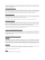
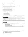
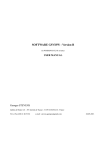
(7) Trochoïdal interference (Fig. 1
When the difference between the pinion and wheel numbers of teeth is too small, this specific interference may
occur. In this case the pinion (or shaper) tooth tip trims the wheel tooth tip. This type of interference is advised
and the amount of trimming is given as well for the pinion as for the shaper. With a pressure angle of 20° a difference of 8 teeth between pinion (or shaper) and wheel is usually sufficient to prevent interference.
(8) Radial engagement (Fig. 1
When the difference between the pinion and wheel numbers of teeth is not sufficient, it may not be possible to
engage the pinion radially in the wheel, but only axially. In the case of a shaper it is clearly impossible to make
axial engagement and consequently trimming of the teeth would result..
This is advised as well for the pinion as for the shaper. In this latter case the amount of trimming is given.
(9) Interference at tooth bottom
When the shaper addendum is not sufficient to generate the wheel profile to the necessary height, an interference
may occur when meshing with the pinion. This is exactly the same type of interference as that existing at the tip,
but now at the bottom. GSPARALW advises this type of interference. Another shaper can then be selected or,
alternatively, reduce the pinion tip diameter by an amount equal to two times the interference.
All these calculations are carried on from the nominal dimensions. If some backlash is provided by the wheel,
the shaper is engaged slightly deeper and some safety margin will result.
ALLOWANCE ON SPAN DIMENSIONS W/K TEETH
Allowances on dimension W/K teeth controling the backlash are entered on the editing form. If preferred they
can alternatively be entered from the form tolerance NFE 23-006. The corresponding dimensions over rollers are
displayed. Note that negative allowances provide backlash with external gears but positive allowances are
required with internal gears.
(10) DRAWING OF NORMAL TOOTH SECTION
External gears
GSPARALW draws the section in a normal plane as generated by a rack or hob. The fillet shape is true and it is
possible to appreciate the effect of undercutting. For helical gears, the section is that of the spur gear having the
virtual equivalent number of teeth. Errors involved are negligible and always smaller than the screen resolution.
Drawing and printing of several teeth are available only with spur gears. For helical gears indeed it would be
necessary to draw the transverse section which would not be representative of the form and resistance to failure.
Internal gearing
GSPARALW draws only the arc of involute : the fillet is not drawn since widely depending on the shaper data. It
is in addition of no interest since the bending strength of an internal wheel is never critical.
In both cases the reference pitch circle is drawn.
Printing
Enter the enlargement factor (scale) of printed tooth.
6
MESHING CYCLE
This option draws the surface of contact and the teeth in the transverse plane. The teeth can be moved within a
cycle to examine the meshing. All necessary informations are given through the “Help in line”.
BEARING LOADS
Distances L1, 2, 3, 4 are measured from centre plane of gear to bearing 1, 2, 3 or 4. See Help in line.
(11) It is important to enter these distances as positive or negative in accordance with the figures obtained with
the Help in line. Bearings below the centre plane of gears involve negative values of L. The direction of rotation
and helix hand applie to the pinion. When the wheel is driving (speed increaser), reverse the direction of rotation.
GSPARALW displays for each direction of rotation and helix hand the load applied to each bearing for a unity
torque at the pinion. Multiply the figures displayed by the actual torque to obtain the actual load.
GSPARALW also displays the load angle (dec. degrees) for each bearing as measured from the centre line.
(12) Tolerances NFE 23-006
Tolerances according to the french standard are easily accessible as well for the pinion as for the wheel.
Allowances can be applied either to the span dimensions W/K teeth or to the tooth normal thickness. Some
comments follows.
Most standard allowances are negative in order to provide backlash. If they were applied to the span dimensions
W/K teeth of internal gears the result would be seizure instead of backlash. This is why the application to the
span dimensions is possible only with external gears. If the application is selected to the circular thickness,
backlash is obtained as well with external as internal gears.
It will be noticed that when the application is selected to the thickness, the allowances have not the same values
on the form “tolerances” or “dimensions”. This is because in the former case they apply to the thickness while in
the latter they apply to the span dimensions and are therefore multiplied by the cosine of the normal pressure
angle. For the same reason, the signs are different in the case of internal gears ; a reduction of the thickness
results in an increase of the span dimensions.
(13) Tolerances DIN 3962 (August 1978)
Tolerances according to the german standard are easily accessible as well for the pinion as for the wheel.
Translation of the german terms are given hereunder without any liability.
Profil-Formabweichung ff : profile shape error
Profil-Winkelabweichung fHalpha : profile angle error
Profil-Gesamtabweichung Ff : profile total error
Teilungs-Einzelabweichung fp : individual pitch error
Eingriffsteilungs-Abweichung fpe : gear pitch error
Teilungssprung fu : pitch error
Teilungs-Gesamtabweichung Fp : pitch total error
Teilungs-Spannenabweichung über 1/8 Umfang Fpz/8 : pitch error on 1/8 revolution
7
Rundlaufabweichung Fr : radial runout error
Zahndickenschwankung Rs : allowance on tooth thickness
Flankenlinien-Gesamtabweichung Fbeta : flank line (helix) error
Flankenlinien-Winkelabweichung FHbeta : flank line (helix) angle error
Flankenlinien-Formabweichung Fbetaf : flank line (helix) shape error
Teilungs-Spannenabweichung Fpk : pitch error over N teeth
ISO Tolerances ISO 1328-1 and 2
Tolerances according to ISO are easily accessible as well for the pinion as for the wheel.
(14) IMPORTANT : Values displayed are those found in the standard issued by the french Association Française de normalisation (AFNOR) under reference E 23-007-1 et 2. However this document incorporates two
mistakes :
1°/ Total pitch error Fp for 1600 <dia.<=2500, 40<mod.<=70, precision class 11.
The (wrong) value given by the standard is 603 when the correct value is 630.
2°/ Total profile error Falpha for 6000<dia.<=8000, 16<mod.<=25, precision class 9.
The (wrong) value given by the standard is 113 when the correct value is 133.
GSPARALW displays the correct values, not those given by the french edition.
GSPARALW displays the cumulative pitch tolerance for all teeth and for half the circle. Normally it is however
checked on only 1/8 of the total number of teeth.
EPICYCLIC TRAINS
Details to use this option are accessible on line by clicking on menu Help or when existing on icon ?.
Following are some comments regarding this type of gearing.
Ratio of train It is equal to
Number of teeth in crown
------------------------------------ + 1
Number of teeth in sun
with the sun driving and the crown fixed.
Number of teeth The numbers of teeth in sun and crown, which determine the train ratio, are normally entered.
The normal corresponding number of teeth in planets is automatically displayed. When necessary, for example to
cure undercutting, it can be reduced or increased by one unit. In order to ensure equidistant location of planets,
the sum (number of teeth in sun + number of teeth in crown) divided by the number of planets must be an
integer. If the entered numbers of teeth do not comply with this rule they are refused.
Automatic basic rack shift When this option is selected, the sun and planets rack shifts are optimised by
equalling their slide-roll ratios. The crown rack shift is then determined from the planet one. The sun planet
meshing is preferred because the load capacity of the planet crown meshing is normally largely in excess of the
other one.
Recording The train data are saved separately from those of conventionnal gears in a file named PlanetW.dat
located in the directory named GSREPER.
8
EXTENSION "LOAD CAPACITY"
Epicyclic trains
The displayed load capacities take in account the total number of planets. It is assumed that the load is perfectly
shared by the planets, this of course being never achieved. It is the responsibility of the designer to reduce the
values displayed in accordance with the actual degree of misbalance, having in mind that a satisfactory sharing
can be obtained with 2 and still more 3 planets but that with more planets the sharing can be only very poor.
The calculations are based on the relative speeds of the elements. All indeed behave as if the planet carrier was
fixed and the sun speed being that relative to the sun carrier. This relative speed is equal to
1
Nrelative = N (1 - -----)
K
where K is the train ratio as determined above.
Account is of course taken of the sun and crown number of meshings multiplied by the number of planets, and of
the number of planet meshings multiplied by 2.
The four methods proposed for the evaluation of the torque and power capacity of parallel axis gears are applicable either to internal (except NFE 23-006) or external, spur or helical, with involute profile.
The gear capacity is limited either by surface stress (pitting resistance or wear) or bending stress (bending
strength). The load capacity of a pair of gears should therefore be determined using four calculations, for pitting
and for bending of both pinion and wheel.
These four methods do not allow calculation of bending strength of internal gears since this type of gear is
normally not subject to this kind of bending failure.
GSPARALW allows easy determination in a few seconds of the corresponding ratings with however the following limitations :
- the working height of the tooth must be 2 normal modules. Low tooth such as STUB are not allowed.
- the profile must be involute without transverse or axial modification such as crowning or tip easing or
semi-topping.
- the profile must be free of any kind of undercutting or interference.
- no service factor is taken into account. The designer should therefore appreciate and apply it to the results.
DATA SYMBOLS AND UNITS
Unless otherwise specified all dimensions are in mm, loads in Newton, torques in N.m and powers in kW.
Subscript 1 refers to pinion, 2 to wheel.
b
face width of the narrowest element.
E
modulus of elasticity (N/mm²). See Help in line.
HB
Brinell hardness (ball dia. 10 - 3000 Kg). See Help in line.
M1
allowable pinion torque.
n1
pinion speed (r.p.m.).
P
power.
z2c
operating number of teeth in rack. When variable enter an average number.(15).
9
Life :
it is the value (hours) which can be reasonnably expected. Because of the unavoidable
dispersion in manufacture it should not be considered as absolutely certain but as a reasonnable
figure to be expected. Since a global life figure has been entered it is not necessary to enter a
daily working time ; there is indeed no difference between ten years at 12 hours/day and five
years at 24 hours/day.
(16)
Shared torque : when one single pinion drives two wheels.
(17)
Intermediate wheel : idler or jockey wheel. It is free on its shaft, is driven by a pinion and
drives another pinion or wheel.
METHOD NFE 23-015
This method is the french proposal to ISO/TC. The simplified method as found at the end of the standard is used
here.
It is not aplicable to internal gearing.
ISO quality number should be from 5 to 8.
(18) It introduces a reliability factor for application where more failures are accepted, or conversely when high
reliability is required. The number Fi to be entered corresponds to a failure probability of 1/Fi. For example if
Fi = 100 is entered (as it is in usual commercial applications), 1 failure out of 100 is to be expected.
It is a modern method well suited to commercial applications as usually encountered.
Datas and symbols
sigmaF
basic stress factor for strength (N/mm²). See Help in line.
sigmaH
basic stress factor for pitting (N/mm²). See Help in line.
NM
material number. See Help in line.
ISO
quality number from 5 to 8.
METHOD AGMA 2001-B88
It is probably the most advanced but however the most difficult to use. The new standard 2001 B88 has superseded the former standard 218.01.
The new standard provides a considerably wider range of values for Sac and Sat vs the material physical data
(some 15 pages). In order to simplify the selection the old tables of 218.01 have been retained in this leaflet :
their values for Sac-Sat are indeed a little more conservative and quite sufficient for commercial applications.
Clearly the new standard can be referred to when necessary or wished.
The determination of the load distribution factors Cm-Km is difficult when using the analytical method : it is
indeed uneasy to appreciate a true value for the lead mismatch et. The alternative empirical method is easier to
handle and has therefore been introduced.
Both external and internal gears can be dealt with and a reliability factor can be introduced.
IMPORTANT : the AGMA quality number to be entered is not the same as the ISO one but is specified in
AGMA 390. There is no strict correspondance between the ISO and AGMA systems, however an approximate
equivalence can be found on Help in line.
The load distribution factors Km-Cm can be determined from the methods described in the standard. Some
comments and explanations are given below.
10
(19) Empirical method (to be preferred when possible)
The following conditions are required :
- face width should be smaller than or equal to 2 x pinion reference pitch diameter.
- both elements should lie between the bearings (no overhanging).
- maximum face width 1016 mm (40").
- the contact under load must spread over the full face width.
Dimensions S1 and S are shown on Help in line.
Applications are to be classified in four categories :
- open gearing.
- commercial enclosed gear units.
- precision enclosed gear units.
- extra precision enclosed gear units.
AGMA does not give any further information or comment regarding these categories but clearly the usual
commercial applications are to be classified in the second one.
(20) Analytical method
Due to unavoidable errors in elements assembly and leads (distorsion) the light load contact is punctual. Under
load the contact spreads over as a line and should normally spread over the whole face width. GSPARALW
advises when it does not and displays the ratio Fm/b where Fm is the actual loaded width of contact. The ratio
Fm/b depends basically on the value of mismatch et explained below.
When calculating the strength capacity the tooth thickness reduction to provide the necessary backlash is taken
in account.
Datas and symbols
et
total lead mismatch between mating teeth. It represents the combined effects of the influences listed
below except hertzian contact and bending deformation at the tooth surface :
- errors of lead in machining.
- errors in the alignment of the shafts.
- elastic deflections of mounting elements under load such as shafts, bearings, housings, foundations
etc.
- bearing clearances.
- thermal expansion.
- centrifugal forces.
The value of et is very difficult to estimate and require very careful consideration : the calculated load capacity
depends indeed widely on it. It therefore requires all the designer wisdom and experience.
Fm
loaded width of contact. See above.
11
Qv
AGMA quality number. Does not correspond to ISO quality number. See Help in line.
Sac
allowable contact stress for pitting (N/mm²). See Help in line.
Sat
allowable bending stress (N/mm²). See Help in line.
(22) Load sharing : accurate spur gears develop the most critical stress when the load is applied at the highest
point of the tooth when a single pair of teeth is carrying all the load. Less accurate spur gears having errors that
prevent two pairs of teeth from sharing the load may be most heavily stressed when the load is applied at the tip.
See Help in line. This question is omitted with helical gears with overlap ratio > 1.
Miner’s rule
The Miner’s rule, although being not a part of the american standard AGMA 2001-B88, is however described
and recommended in its appendix B. It provides an efficient way to determine the expectable life of a pinion and
wheel set loaded by a repeated or single cycle incorporating several periods each of them of different torque
and/or speed, including uniformly variable torque and/or speed.
This option is only applicable in conjunction with the AGMA 2001-B88 method. More details and instructions
are given by clicking on Help of the corresponding form.
METHOD HENRIOT
It is very popular in France owing to the notoriety of its author.
It is very similar to NFE 23-015 although somewhat simplified. It is however quite reliable in most cases as
usually encountered.
It allows treatment of both external and internal gears but does not introduce a reliability factor.
Datas and symbols
ISO quality number : 5 through 12.
sigmaH allowable surface stress (N/mm²). See Help in line.
sigmab allowable bending stress (N/mm²). See Help in line.
METHOD ISO 6336 - D
The standard ISO 6336 proposes four different versions of its method denoted from A to D, the first one being
the most sophisticated but however the most difficult to use. The simplified version D is used here, sufficient for
usual commercial applications.
More details and instructions can be obtained from the Help in line.
Intermediate factors.
The main intermediate factors used in the calculataions can be displayed for the four standards and a calculation
sheet can be printed.
---------------
I
I
I
I
t-i g . '1.
INTEHNAL GEARS
'iÏJTTNR :TR]I.{MING
TROTHO]DAL TNTT]RF'ITREN
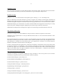
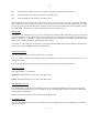
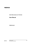
fiE ANTT
Spin Herdening
lnrluctionCoil
or FlameHcad
lnduction Coil
or Flamc Hcad
I
.
TVP'B
rlPe A
Ffrnk Herdening
Inductor or Flame Hcad
Inductor or Flame Hcad
ïype B
FbnL rnd Root llerdming
Inductor or Flamc Head
ffizn
tw
îVpc A
F ' i e" +
(
INDLIC'TT()N
{)R FIAT,IE HARDENTN{;