1
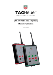
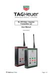
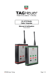
HL 670 Data / Impulse
Transmitter set
User Manual
Version 07/2010
1. Global
The Set HL670 is ideal for transferring Timing Data and Impulses.
Its 500mW emitting power and its licence free frequency range (869 Mhz) makes this
device a powerful and simple to use system.
Data / Impulse transmission system (500 Mw) which does not require a licence (free
of use) in Europe (ISM Band 869 MHz – REC 70-03).
Each Receiver can receive Impulses (simultaneously or not) from 4 Transmitters
identified by the function "CHANNEL" (1 to 4).
Up to 4 Teams can work (train) in the same area without disturbing each other thanks
to the function "TEAM" which offers the possibility to code each system
(A, B, C, D).
It is also possible to use up to 16 transmitters with 4 receivers.
When the receiver is switched on, it is possible that one or more green LED’s are on
before that the transmitter(s) start to transmit. This detection system allows
visualization of the quality of the received signal, but also the possible interferences
coming from other radio transmission systems. If it is not possible to stop these
interferences by moving the receiver, the transmission of Impulse cannot be
guaranteed.
Important Remark
Don’t forget to register your product online at:
http://www.tagheuer-timing.com/tools/product-register
1. Functions
The Transmitter :
9
10
6
7
5
8
2
4
1
3
11
1.
IMPULSE
Input for timing Impulse (Start gate, photocell – working / closing contact). Respect the polarities.
2.
DATA
Male Sub-D 9: RS232 input for DATA transfer
3.
POWER
To switch on the receiver (press for 3 seconds on POWER). The green LED is on.
To switch off the receiver, hold down SET and press POWER.
4.
SET
To program the TEAM (A, B, C, D) and to switch off the receiver. Hold down SET during the changes.
5.
TEAM
To check the programmed TEAM.
To change the code, hold down SET and press TEAM.
6.
CHANNEL
To check the programmed CHANNEL.
To change the CHANNEL, hold down SET and press CHANNEL.
7.
TEST
For testing the Impulse transmission only. The reception level will be displayed for 0.2 seconds on the
receiver. You’ll also get an Impulse on the programmed output.
8.
TEST BATT
To check the state of the battery. Press TEST BATT : The Battery level will be displayed with the 4 LED’s
for 2 seconds.
9.
LED
LED control panel which shows the programmed TEAM or CHANNEL. Also shows the transmitted Impulse.
10.
LED
Shows the transmission mode : IMPULSE or DATA
11.
CHARGE
Charging status Leds. The red led indicates that the Accu is charging. The charge is completed as soon as
the green LED in on.
The Receiver
9
7
6
8
5
10
2
1
4
3
1. IMPULSE
Output for timing Impulse (Start gate, photocell – working / closing contact). Respect the polarities.
2. DATA
Female Sub-D 9 : RS232 Output
3. POWER
To switch on the receiver (press for 3 seconds on POWER). The green LED is on. To switch off the
receiver, hold down SET and press POWER.
4. SET
To program the TEAM (A, B, C, D) and to switch off the receiver. Hold down SET during the changes.
5. TEAM
To check the programmed TEAM. The green LED corresponding to the code A, B, C or D is on. To change
the code, hold down SET and press TEAM.
6. LED
LED control panel which shows the programmed TEAM or CHANNEL. Also shows the Received Impulse.
7. LED
Shows the transmission mode : IMPULSE or DATA
8. LED
LED control panel which shows the Receiving Level and/or possible interferences created by other radio
signals.
9. BUZZER
To enable or disable the Buzzer
10. TEST BATT
To check the Battery status. The Level will be displayed with the 4 LED’s for 4 seconds:
4 LED’s on
= 80-100%
3 LED’s on
= 60-80%
2 LED’s on
= 40-60%
1 LED on
= 20-40%
1 LED on
= 0-20% power remaining
2. Battery Charging
Each device has a Lithium-Polymer battery with supply 2100 mAh. Those batteries
may be charged with our charger HL540-10 or other 12V charger with a minimum of
800 mA.
For charging the battery we advise you to use our OEM TAG Heuer charger
Using another model may cause some trouble or harm the device.
For charging, turn off the system.
Connect the charger on the mains
Plug the charger into the device
The red LED will be on during the charge
IMPORTANT :
Always charge the devices by temperature above 32°F (0°C) and below
86°F (30°C)
The red LED lights during the charging process, when fully charged, the red LED
shuts down and the green LED will light on.
For a fully charged Battery it may take approx. 5 hours (for a completely discharged
battery)
Never connect the terminals of the battery in short-circuit.
To avoid keeping the battery pack fully loaded or completely discharged for a long
period, which reduces the lifespan of the battery. In the case of prolonged nonutilization of the battery pack, it is necessary keep the system in a dry room, after
a normal discharge
In case of a reduced capacity of the battery pack, even after the load, leave the
system ON a whole night to obtain a complete discharge, then recharge the
battery pack completely.
Renew the battery pack if the problem continues.
3. System utility : TAG Heuer HL670 Configuration
Connect your device with the HL605-10 (delivered with the set) to your computer, run
the application. Turn on the system after pressing “Connect”.
This application is a free download from our Website : www.tagheuer-timing.com, It
enables you to configure the radio in different Baudrates:
2400, 9600 (Set by default), 38400, 57600,
115200 and 9600 bps with Flow control.
4. Software Update
With the Firmware (already used with the Chronoprinter 540 and the Minitimer HL440)
able you to change the transmission mode and Update your device.
For this application you need :
• The RS232 cable (HL605-10)
• A computer fitted with a D-Sub9 RS232 Output
• The software « Firmware.exe »
How to proceed
1. With the radio switched « OFF » connect the external power Connect the RS232
between your computer and the HL670
2. Run «Firmware.exe »
3. Select the correct COM Port
4. Browse and select the correct file (Rx/Tx)
5. Push START on the screen
6. Turn on the HL670 (hold down for 5 seconds « ON »
The HL670 will enter in a special setup mode
7. Until the file downloaded then, validate with « OK »
For each device, transmitter or receiver, two Software options are available :
o TAG Heuer Software (TH_Tx_Vxx / TH_Rx_Vxx)
This software is especially dedicated for the standard CP540 protocol and the
Minitimer. The 9600 with flow control Baud rate ensure that the frames are
correctly transmitted.
o Chronelec Software (or transparent mode) (THbC_Tx_Vxx / THbC_Rx_Vxx)
This mode is especially for devices which need a data transmission with different
frame length. The data transfer is made until the device receives a blank
message within 50ms with a maximum frame length of 127 characters.
The transmission for 43 octets (standard CP540 frame) takes 125ms with 9600 bps.
The timeline is composed
-
35ms for the RF transmission. This time does not depend on the baud rate just
on the number of octets.
45ms for sending the frame
45ms for receiving the frame on the receiver
We can reduce this transmission time by increasing the baud rate from the receiver
and/or the transmitter. For example, the same frame length with 115200 bps (on both
sides) will only take 42ms.
Those devices may be used in a “Relay” configuration by plugging directly the
Receiver on another Transmitter (through the banana socket or RS232 connection).
Hands on: Reinitialize your devices
If the systems are in a unknown mode, you can Initialise your system in the
OEM configuration (Channel 1, Team A, Buzzer On, Baud Speed
9600bps, Mode Impulse). Push simultaneously SET and TEST BATT for 3
seconds. All LED’s will flash and the system will beep until it is reinitialized.
5. Pinout
Transmitter (male socket)
Receiver (female socket)
1 NC
2 Radio RxD (RS232)
3 Radio TxD (RS232)
4 RS485 Signal B
5 GND
6 NC
7 RS485 Signal A
8 NC
9 NC
1 RS485 Signal A
2 Radio TxD (RS232)
3 Radio RxD (RS232)
4 NC
5 GND
6 NC
7 NC
8 NC
9 RS485 SIGNAL B
6. Technical Specification
General
o
o
o
o
o
Impulse response precision:
Transmitting delay:
Frequency :
Power
Autonomy (at +68°F / 20°C)
o
o
o
Impedance :
Antenna
Impulse Input
o
Impulse Output
o
o
o
o
o
o
o
Channel :
TEAM function :
Normal use temperature
Charging temperature
Size (without antenna)
Weight :
Power supply :
Lithium-Polymer Battery
o Type
o Charging current
Charger HL540-10
o Primary
o Secondary
+/- 1/100'000 sec
200ms
869 MHz REC 70-03
500 mW
24 hours (1 Impulse per min.)
8 hours (THbC data transm.)
1 data string each 4 sec.
50 Ohms
1/4 Wavelength 2.5dBi
Short-Circuit / Working contact
Respect the polarity
4 separated outputs
Isolated by an opto-coupler
Manages up to 4 simultaneous inputs
4 different channels (1,2,3,4)
4 different codings (A,B,C,D)
between - 4°F (-20°C) and +131°F (+55°C)
between +32°F (0°C) and +86°F (+30°C)
152 x 108 x 34 mm
470g / radio
12 V DC / 800 mA min
12V Li-Pol 2000mAh
800mA minimum (~ 5 hours)
230V - 50Hz - 125mA
12V – 1250 mA
CAUTION :
Never power up the device during the RS232 or RS484 data transfer.
Powering the device during data transfer may cause the radio to freeze for
which the device will require a complete initialisation.
Connection protocol for TAG Heuer by Chronelec devices :
-
Connect all devices together (all should be turned off)
Turn on the Radio (Rx and Tx)
Turn on the Elite decoder and wait 4 to 5 seconds for the power on self test
to complete.
Turn on the Distant decoder
Wait until the Elite decoder discovers the Distant decoder (the BXX led will
flash twice)
Finally you can start the Elite Decoder
Warranty :
One year after delivery of your purchase
The warranty is null and void under the following conditions:
- if the battery is out of order
- Poor maintenance and obvious physical damage
- Input or Outputs damaged by poor connection
- If the device was opened without factory authorization
THE INSTALLATION INCLUDES:
1 Plastic case which can store up to 5 Devices
1 to 4 Transmitters
1 Receiver
2 to 5 antennas
1 Charger 100-240 VAC / 9VDC
1 User manual
1 Velcro strap per transmitter
Special pinout for Displays HL 980 and HL 960 / 990
HL 670
to Display HL980
Special Pinout for TX activating
Our radios are equipped with a PNP Transistor on their output.
This is an IT Standard which also allows us to ensure good autonomy.
Some devices only work with an RX pin and Ground. In order to activate this transistor and
initiate the external data from the radio you need to energise the Transistor with an external
power supply or a charged condenser.
GND
+1.5V mini
TAG Heuer by Chronelec Pinout (Distant Decoder to Elite)
Receiver
SubD9 female
Transmitter
SubD9 male
SubD9 (HL670)
1 (RS485 signal A)
9 (RS485 signal B)
7 (RS485 signal A)
4 (RS485 signal B)
SubD15 (Decoder)
6 + 14
15
6 + 14
15
TAG Heuer
PROFESSIONAL TIMING
6A Louis-Joseph Chevrolet
2300 la Chaux-de-Fonds
Switzerland
Tel : 032 919 8000
Fax : 032 919 9026
E-mail: [email protected]
Http: //www.tagheuer-timing.com