1
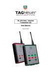
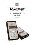
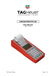
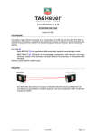
HL 680 Radio Data / Voice User Manual Version 01/2009 1. Introduction The radio set HL 680 is dedicated to transmit Timing Data from Chronoprinter 540, and also for voice communication between HL680s. The vocal communication has priority over the Data transmission. Data awaiting transmission will be stored in memory and transmitted when the channel is clear. The HL 680’s reliability during extreme weather conditions (rain, snow, sand etc…) and is the ideal radio for all situations. 2. Description 1. Adjust the Volume [VOL] Switch ON/OFF and adjust the volume. 2. Red button: function button could be programmed by the software. 3. Antenna input 4. Connecter CP 540 / Data 5. Keys ▼ and ▲ to select pre-programmed channel. 6. Key PO to P1 P0 = Call and Synchro test P1 = Reset + Acknowledge 7. LED Transmission / Busy 8. Key PTT (Push to talk) Press and hold for vocal transmission, and release to receive. 3 1 2 4 8 7 6 5 3. Accessories • Flexible antenna Connector for a flexible antenna. • Kit for BNC antenna is available (Especially for the professional antenna) WARNING Nevel carry the radio by the antenna.. Transmitting wihtout the antenna could damage the radio module. • Battery Pack To fix the Battery Pack, Place the battery against the radio and push it as shown on the arrow (1) until the locking mechanism (2) makes a small click. Removing the Battery Pack: Press the locking button (2) as show the arrow, and remove the back pack. WARNING Before fitting or removing a Battery Pack, check carefully that the radio is clean, and free from any dust or humidity. Any ingress of water or dust in the radio or the pack battery can cause damage. 4. Display 1. Power of transmission Displays three levels of power: Low 2 (1W), Low 1 (2W), no display (5W) 2. If the level of communication is not muted. 3. Indicates if the keyboard is locked 4. Indicates the charge level of the battery If the logo is displayed or flashing, the level of charge is below the programmed level. 5. Displays the working channel, channel name etc. For other symbols, refer to the ICOM user’s manual. 5. User setting The mode « user setting » is available when you switch ON the radio. This allows you to change settings or customize the operator mode. Activate the user setting: o To active the « user setting », switch ON the radio (turn the button [ VOL ], and press simultaneously the keys ▼ and ▲ o Press and hold for a couple of seconds the key [ P0 ] to access to user setting mode. Select the menu by pressing shortly the button [ P0 ]. Settings available via the user setting. Retro-light: Beep : Mute level: AF level mini: Micro sensitivity : Battery level: ON, OFF, or auto ON / OFF 0 to 255 ON / OFF 1 to 5 Display or masked Use the key ▼ and ▲ to modify the level of adjustment 6. Battery charge For a long live and an optimum use, you need to charge completely the battery pack before the first use. WARNING Switch OFF the radio during charging to ensure no damage. • • • • • Recommended charging temperature. +10°C to +40°C Range of temperature (Batt Li-Ion) -20°C to +60°C Only Use the charger ICOM (BC-119) or other model proposed by ICom or TAG Heuer (BC-152, BC-121N) NEVER use adaptator from other suppliers. NEVER use chargers from other suppliers. RECOMMENDATION Charge the battery pack provided for a minimum of 10 hours. With the Batteries Li-Ion it is not necessary to charge them and to discharge them completely to prolong their lifespan to the maximum. It is thus recommended to charge these batteries with regular intervals while taking care to limit the time of load. CAUTION! Never insert into the charger a battery pack whilst it is wet or soiled. High risk of corrosion or damage to the charger. The charger is not water proof and can easily be damaged by water ingress. Never incinerate the worn battery packs. The gases contained in the battery can cause an explosion. Never immerse the battery pack. If there is any presence orf trace of moisture on the pack, it should be immediately wiped with a dry tissue (particularly the terminals of the battery) BEFORE fixing it to the transmitter-receiver. The moisture is likely to corrode the terminals of the battery or to prevent the connection of the battery etc… Never connect the terminals of the pack battery in short-circuit. In the same way, the current can run out via the close metal objects, such as collars etc… It is thus necessary to act with precaution during transport or of the arrangement in a bag or near metal objects etc… To avoid keeping the battery pack fully loaded or completely discharged for a long period, which reduces the lifespan of the battery. In the case of prolonged nonutilization of the battery pack, it is necessary keep the system in a dry room, after a normal discharge or to use the battery until appearance of the weak witness of load, then to extract it from the transmitter-receiver. In case of a reduced capacity of the battery pack, even after the load, leave the system ON a whole night to obtain a complete discharge, then reload the battery pack completely. Replace the battery pack if the problem continues. 7. Battery box (option ref : HL 680-8 ) To use the Battery box (option) for the radio, insert 5 alkaline AA batteries (LR6) as shown on Fig N°1. The Battery Box HL680-8 is water proof and conforms to the norm JS, level 4. 1. Release the lock and open the cover as shown on the arrow 2 (fig 1) 2. Insert 5 alkaline AA batteries (LR6) (fig.2) • Use only alkaline battery • Respect the polarity. • Do not hide the extraction ribbon under the batteries. 3. Close the box cover as shown on fig 1 (arrow (2)) and check that the lock is correctly placed 4. Check carefully that the joint and the ribbon are correctly placed and do not protrude from the battery box. WARNING • • Check carefully that ALL the batteries are ALL the same type and capacity. Also take care to not use worn batteries To maintain / clean the battery connection, it is recommended to clean once per week. Fig 1 (2 (3 Fig 2 8. Connection Connect the Special data cable to the connector [SP MIC] of the radio, and tighten the screw fastening. IMPORTANT Replace the cap of connector [SP MIC] of the Radio when the Data Cable is not connected. There is no risk of water infiltration in the radio even in the absence of cap, however the connection pins can oxidize if they are in contact with moisture. 9. Accessories • Battery Box – HL 680-8 • Antenna – Connector • Nylon Case – HL 680-9 10. Startup with Chronoprinter 540 • Ensure you have all the necessary cables: Cable D-Sub 25p / Radio plug HL 680 Cable D-Sub 25p / RS 232 • Configure the CP 540 as follows: MENU (F) Parameters RS232 To PC 9600 Bds. with Flow Ctrl See chapter 5.2.9 from Chronoprinter 540 user’s manual. • Ensure that you connect the Radio to the PC 540 and switch ON before starting a new RUN (from the CP 540). Press the key [ P0 ] to test the connection between systems. The message “CONNECT” is displayed if the radios are able to connect together. If the message “FAILED” is showing, ensure that all systems are set to the same frequency and the distance is not too big (or other interference). In case of no communication during a race, you can re-initialised the system by pressing the key [ P1 ], (RESET) . All times not yet transmit are memorized into the CP 540. Trick: if you need to resend a time from a CP 540, use the function “Duplicate” from the CP 540 menu. 11. Radio Programming a. Synchro to a PC • • • • • Switch OFF the radio Connect the Radio to a PC (RS232) Run the program « CSF50.exe ». Check your configuration (COM) Press the button [ P0 ] and switch ON the radios simultaneously. The radio info should display on the software: b. Upload the config file on the PC Before modifying any parameters, download the radio config on your PC, with the button: Do not forget to save the original config. c. Program frequency Allows you to get up to 8 Banks of 16 channels BANK: N° of the bank of 16 programmed frequency TEXT: Enter name of the bank CAPA: Nb channel available Use: Nb of channel used and the frequency of each cannel (for one bank): CH X-X: N° bank – N° Channel RX: Receiver frequency (in MHz) TX: Transmitter frequency (in MHz) Tx = if similar as Rx RF POWER : Transmission power High (5W), Low 1 (2W) and Low 2 (1W) Once the parameter fields are correct, download the configuration to the radio - download Wait the until the end of the transmission (radio will display « Cloning OK ») DO NOT FORGET Save data file (*.icf) to your PC, to be able to configure other radios with exactly the same configuration. 12. Technical specification General o o o o o o o o o o o Operating temperature Radio dimensions: Weight: LCD Screen Frequency: Nb channel: Gap between channels: Antenna impedance: Power: Audio power max: Consumption (avg): -25°C to +50°C 56 x 97 x 36,4mm 250g / radio 8 characters 136-174 MHz (programmable) Max. 128 channels 12.5 MHz 50 Ohms (SMA Type) 7.2 Vdc 700 mW Transmission 5W : 1,8 A 1W : 0,7 A Std-by: 85 mA Battery accumulator Pack Li-Ion BP-22 o Type 7.2V Li-Ion (1700mAh) o Charging Temperature 0° to + 40°C o Charging Current 500mA (~ 2.5 hours) Power supply BC-145E o Primary o Secondary 230V - 50Hz - 125mA 16V - 1000mA WARNING The Radios use a frequency band which requires radio licensing Please refer to the legislations of the country in force. TAG Heuer PROFESSIONAL TIMING 6A Louis-Joseph Chevrolet 2300 la Chaux-de-Fonds Switzerland Tel : 032 919 8000 Fax : 032 919 9026 E-mail: [email protected] Http: //www.tagheuer-timing.com