1
B – User manual K-REA
K-REA
B. USER MANUAL
B.1. General preview .............................................................................................................. 5
B.1.1. Presentation of K-REA ............................................................................................. 5
B.1.2. Quick start ................................................................................................................ 7
B.1.3. Recommendations ................................................................................................... 8
B.2. Main window ................................................................................................................... 9
B.2.1. Main menu ............................................................................................................. 10
B.2.1.1. File menu ....................................................................................................... 10
B.2.1.2. Data menu...................................................................................................... 11
B.2.1.3. Wizards menu ................................................................................................ 12
B.2.1.4. Staged construction menu ............................................................................. 13
B.2.1.5. Calculation/Results menu .............................................................................. 14
B.2.1.6. Help menu ...................................................................................................... 15
B.2.2. Shortcuts ................................................................................................................ 16
B.2.2.1. Buttons bar ..................................................................................................... 16
B.2.2.2. Main window buttons...................................................................................... 17
B.2.2.3. Keyboard shortcuts ........................................................................................ 18
B.2.3. Project management zones ................................................................................... 19
B.2.3.1. Staged construction management zone......................................................... 19
B.2.3.2. Action selection zone ..................................................................................... 20
B.2.3.3. Action parameters zone ................................................................................. 23
B.2.3.4. Comments zone ............................................................................................. 23
B.3. Data menu ..................................................................................................................... 24
B.3.1. Title and options ..................................................................................................... 24
B.3.2. Soil layers .............................................................................................................. 26
B.3.3. Retaining wall ......................................................................................................... 29
B.4. Wizards .......................................................................................................................... 31
B.4.1. Wizards for the active and passive earth pressure coefficients ............................. 31
B.4.1.1. Tables for active and passive earth pressure, according to KERISEL
and ABSI ....................................................................................................... 31
B.4.1.2. COULOMB active and passive earth pressures formulas .............................. 32
B.4.1.3. RANKINE active and passive earth pressures formulas ................................ 33
B.4.2. Subgrade reaction wizard ...................................................................................... 35
B.4.2.1. BALAY formula............................................................................................... 35
B.4.2.2. SCHMITT formula .......................................................................................... 36
B.4.2.3. CHADEISSON curves .................................................................................... 37
Copyright © K-REA – TERRASOL 2004 – April 2008
1/58
B – User manual K-REA
B.4.3. EI and Rc wizard .................................................................................................... 38
B.4.3.1. Diaphragm walls............................................................................................. 38
B.4.3.2. Spaced or jointed piles ................................................................................... 39
B.4.3.3. Sheet-pile walls .............................................................................................. 42
B.5. Staged construction ..................................................................................................... 43
B.6. Calculation and results ................................................................................................ 45
B.6.1. Calculation ............................................................................................................. 45
B.6.2. Results ................................................................................................................... 45
B.7. Display options ............................................................................................................. 51
B.7.1. Layers colours ................................................................................................................... 51
B.7.2. Popup menus ......................................................................................................... 52
B.7.2.1. Popup dialogue box corresponding to the graphical display
in the main window ....................................................................................... 52
B.7.2.2. Popup menu in the synthesis tables .............................................................. 53
B.7.2.3. Popup menu in the results window ................................................................ 53
B.8. Printing .......................................................................................................................... 56
B.8.1. Printing wizard ....................................................................................................... 56
B.8.2. Phases synthesis (graphical synthesis) ................................................................. 57
BIBLIOGRAPHY……………………………………………………………………………….……58
2/58
April 2008 - Copyright © K-REA – TERRASOL 2004
B – User manual K-REA
FIGURES
Figure B 1: Main window .......................................................................................................... 9
Figure B 2: File Menu ............................................................................................................. 10
Figure B 3: Data menu ........................................................................................................... 11
Figure B 4: Wizards menu ...................................................................................................... 12
Figure B 5: Staged construction menu ................................................................................... 13
Figure B 6: Calculation/Results menu .................................................................................... 14
Figure B 7: Help menu ........................................................................................................... 15
Figure B 8: Staged construction management zone, cut into 4 zones ................................... 19
Figure B 9: Action selection zone divided into four zones ...................................................... 20
Figure B 10: Selection of the Struts action ............................................................................. 21
Figure B 11: Action selection zone ......................................................................................... 22
Figure B 12: Action parameters zone (example of an excavation with modification
of the waterlevel) ............................................................................................ 23
Figure B 13: Comments zone................................................................................................. 23
Figure B 14: Title and Options dialogue box .......................................................................... 24
Figure B 15: Soil layers dialogue box ..................................................................................... 26
Figure B 16: Retaining wall dialogue box ............................................................................... 29
Figure B 17: Tables for active and passive earth pressures by Kerisel and Absi .................. 31
Figure B 18: Calculation using the Coulomb method ............................................................. 33
Figure B 19: Calculation using the Rankine method .............................................................. 34
Figure B 20: Calculation of the subgrade reaction coefficients, using the Balay method ....... 35
Figure B 21: Rheological parameter wizard ........................................................................... 36
Figure B 22: Calculation of the subgrade reaction coefficient using the Schmitt formula ...... 36
Figure B 23: Chadeisson curves ............................................................................................ 37
Figure B 24: Calculation of the EI product for a diaphragm wall ............................................ 38
Figure B 25: Calculation of the EI product for a circular pile .................................................. 39
Figure B 26: Calculation of the EI product for steel circular piles ........................................... 40
Figure B 27: Calculation of the EI product for mixed walls ..................................................... 41
Figure B 28: Sheet-piles database ......................................................................................... 42
Figure B 29: Initial phase........................................................................................................ 43
Figure B 30: Phase 1.............................................................................................................. 44
Figure B 31: Results window, Data tab .................................................................................. 46
Figure B 32: Graphical results display for phase 2................................................................. 47
Figure B 33: Tables for results of phase 5 ............................................................................. 48
Figure B 34: Synthesis table .................................................................................................. 50
Figure B 35: Envelope curves for phases 1 to 5. ................................................................... 50
Figure B 36: Colour wizard for the soil layers......................................................................... 51
Figure B 37: Popup dialogue box for the graphical display in the main window .................... 52
Figure B 38: Additional examples of the popup dialogue box ................................................ 52
Figure B 39: Right-click menu in the soil layers table............................................................. 53
Figure B 40: Popup menu on the curves ................................................................................ 54
Figure B 41: Popup menu on a results table .......................................................................... 55
Figure B 42: Printing wizard ................................................................................................... 56
Figure B 43: Phases synthesis ............................................................................................... 57
Copyright © K-REA – TERRASOL 2004 - April 2008
3/58
B – User manual K-REA
4/58
April 2008 - Copyright © K-REA – TERRASOL 2004
B – User manual K-REA
B.1. General preview
B.1.1. Presentation of K-REA
K-REA is a Windows®-based software enabling to design retaining walls, using the subgrade
reaction method.
The Windows® format allows for a user-friendly interface and a really easy data input.
Moreover, the schematic display of each construction phase makes it easy to check the
project data.
You may define soil and wall properties, as well as construction phases, directly from the
main window.
The main functions or actions available in K-REA are listed below and grouped into different
categories:
The general options of a project include:
•
•
•
•
•
•
units (homogeneous either to MN, kN or t);
water weight;
orientation of the vertical axis, in order to work either with depths or with levels;
calculation options (number of iterations and steps);
output options (graphics, language, limiting/mobilised earth resistance ratio);
option to take anchors buckling into account.
Soil and wall properties include:
•
•
•
•
•
•
geometrical and geotechnical properties of the soil layers;
groundwater level for each soil layer;
parameters related to the subgrade reaction calculation method, using wizards for
the coefficients k0 (Jaky), ka, kp (Kérisel and Absi, Coulomb or Rankine), ca, cp
(Caquot) and kh (Balay, Schmitt or Chadeisson);
product of inertia of the wall, depending on the wall type (diaphragm wall, spaced
or jointed piles, sheet-pile wall). Wizards are available;
cylindrical rigidity in the case of a circular wall. Wizards are available;
The option to change the wall width (default width is one linear meter).
The actions available to define the construction stages include:
•
•
•
•
•
•
•
Caquot, Boussinesq and Graux surcharges (which can be later modified or
removed) either on uphill or downhill sides;
Horizontal loads, external moments or rotation springs to be applied directly onto
the wall;
Excavations, changes of the waterlevel, application of Caquot surcharges at the
excavation level, either on uphill or downhill sides;
Excavations with berms;
Sheeting installation;
Simulation of a discontinuous wall (with its effect on earth pressures), and of the
sheeting installation;
Fill (downhill or uphill) with application of a Caquot surcharge;
Copyright © K-REA – TERRASOL 2004 - April 2008
5/58
B – User manual K-REA
•
•
•
•
•
•
Installation and removal of anchors (struts, prestressed anchors), or modification
the anchors stiffness and prestress force;
Modification of the overall product of inertia on parts of the wall;
Wall extension upwards ("wall raising");
Modification of soil properties (independently for each layer, downhill and/or
uphill): active/passive earth pressure coefficients, subgrade reaction
coefficients, …) ;
Hydraulic gradients uphill or downhill;
Definition of a maximum passive pressure in order to simulate a maximal
resistance for the wall.
The main options, soil properties and wall properties are available from the main menu, and
are displayed in dialogue boxes. Once they have been validated, they are displayed on the
graphical representation of the project in the main window.
Actions, such as struts installation, excavations or surcharges, are available in the action
selection zone in the main window. Their graphical representation is also displayed in the
main window after validation.
Finally, both calculation and results display can be requested from the main window.
All these steps are detailed in this part of the manual.
The mechanical properties of the actions available in K-REA are detailed in Part C –
Technical manual.
Examples and tutorials are presented in Part D – Tutorials and examples.
K-REA DATA FILES ARE SAVED AS .P20 FILES AND RESULTS FILES ARE SAVED AS
.REA FILES.
6/58
April 2008 - Copyright © K-REA – TERRASOL 2004
B – User manual K-REA
B.1.2. Quick start
1. Start K-REA by clicking either the Start menu shortcut or the desktop shortcut.
2. Select New Project.
3. Set the dimensions and options for the project by selecting the Data menu, then Title
and Options. Fill in the text boxes and validate.
4. Set the soil layers properties by selecting the Data menu, then Soil layers.
5. Set the wall properties by selecting the Data menu then Retaining wall (available
only after input of the soil properties).
6. Apply the actions for the initial phase if any: select them in the action selection zone,
define their properties, and Validate them so that they are displayed on the graphical
representation in the main window.
7. Click on Add in the staged construction management zone. Apply the actions for the
new calculation phase, define their properties using the action selection zone, and
Validate them.
8. Repeat this procedure until the final phase is reached.
9. Run the calculation by clicking on the Calculation button below the action selection
zone (the calculations can also be run after definition of each phase depending on the
user's habits).
10. Finally, click on the Results button in the action selection zone to open the detailed
results window.
Copyright © K-REA – TERRASOL 2004 - April 2008
7/58
B – User manual K-REA
B.1.3. Recommendations and notes
¬ K-REA is intended to be used with anchors located in the soil on the right side of
the wall, and struts located on the left side of the wall. So the main excavation must be
located on the left of the wall (downhill side). This does not prevent a temporary
excavation level deeper on the right side than on the left side of the wall.
¬ The Caquot surcharge, Maximal pressure and Reduced pressure actions can
only be applied in the initial phase. Consequently, these actions can only be applied once,
and their parameters are valid for the whole staged construction of the project. The Maximal
pressure action can never be modified. On the contrary, the Reduced pressure action can be
cancelled by sheeting installation, and the Caquot surcharge action is automatically
cancelled on a given side when applying an excavation or fill on this very same side.
¬ Some actions have to be preceded by an Excavation-Water action. These are:
Sheeting installation, excavation with Berm and Hydraulic gradient. Apply an ExcavationWater action first, then, in the same phase, apply one of the three actions listed before. In the
action parameters zone, the following instructions should appear:
Excavation-Water
or Excavation Water
or Excavation-Water
Berm
Sheeting installation
Hydraulic gradient
¬When fills are installed, they are taken into account with p i = k i .σ v' . Successive fills
can be defined in successive phases.
¬ The Sheeting installation action (for soldier-pile walls) is valid only if the
Reduced pressure action has been defined in the initial phase.
¬ When installing anchors, the "gap" in the shear forces is equal to the value of the
prestress forces. Zero prestress forces may account for continuity in the shear forces
diagram.
¬ Anchors and other forces applied to the wall can be superposed at the same point
of the wall and can all be considered as elementary forces acting onto the wall. The total
number of each type of anchor cannot exceed 50 for the whole project.
¬ If the elementary wall width is different from 1 m, do not forget to input all the
values that depend on this elementary wall width proportionally to it. Such values can be: the
wall properties (EI, Rc), the stiffness of struts or anchors (K), exterior forces applied to the
wall (P, M, R), reduced pressure coefficients…
The results displayed by K-REA are also proportional to the elementary wall width.
8/58
April 2008 - Copyright © K-REA – TERRASOL 2004
B – User manual K-REA
B.2. Main window
The main window in K-REA enables to reach all features necessary to set up a project. The
secondary windows are the data input dialogue boxes, the wizards windows, and the results
window.
Action
selection
zone
Staged construction management zone
Action parameters zone
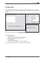
Figure B 1: Main window
The main window includes:
• The menu bar;
• Buttons, on the button bar and in the window itself;
• The staged construction management zone;
• A comments zone;
• The action selection zone;
• The action parameters zone (not shown on figure B 1).
The following chapters detail how to use each part of the main window.
Copyright © K-REA – TERRASOL 2004 - April 2008
9/58
B – User manual K-REA
B.2.1. Main menu
The main menu options are available by left-clicking on their label.
B.2.1.1. File menu
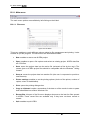
Figure B 2: File Menu
This menu enables to reach different options related to file management and printing. It also
enables to quit the program. The sub-menus are described hereafter:
•
New: enables to start a new K-REA project.
•
Open: enables to open a file explorer and select an existing project. K-REA data files
are .P20 files.
•
Save: saves the project data into the active file (selected at first by the user). The
names given to K-REA project files should be compatible with the Windows® writing
formats.
•
Save as: saves the project data into another file (the user is requested to provide a
new filename).
•
Printer settings: enables to set the printing options (choice of the printer, number of
copies, colour or black&white).
•
Print: opens the printing dialogue box.
•
Copy to clipboard: copies a screenshot of the data or of the results in order to paste
them afterwards into another Windows® file.
•
Recent files: this part of the file menu displays shortcuts to the last four files opened
in K-REA. These recent files are available only if they have not been moved or
erased.
•
Quit: enables to quit K-REA.
10/58
April 2008 - Copyright © K-REA – TERRASOL 2004
B – User manual K-REA
B.2.1.2. Data menu
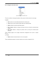
Figure B 3: Data menu
This menu enables to display the project data dialogue boxes. These data include: the
general options for the project, the soil layers properties, and those of the wall. Chapter B.3.
Data provides detailed explanations about the data in K-REA.
•
Title and Options: enables to display the corresponding dialogue box, to type in a
title for the project, and to set its general options (units, calculation step, number of
iterations per phase, buckling option, etc.).
•
Soil layers: enables to set the soil properties (weights, specific properties, subgrade
reaction coefficients, etc.).
•
Retaining wall: enables to set the wall properties (dimensions, properties, etc.).
IN ORDER TO DEFINE A NEW PROJECT PROPERLY, IT IS NECESSARY TO BROWSE
SUCCESSIVELY ALL OPTIONS IN THIS MENU.
Copyright © K-REA – TERRASOL 2004 - April 2008
11/58
B – User manual K-REA
B.2.1.3. Wizards menu
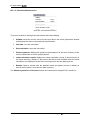
Figure B 4: Wizards menu
This menu enables to display the different dialogue boxes for wizards. They provide help to
define the active/passive earth pressure coefficients or subgrade reaction coefficients. The
use and contents of the wizards dialogue boxes are described in chapter B.4. Wizards.
•
Tables for active and passive earth pressure by KERISEL and ABSI: enables to
calculate the active/passive earth pressure coefficients, reading the J. Kérisel and E.
Absi charts [1].
•
COULOMB Active and passive earth pressure formula: calculates the active and
passive earth pressure coefficients using the Coulomb formula [2].
•
RANKINE Active and passive earth pressure formula: calculates the active and
passive earth pressure coefficients using the Rankine formula [2].
•
Subgrade reaction coefficients: enables to calculate the subgrade reaction
coefficients using the Balay or Schmitt formulae, or the Chadeisson charts [3] [4] [5].
•
Layers colours: opens the soil properties dialogue box. Double-click on the colour
rectangle for a given soil layer in order to open the dialogue box for layers colours.
12/58
April 2008 - Copyright © K-REA – TERRASOL 2004
B – User manual K-REA
B.2.1.4. Staged construction menu
Figure B 5: Staged construction menu
This menu enables to manage the phases of the project, and the actions for each stage.
PHASES
•
Add: creates a new calculation phase after the existing ones.
•
Insert:: inserts a new calculation phase before the selected phase.
•
Delete: deletes the selected calculation phase.
•
Move forward: enables to change the phases order by moving the selected phase
forward.
•
Move back: enables to change the phases order by moving the selected phase
backward.
These changes appear in the staged construction management zone (refer to chapter
B.2.3.1).
ACTIONS
•
Delete: deletes the selected action in the current phase.
These modifications appear in the action selection zone (refer to chapter B.2.3.2).
Copyright © K-REA – TERRASOL 2004 - April 2008
13/58
B – User manual K-REA
B.2.1.5. Calculation/Results menu
Figure B 6: Calculation/Results menu
This menu enables to manage the calculations and results display.
•
Validate: saves the current values for the input data in the action parameters window
and displays the data on the graphical representation.
•
Calculate: runs the calculation.
•
Stop calculation: stops the calculation.
•
Phases synthesis: displays the graphical representation as well as a summary of the
actions parameters for all the project phases.
•
Latest calculation results: displays the latest calculation results, if they still exist (in
the same directory). Beware: if the project data have been modified since the latest
calculation, the displayed results will not correspond to the new data anymore.
•
Results: opens a window with the detailed results per phase (curves or tables) as
well as the envelope curves and the data summary.
The Phases synthesis and Results windows are introduced in chapters B.8.2 and B.6.2.
14/58
April 2008 - Copyright © K-REA – TERRASOL 2004
B – User manual K-REA
B.2.1.6. Help menu
Figure B 7: Help menu
This last menu enables to reach the help sub-menus and the software information.
•
Help: enables to reach the help menu.
•
About: provides software information (for example the version of the software).
•
TERRASOL website: this is a link to the TERRASOL website.
Copyright © K-REA – TERRASOL 2004 - April 2008
15/58
B – User manual K-REA
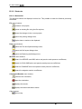
B.2.2. Shortcuts
B.2.2.1. Buttons bar
The shortcut buttons are displayed on this bar. They enable to reach the features previously
described:
File menu buttons:
creates a new project;
opens an existing file using the file explorer;
saves the changes in the current project;
opens the printing dialogue box;
copies data or results to the clipboard.
Data menu buttons:
opens the Title and Options dialogue box;
opens the Soil layers dialogue box;
opens the Retaining wall dialogue box.
Wizards menu buttons:
wizard for KERISEL and ABSI active and passive earth pressure coefficients;
wizard for COULOMB active and passive earth pressure coefficients;
wizard for RANKINE active and passive earth pressure coefficients;
wizard for subgrade reaction coefficients.
Calculation/Results menu buttons:
performs the calculation;
stops the calculation;
displays the results;
displays the latest calculation results.
Other buttons:
Online help.
16/58
April 2008 - Copyright © K-REA – TERRASOL 2004
B – User manual K-REA
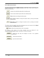
B.2.2.2. Main window buttons
The buttons at the bottom of the staged construction management zone are shortcuts for the
Staged construction menu, PHASES sub-menu (Add, Insert, Delete, Move forward et
Move back commands).
creates a new calculation phase after the existing ones.
inserts a new calculation phase before the selected phase.
Delete: deletes an existing calculation phase.
Move forward: enables to change the phases order by moving the selected
phase forward.
Move back: enables to change the phases order by moving the selected
phase backward.
The buttons under the staged construction management zone are shortcuts for the Staged
construction menu, ACTION sub-menu (Delete).
Delete: deletes the selected action in the current phase.
The buttons at the bottom of the action selection zone are shortcuts for the
Calculation/Results menu (Validate, Calculation or Results commands).
saves the input data and displays the data on the graphical
representation.
performs the calculation.
opens the results window.
Copyright © K-REA – TERRASOL 2004 - April 2008
17/58
B – User manual K-REA
B.2.2.3. Keyboard shortcuts
Keyboard shortcuts are another way to reach the features of K-REA directly. Here is the list
of the keyboard shortcuts.
•
Ctrl+N: Creates a new project;
•
Ctrl+O: Opens an existing file using the file explorer;
•
Ctrl+S: Saves the current file;
•
Ctrl+P: Opens the printing wizard dialogue box;
•
Ctrl+Q: Runs the calculation;
•
Ctrl+A: Stops the calculation;
•
Ctrl+R: Opens the results window.
These shortcuts are indicated in the corresponding sub-menus.
18/58
April 2008 - Copyright © K-REA – TERRASOL 2004
B – User manual K-REA
B.2.3. Project management zones
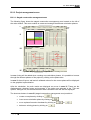
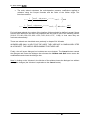
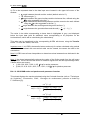
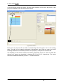
B.2.3.1. Staged construction management zone
The following figure shows the staged construction management zone located on the left of
the main window. This zone enables to create and manage the different calculation phases.
I
II
III
IV
Figure B 8: Staged construction management zone, consisting in 4 zones
In zone I, tabs will be added when creating new calculation phases. It is possible to browse
through the different phases of the project by clicking on the phase tabs.
In zone II, the soil layers, wall and all validated actions for the current phase will be displayed
on the graphical representation.
After the calculation, the main results are displayed as curves in zone III. These are the
displacements, shearing forces and moments. If the option was selected in the “Title and
options” dialogue box, the limited/mobilised earth resistance ratio will also be displayed.
The shortcuts buttons in zone IV (staged construction management zone) enable to:
•
create a new phase by clicking on
•
insert a new calculation phase by clicking on
•
move a phase forward or backward by clicking on
•
delete an existing phase by clicking on
Copyright © K-REA – TERRASOL 2004 - April 2008
or
19/58
B – User manual K-REA
Note 1: the curves can be enlarged by double-clicking them, so that they fill all the staged
construction management zone. It is then possible to click on a point of the curve to display
its properties at the bottom of the main window. Right-clicking on these curves enables to
reach the popup menu (refer to chapter B.6.2.3). Double-clicking on the curve again enables
to bring the curve back to its initial size.
Note 2: in zone II, the graphical representation of the soil layers, wall and actions is scaled
only vertically, not horizontally. This is just a schematic sketch, not a true-scale crosssection. Do not trust the length of an anchor, for example, nor the wideness of a berm or that
of a surcharge.
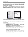
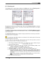
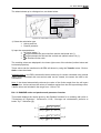
B.2.3.2. Action selection zone
II
I
III
IV
Figure B 9: Action selection zone divided into four zones
The action selection zone appears in the upper-right corner of the main window. It enables to
define actions for the selected calculation phase.
In K-REA, the actions represent temporary or permanent loads applied onto the ground or
the wall. They also enable to define earthworks (the program will calculate the corresponding
effects onto the wall).
These actions are grouped into different categories:
20/58
•
Initial phase: includes 3 types of actions available only in the initial phase:
Caquot surcharge, reduced pressure and maximal pressure. These actions can
be applied only once and remain valid during the whole project.
•
Loads-Forces-Moments: includes 2 types of surcharges applied onto the ground
(Boussinesq and Graux surcharges), 2 types of loads applied directly onto the
wall (Couple and horizontal load), as well as linear forces.
•
Earthworks: includes the variations of the groundlevel due to simple excavations,
excavations with berms or with sheeting installation, and to fills.
•
Anchors-Wall: includes 3 types of anchors (struts, anchors and rotation springs).
Several anchors can be placed at the same point on the wall. This category
includes 2 types of wall modifications as well (modification of the wall stiffness
and extension of the wall upwards).
April 2008 - Copyright © K-REA – TERRASOL 2004
B – User manual K-REA
•
Soil layers: this category includes an action that enables to modify the properties
of the soil layers (each property can be changed individually in a phase).
•
Hydraulic: this category includes one single action, which is the definition of a
hydraulic gradient.
The categories are displayed in blue in zone I (action selection zone).
Zone I includes a listbox for each category, so that you can browse through all actions types
available for each category.
The following table summarises all available actions:
Actions selection
¬Initial phase
¬Caquot surcharge
¬Reduced pressure
¬Maximal pressure
¬Loads-Forces-Moments
¬Boussinesq surcharge
¬Graux surcharge
¬Moments
¬Horizontal load on the wall
¬Linear force
¬Earthworks
¬Excavation-Water
¬Fill
¬Berm
¬Sheeting installation (soldier-pile wall)
¬Anchors-Wall
¬Struts
¬Anchors
¬Rotation spring
¬Modification of the wall bending stiffness
¬Wall raising
¬Soil properties
¬New soil properties (modification of existing ones)
¬Hydraulic
¬Hydraulic gradient
To select an action, click on the scrolling arrow of the desired listbox, and select the proper
action.
Figure B 10: Selection of the Struts action
Copyright © K-REA – TERRASOL 2004 - April 2008
21/58
B – User manual K-REA
Then click on the transfer button
next to the listbox in order to transfer the action into the
list of applied actions for the current phase (zone III).
The corresponding action parameters zone is then displayed, right under the action selection
zone. The parameters for the selected action should be defined. This specific zone is
described in the next chapter.
All actions in a phase are listed in the order in which they have been defined, in zone III.
The mechanical properties of these actions are described in part C – Technical manual.
The current phase is the one displayed in zone II. It is possible to rename each phase by
replacing the default title in zone II with a new name.
The “Envelope” checkbox enables to define the phases which will be used by the program to
calculate the envelope curves. For example:
•
If no “Envelope” box is checked in the phase tabs, only one envelope curve will
be shown. This default curve includes the maximal displacements, shear forces
and moments calculated for all phases.
•
If a project includes five phases plus the initial phase, and if the “Envelope” box is
checked in phase 3, two envelope curves will be available: one with the maximal
displacements, shear forces and moments for phases 1 to 3, and the other curve
with those maximal data for phases 4 to 5.
Figure B 11: Action selection zone
22/58
April 2008 - Copyright © K-REA – TERRASOL 2004
B – User manual K-REA
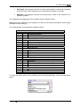
B.2.3.3. Action parameters zone
Figure B 12: Action parameters zone (example of an excavation with modification of the waterlevel)
The action parameters zone appears in the lower right corner of the main window, right
under the action selection zone.
Each action in K-REA is associated with a specific set of action parameters. In general, the
action parameters zone is divided into two parts. The left part enables for the data input and
the right part shows a schematic diagram that illustrates the action parameters.
Figure B 12 shows the parameters zone corresponding to the “excavation-water” action. The
checkboxes and edit boxes appear in white. The example illustrates a "simple" excavation at
level 172 m with a water table at 171 m and no surcharge applied on the bottom of the
excavation.
Parameters for all actions are described in Part C – Technical manual.
B.2.3.4. Comments zone
Figure B 13: Comments zone
The comments zone is located right under the staged construction management zone. This
zone enables to type in comments for the current phase. These comments are then
displayed in the results window as well as in the results synthesis.
Copyright © K-REA – TERRASOL 2004 - April 2008
23/58
B – User manual K-REA
B.3. Data menu
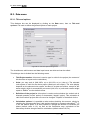
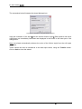
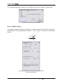
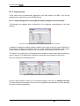
B.3.1. Title and options
This dialogue box can be displayed by clicking on the Data menu, then on Title and
options. It is used to define the general options of each project.
Figure B 14: Title and Options dialogue box
The checkboxes, radio buttons and data input boxes are white and can be edited.
This dialogue box is divided into the following zones:
•
Title/Project number: this zone is used to type in a title for the project (the content of
this box has no impact on the calculation).
•
Units: you may work in (MN, MPa, m) or (kN, kPa, m) or (t,t/m2,m). The selected
units system is valid for the whole project (data input and output). The units display
depends on the selected units system, but there is no data conversion, except for the
water weight, which is automatically converted. (kN ,kPa, m) units and a water weight
equal to 10kN/m3 are the default values.
•
Definition of the project in: this option is used to select whether the vertical axis is
directed upwards (“levels” option) or downwards (“depths” option). This orientation is
valid for the whole project and can never be changed. “Depths” is the default choice.
•
Calculation options: it is possible to take anchors buckling into account, simply by
checking the corresponding box (“add anchors buckling in moments calculation”(1)). It
is not the default option. It is also possible to change the Number of iterations per
phase (default value is 10), as well as the Calculation step, equivalent to the
elementary division along the wall for calculations (default value is 0,5 m).
24/58
April 2008 - Copyright © K-REA – TERRASOL 2004
B – User manual K-REA
Note: the suitable range for the calculation step is between the wall thickness and a value
that would limit the number of wall elements to 30.
(1)
: the buckling option is associated to the anchor action and enables to take the vertical
force created by the anchor into account in the moments calculation.
•
Curves display: checking the box “same scale for curves” makes sure that curves
for all phases will have the same scale. This is the default option.
•
Output display: checking the box “Display ratio limited/mobilised earth resistance”
ensures that this ratio is displayed on the main screen, in the results window and on
the printouts. This is the default choice.
•
Language for output: this choice enables to select the language for printouts.
Copyright © K-REA – TERRASOL 2004 - April 2008
25/58
B – User manual K-REA
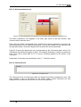
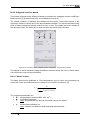
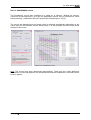
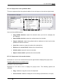
B.3.2. Soil layers
This dialogue box is displayed when clicking on the Data menu and then Soil layers. It
enables to define all soil properties for each soil layer. All those properties are used in the
calculation.
Synthesis table
Data input zone
Figure B 15: Soil layers dialogue box
This dialogue box is divided into two parts. The upper part includes a synthesis table, which
displays the data and enables to select a layer. The bottom part is the input zone, which
enables to define or change the properties for the layer currently selected in the table.
The input data is automatically validated when clicking again in the synthesis table.
In the data input zone, the properties for each layer should be fully defined, starting from the
upper layer:
•
•
•
•
•
•
•
•
•
•
26/58
The name of the soil layer;
Zc: top level of the layer (m);
Zwater: groundwater level (the default value is that of the previous layer) (m);
PVh: soil weight (above water level) (MN/m3, kN/m3, t/m3);
PVd: submerged soil weight (below water level) (MN/m3, kN/m3, t/m3);
Phi: internal friction angle (°);
c: cohesion (MPa,kPa,t/m2);
dc: variation of the cohesion per meter depth (MPa/m, kPa/m, t/m2/m);
δa/ϕ: active interface friction;
δp/ϕ: passive interface friction;
April 2008 - Copyright © K-REA – TERRASOL 2004
B – User manual K-REA
•
•
•
•
•
•
•
•
•
k0: coefficient of earth pressure at rest;
ka: horizontal active earth pressure coefficient;
kp: horizontal passive earth pressure coefficient;
kd: unloading ratio;
kr: reloading ratio;
ca: coefficient of active pressure applied to cohesion;
cp: coefficient of passive pressure applied to cohesion;
kh: subgrade reaction coefficient (MN/m3, kN/m3, t/m3);
dkh: variation of the subgrade reaction coefficient per meter depth (MN/m3/m,
kN/m3/m, t/m3/m).
Note 1: the unloading and reloading ratios enable to take the unloading and reloading effect
on the variation of horizontal forces that soils apply onto the wall: initial pressure at zero
displacement and plasticity levels are modified (refer to chapter C.4.3.).
kd = kr = k0 if soil consolidation is not taken into account.
If the material is perfectly elastic then k d =
υ
1−υ
with υ = Poisson ratio.
If the material is uncompressible, then υ = 0.5 and kd = 1. This is the case when sollicitations
are applied too quickly for an efficient draining, or when soils are largely overconsolidated.
The paper [5] in the bibliography suggests a formula for the calculation of kd (depending on
the OCR value).
In general, by symmetry, kr=kd.
Note 2: wizards for the various coefficients are available using the buttons on the dialogue
box.
There are 4 automatic wizards (no need to enter new parameters):
•
The k0 Jaky wizard calculates k0 using the Jaky formula: k 0 = 1 − sin ϕ , and
displays the value in the corresponding edit box.
•
The Rankine wizard calculates the values of ka and kp using the Rankine formulas,
and displays them in the corresponding edit boxes. The formulas are:
⎛π ϕ ⎞
⎛π ϕ ⎞
k a = tan 2 ⎜ − ⎟ and k p = tan 2 ⎜ + ⎟ .
⎝4 2⎠
⎝4 2⎠
•
•
The kd=k0 wizard copies the value of k0 into the kd box automatically.
The kr=k0 wizard copies the value of k0 into the kr box automatically.
There are also 2 wizards with dialogue boxes:
•
The ka/kp wizard calculates the active/passive pressure coefficients using one of the
three following methods: Kérisel & Absi tables, Coulomb formula or Rankine
formulas.
Copyright © K-REA – TERRASOL 2004 - April 2008
27/58
B – User manual K-REA
•
The ca/cp wizard calculates the active/passive pressure coefficients applied to
cohesion using the Caquot formulas and the value of the friction angle. The
formulas used are:
ca =
cp =
1
tan ϕ
⎤
1 ⎡ cos δ a − sin ϕ cos α −(α −δ a ) tan ϕ
e
cos δ a − 1⎥ and
⎢
tan ϕ ⎣
1 + sin ϕ
⎦
⎡ cos δ p + sin ϕ cos α (α +δ p ) tan ϕ
⎤
sin δ
e
cos δ p − 1⎥ with sin α =
⎢
sin ϕ
1 − sin ϕ
⎣
⎦
For both latest wizards, the values of the interface frictions should be defined, except if these
frictions were defined in the main soil properties and are equal to one of the following values:
{0.99 ;0.75 ;0.66 ;0.50 ;0.33 ;0.00 ;-0.33 ;-0.50 ;-0.66 ;-0.75 ; -0.99}. In that case they are
retrieved automatically.
Those two wizards are described more precisely in chapter B.4. Wizards.
WIZARDS ARE ONLY A HELP FOR THE USER, THEY ARE NOT A COMPULSORY STEP
IN A PROJECT. THE USER IS RESPONSIBLE FOR THEIR USE.
Finally, the soil layers dialogue box includes two more buttons. The Cancel button cancels
the changes and closes the dialogue box whereas the Validate and Quit button saves the
modified data and closes the dialogue box.
Note 3: clicking on the X button in the title bar of the window closes the dialogue box without
saving the changes (the X button is equivalent to the Cancel button).
28/58
April 2008 - Copyright © K-REA – TERRASOL 2004
B – User manual K-REA
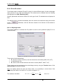
B.3.3. Retaining wall
This dialogue box is opened when clicking on the Data menu, then on Retaining wall. It
enables to define the wall properties that will be used during the calculation.
Figure B 16: Retaining wall dialogue box
The wall can be defined in two different ways: either using its Product of inertia, or using its
Thickness and Young’s modulus. The choice is made using the radio buttons in the upper
part of the dialogue box.
Two additional options may be selected using checkboxes. The Circular wall option enables
to display an additional column in the table below, in order to set the cylindrical rigidity of
such a circular wall.
The Advanced properties option enables to display and define the elementary wall width L.
This value is set to 1 m by default.
The elementary wall width is taken as a reference for the whole project. All the input
data should depend on this value.
In order to define the wall properties, select and fill in the cells of the input table, as well as
the edit box below the table. The different parameters are:
•
•
•
•
•
•
•
The Young’s modulus of the wall: to be defined if the wall is defined using its
thickness (MPa, kPa, t/m2);
Z: top level of the wall (m);
EI: product of inertia of the wall (as a function of the elementary width), to be
defined if requested to do so (MN.m2, kN.m2, t.m2);
e: thickness of the wall, to be defined if requested to do so (m);
Cylindrical rigidity: to be defined if the wall is circular (MN/m3,kN/m3,t/m3);
L: elementary wall width, either per linear meter; or per element (panel width for
example). The default value is 1 m (input and calculations per linear meter). In
case this value has to be changed, make sure that the advanced properties box
is checked.
Note: if various sections of the wall have different widths, it is recommended to
work per linear meter for all sections and for the whole project.
Zp: bottom level of the wall (m).
Copyright © K-REA – TERRASOL 2004 - April 2008
29/58
B – User manual K-REA
Note 1:
•
Here is the formula for the EI product, for a concrete rectangular section of diaphragm
wall:
L * e3
12
EI = Econcrete *
Econcrete = concrete Young’s modulus (MPa, kPa, t/m2)
e = wall thickness (m)
L = wall elementary width (m)
•
Formula for the cylindrical rigidity, for a concrete diaphragm wall, with e<<R:
Rc =
Econcrete * e
R2
Econcrete = concrete Young’s modulus (MPa, kPa, t/m2)
e = wall thickness (m)
R = curvature radius (m)
•
Formula for the EI product for a discontinuous wall (soldier-pile wall). For a soldier-pile
wall, only the piles rigidity is usually taken into account:
EI =
( EI ) pile
d
*L
d = spacing between piles axis (m)
L = wall elementary width (m)
Note 2: a Wizard is available to calculate the product of inertia and the cylindrical rigidity per
linear meter, depending on the type of wall (diaphragm wall, spaced or jointed piles, and
sheet-pile wall). Refer to chapter B.4.3. Wizards for further information.
WIZARDS ARE ONLY A HELP FOR THE USER, THEY ARE NOT A COMPULSORY STEP
IN A PROJECT. THE USER IS RESPONSIBLE FOR THEIR USE.
30/58
April 2008 - Copyright © K-REA – TERRASOL 2004
B – User manual K-REA
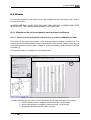
B.4. Wizards
The wizards proposed in the Wizards menu are independent from the project, and can thus
be used at any time.
WIZARDS ARE ONLY A HELP FOR THE USER, THEY ARE NOT A COMPULSORY STEP
IN A PROJECT. THE USER IS RESPONSIBLE FOR THEIR USE.
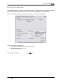
B.4.1. Wizards for the active and passive earth pressure coefficients
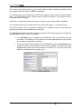
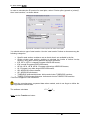
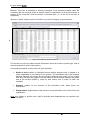
B.4.1.1. Tables for active and passive earth pressure, according to KERISEL and ABSI
This wizard is the exact reproduction of the work by Kérisel and Absi, published by "Les
Presses de l’Ecole Nationale des Ponts et Chaussées", under the title “Tables de pression et
butée des terres de Kerisel et Absi” (Tables for active and passive earth pressure by Kérisel
and Absi) [1].
This wizard consists in a dialogue box as shown below:
1
2
Figure B 17: Tables for active and passive earth pressures by Kerisel and Absi
1) Select the table type you want to use in the listbox in the upper right part of the window
• Passive earth pressure, weighted cohesionless soil, no surcharge;
• Active earth pressure, weighted cohesionless soil, no surcharge;
• Weightless cohesionless soil, with surcharge.
Copyright © K-REA – TERRASOL 2004 - April 2008
31/58
B – User manual K-REA
2) Fill in the
window:
•
•
•
requested data in the data input zone located in the upper left corner of the
•
λ: angle between the wall and the vertical (default value is 0°);
φ’: friction angle (°);
β: angle between the ground surface and the horizontal line, defined using the
β/φ’ ratio suggested in the list (°);
δ: angle between the lateral earth pressure and the normal to the wall, defined
using the δ/φ’ ratio suggested in the list (°);
α: angle between the surcharge and the ground surface (°);
•
Ω: angle between the ground surface and the wall ( =
•
π
2
+ β − λ ) (°).
The value in the table corresponding to these data is highlighted in grey, and displayed
below the input data (with an additional value corresponding to its projection on the
horizontal axis, which will be used during the calculations).
This value can be transferred to the corresponding K-REA edit boxes, using the Transfer
button. To close the wizard, click Quit.
Important note 1: In K-REA, the transfer button works only for values calculated using vertical
walls! Values calculated with non-vertical walls can be viewed, but cannot be used in the
calculations.
Note 2: K-REA uses a linear interpolation to determine values between those indicated in the
table cells.
Note 3: the wizard automatically retrieves the value of the friction angle from the soil layers
dialogue box. It also retrieves the values of interface angles from the soil layers dialogue box,
if these values are among:
• {1,00 ;0,66 ;0,00 ;-0,66 ;-1,00} δa/ φ’ for active pressures;
• {0,66 ;0,5 ;0,33 ;0,00 ;-0,33 ;-0,5 ;-0,66 ;-1,00} δp/ φ’ for passive pressures.
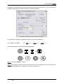
B.4.1.2. COULOMB active and passive earth pressures formulas
This wizard displays the results calculated using the Coulomb formulas (refer to "Techniques
de l’ingénieur"; Construction; C242; “Ouvrages de soutènement, pression et butée“,by
F. Schlosser [2]):
ka =
kp =
32/58
cos 2 (λ − φ )
⎡
sin (φ + δ ) * sin (φ − β ) ⎤
cos(λ + δ ) * ⎢1 +
⎥
cos (λ + δ ) * cos (λ − β ) ⎦
⎣
2
cos 2 (λ + φ )
⎡
sin (φ − δ ) * sin (φ + β ) ⎤
cos(λ + δ ) * ⎢1 −
⎥
cos(λ + δ ) * cos(λ − β ) ⎦
⎣
2
April 2008 - Copyright © K-REA – TERRASOL 2004
B – User manual K-REA
The wizard shows up in a dialogue box, as shown below:
2
1
Figure B 18: Calculation using the Coulomb method
1) Select the calculation type:
• Active pressure;
• Passive pressure.
2) Input the requested data:
• φ: friction angle (°);
• β: angle between the ground surface and the horizontal axis (°);
• λ: angle between the wall and the vertical axis (default value is 0) (°);
• δ/φ: interface friction ratio.
The resulting values are displayed in the lower right corner of the window (inclined value and
horizontal projection).
These values can be transferred to K-REA edit boxes by using the Transfer button. Click on
Quit to close the wizard.
Important note 1: In K-REA, the transfer button works only for values calculated using vertical
walls! Values calculated with non-vertical walls can be viewed, but cannot be used in the
calculations.
Note 2: the wizard automatically retrieves the value of the friction angle from the soil layers
dialogue box. It also retrieves the values of interface angles from the soil layers dialogue box,
if these values are included in the range from -1.00 to 1.00.
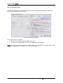
B.4.1.3. RANKINE active and passive earth pressures formulas
This wizard displays the results given by the Rankine formulas for a retaining wall (refer to
"Techniques de l’ingénieur"; Construction; C242; “Ouvrages de soutènement, pression et
butée” by F. Schlosser [2]):
⎡ cos β − cos 2 β − cos 2 ϕ ⎤
⎥ cos β
ka = ⎢
⎢⎣ cos β + cos 2 β − cos 2 ϕ ⎥⎦
⎡ cos β + cos 2 β − cos 2 ϕ ⎤
⎥ cos β
kp = ⎢
⎢⎣ cos β − cos 2 β − cos 2 ϕ ⎥⎦
Copyright © K-REA – TERRASOL 2004 - April 2008
33/58
B – User manual K-REA
The screenshot below illustrates the wizard dialogue box:
Figure B 19: Calculation using the Rankine method
Input the inclination of the slope β and the internal friction angle ϕ. Both passive and active
coefficients are immediately calculated and displayed in the boxes in the lower part of the
dialogue box.
Note: the wizard automatically retrieves the value of the friction angle from the soil layers
properties.
These values can also be transferred to the data input boxes, using the Transfer button.
Click on Quit to close the wizard.
34/58
April 2008 - Copyright © K-REA – TERRASOL 2004
B – User manual K-REA
B.4.2. Subgrade reaction wizard
This wizard proposes three different methods to estimate the subgrade reaction coefficient:
Balay formula [3], Schmitt formula [4], and Chadeisson curves [5].
The wizard consists in a dialogue box divided into three parts. Three radio buttons in the
upper part enable to choose one of the three available methods. The values calculated using
each of these methods are shown under their title, in blue. The middle part of the window is
the data input zone. The lower part is used to display the results and comments.
Figure B 20: Calculation of the subgrade reaction coefficients, using the Balay method
The display of values calculated using the different methods allows the user to decide which
value he wants to use for the calculations.
B.4.2.1. BALAY formula
The Balay formula was published in “Recommandations pour le choix des paramètres de
calcul des écrans de soutènement par la méthode aux modules de réaction” [3]:
kh =
Em
⎛α *a ⎞
α
⎜
⎟ + 0.133 * (9 * a )
⎝ 2 ⎠
The requested parameters are:
• Em: pressuremeter modulus (MPa, kPa, t/m2) ;
• α:
rheological parameter;
Note: this parameter can also be calculated using a sub-wizard.
•
a:
dimensional parameter (m).
Note: a picture is available to help estimating this parameter.
Copyright © K-REA – TERRASOL 2004 - April 2008
35/58
B – User manual K-REA
The rheological parameter wizard is also a dialogue box, and it is based on reference [6]:
Figure B 21: Rheological parameter wizard
B.4.2.2. SCHMITT formula
The Schmitt calculation method is explained in a series of papers in the Revue Française de
Géotechnique (French geotechnical review) n° 71 and 74 [4]. It is based on the following
formula:
4
⎛ E ⎞3
2 .1 * ⎜ m ⎟
⎝ α ⎠
kh =
1
(EI )3
Figure B 22: Calculation of the subgrade reaction coefficient
using the Schmitt formula
36/58
April 2008 - Copyright © K-REA – TERRASOL 2004
B – User manual K-REA
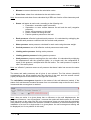
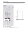
B.4.2.3. CHADEISSON curves
The Chadeisson curves were published in a paper by A. Monnet, “Module de réaction,
coefficient de décompression, au sujet des paramètres utilisés dans la méthode de calcul
élasto-plastique”, published in Revue Française de Géotechnique n° 65 [5].
The curves are displayed and the proper value is retrieved automatically depending on the
values input for the cohesion and the friction angle. It is also possible to check those values
directly on the curves.
Figure B 23: Chadeisson curves
Note: The curves have been reproduced approximately. There may be a slight difference
between the curves that appear in the wizard window and the Chadeisson curves that can be
found in papers.
Copyright © K-REA – TERRASOL 2004 - April 2008
37/58
B – User manual K-REA
B.4.3. EI and Rc wizard
This wizard helps to estimate EI and Rc values, for three different types of walls: diaphragm
walls (circular or not), piles and sheet-piles. The wizard can be reached from the retaining
wall dialogue box (Data, Retaining wall).
Specific parameters should be entered for each type of wall. EI estimations are displayed in
blue.
The dialogue box is closed automatically when the values are transferred using the transfer
button
close it.
. Otherwise, click the X button located in the title bar of the window to
B.4.3.1. Diaphragm walls
This wizard enables to calculate the EI product as well as the cylindrical rigidity Rc for a
continuous wall.
Figure B 24: Calculation of the EI product for a diaphragm wall
Three values should be defined:
• E: concrete Young’s modulus (it can be chosen from the listbox) (MPa, kPa, t/m2);
• e: wall thickness (m);
• Rc: radius of the circular wall when the wall is circular (MN/m3, kN/m3, t/m3).
These values can be transfered to the main dialogue box by using the Transfer button. Click
Quit and Save to close the wizard.
Note: the rigidity values are given per linear meter. It is necessary to correct them if the
elementary wall width is not equal to 1 m (refer to chapter 3.3).
The software calculates:
38/58
EI = Econcrete *
1* e3
Ee
et Rc = 2
12
R
for L=1 m
April 2008 - Copyright © K-REA – TERRASOL 2004
B – User manual K-REA
B.4.3.2. Spaced or jointed piles
This wizard enables to calculate the EI product (given per linear meter) for spaced or jointed
piles. These piles can be made of concrete, steel or a combination of both materials.
Select “circular piles (spaced or jointed)” as shown on the screenshot below:
Figure B 25: Calculation of the EI product for a circular pile
Three values should be defined:
• E: concrete Young’s modulus (MPa, kPa, t/m2);
• eh: spacing between piles (m);
• d: piles diameter (m).
The software calculates
EI =
Copyright © K-REA – TERRASOL 2004 - April 2008
πd4
64eh
Econcrete
39/58
B – User manual K-REA
In order to calculate the EI product for steel piles, select “Circular piles (spaced or jointed)”,
then “steel sections", as shown below:
Figure B 26: calculation of the EI product for steel circular piles
You should select a type of steel section. Use the “steel section” listbox to choose among the
following categories:
•
•
Specific steel section: enables to set an inertia that is not available in the list;
Hollow circular steel section: enables to calculate the inertia of hollow circular
sections, using their external diameter and their thickness;
• IPE, IPE A, IPE O: I-shaped European ARCELOR beams;
• IPN: normal European ARCELOR beams;
• HE AA, HE A, HE B, HE M: European wide wings ARCELOR beams;
• HL: European very wide wings ARCELOR beams;
• HD: ARCELOR column-beams;
• HP: ARCELOR pile-beams;
• TUBEUROP diameter/thickness: hollow and circular TUBEUROP sections;
• TUBES STAD diameter/thickness: hollow and circular TUBES STAD sections.
*This list of suppliers is not exhaustive.
Input the complementary requested data when needed, and do not forget to define the
spacing between sections axis.
The software calculates
EI =
I steel
Esteel
eh
Note: use the Transfer >> button.
40/58
April 2008 - Copyright © K-REA – TERRASOL 2004
B – User manual K-REA
In order to calculate the inertia of a pile made of both steel and concrete, click “Circular piles
(spaced or jointed)” then “steel sections” as shown thereafter:
Figure B 27: Calculation of the EI product for mixed walls
Fill in both the steel section parameters and the concrete parameters.
The software calculates:
EI =
πd4
64eh
Econcrete +
I sec tion
I
Esec tion − sec tion Econcrete
eh
eh
This formula applies to different section geometries:
+
-
+
=
-
=
Note 1: use the Transfer >> button.
Note 2: the rigidity values are given per linear meter. It is necessary to correct them if the
elementary wall width is not equal to 1 m (refer to chapter 3.3).
Copyright © K-REA – TERRASOL 2004 - April 2008
41/58
B – User manual K-REA
B.4.3.3. Sheet-pile walls
This wizard enables to calculate the product of inertia of sheet-pile walls (given per linear
meter), taking corrosion into account.
Figure B 28: Sheet-piles database
Two values should be defined:
• E: concrete Young’s modulus (MPa, kPa, t/m2);
• I: inertia of the sheet-piles in 104 mm4 (a database may be used).
Note: the rigidity values are given per linear meter. It is necessary to correct them if the
elementary wall width is not equal to 1 m (refer to chapter 3.3).
42/58
April 2008 - Copyright © K-REA – TERRASOL 2004
B – User manual K-REA
B.5. Staged construction
When the soil and the wall properties have been defined, the staged construction must be
described.
Each phase can include one or several actions. It is fully up to the user to decide and define
the actions for each phase, but be aware that the staged construction management can have
an influence on the results, due to the interactions between different actions. In order to
make sure that the actions combinations are correct, refer to part C of the manual (Technical
manual), and check the properties for each action.
By default, K-REA always creates a first phase named “Initial phase” as illustrated on the
figure below:
Action
selection
zone
Action parameters zone
Staged construction management zone
Figure B 29: Initial phase
In this first phase, three actions are available. They can be applied only in this phase and
only once. Those are the actions: “Caquot surcharge” (uniformly distributed on both sides of
the wall), “Reduced pressure” and “Maximal pressure”. The use of the action selection zone
is described in the chapter B2.3.2. and the meaning of the actions is given in the part C –
Technical manual. If actions are applied in the initial phase, they will be displayed on the
graphical representation of the staged construction management zone after their validation.
In order to create Phase 1, click on the
button in the staged construction
management zone. This action creates a new tab named “Phase 1” and the schematic profile
Copyright © K-REA – TERRASOL 2004 - April 2008
43/58
B – User manual K-REA
of the soil layers remains the same. But after each validation of an action, the profile of the
project is modified to take into account this action.
Figure B 30: Phase 1
Each time new phases will be added, corresponding tabs will appear next to the existing
tabs. The tabs of the staged construction management zone allow an easy and quick
browsing between the calculation phases of the project by a simple click on each tab.
The handling of the action selection and action parameters zones, in order to define the
actions for a phase, are described in chapters B.2.3.2 et B.2.3.3. respectively. The whole
actions are detailed individually in part C – Technical manual.
44/58
April 2008 - Copyright © K-REA – TERRASOL 2004
B – User manual K-REA
B.6. Calculation and results
B.6.1. Calculation
In K-REA, there are three different ways to run the calculation:
•
Click on the shortcut button
•
Click on the calculation button
•
Or select the Calculation/Results menu and then Calculation.
located in the action selection zone;
in the buttons bar;
The calculation can be performed at any time (in the initial phase, in the current phase, in the
final phase), as long as all the data for the soil layers and for the wall have been fully defined.
It enables to obtain the values of displacements, moments and shear forces in the wall, or
else the values of the pressures in the soil on both sides of the wall, etc.
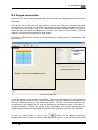
B.6.2. Results
After the calculation, the curves for displacements, shear forces and moments appear in the
staged construction management zone, in the current phase tab.
It is possible to view additional curves and tables when opening the results window.
The results window is a separate window, using the same tab-navigation system as the main
window.
There are three ways to open this window:
•
click on the button
•
click on the shortcut button
•
or select Calculation/Results and then the Results sub-menu.
in the action selection zone;
in the buttons bar;
In the results window, a warning appears in case the calculation did not converge (which
means that the maximal number of iterations defined in the general options of the project
was reached).
Copyright © K-REA – TERRASOL 2004 - April 2008
45/58
B – User manual K-REA
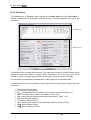
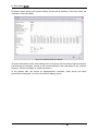
By default, when opening the results window, the first tab is activated. This is the “Data” tab
(reminder of the input data):
Figure B 31: Results window, Data tab
This tab summarises all the data relating to the soil layers, the wall and the selected options
(like buckling for example), as well as the actions defined for the initial phase if any (reduced
pressure, Caquot surcharge or maximal pressure).
In the phases tabs, the curves for displacements, moments, shear forces and earth
pressures are displayed (“curves” is the default display option).
46/58
April 2008 - Copyright © K-REA – TERRASOL 2004
B – User manual K-REA
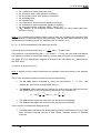
The phases tabs are divided into five zones:
I
V
II
III
IV
Figure B 32: Graphical results display for phase 2
Zone I. The first zone is the display selection zone. It enables to shift between curves and
tables.
Zone II. The second zone is devoted to the curves display:
•
the displacements displayed in millimeters ;
•
the moments displayed in the units system chosen for the project;
•
the shear forces displayed the units system chosen for the project;
•
the earth and water pressures, red curves for the earth pressures and blue dotted
curves for the water pressures. Negative pressures are those applied onto the left
side of the wall (downhill side), and positive pressures are those applied onto the
right side of the wall (uphill side).
The minimal and maximal values for each curve are displayed below the curves.
Zone III. The third zone is located in the lower left corner of the window, and contains two
listboxes:
•
The first list includes the actions defined for the current phase and their parameters. It
also indicates the convergence status of the calculation for this phase.
•
The second list displays the longitudinal forces in the anchors for the current phase. If
the anchors wizard was used to define the project, the forces and the maximal
resistance for each anchor will also be displayed.
Zone IV. If the option “Display ratio limiting/mobilised earth resistance” was checked in the
project settings, this ratio is displayed in this zone.
Copyright © K-REA – TERRASOL 2004 - April 2008
47/58
B – User manual K-REA
Zone V. This zone is dedicated to warning messages. Such messages appear when the
calculation did not converge, when an anchor works in compression, or when a strut works in
traction (if the convention “main excavation on downhill side”, i.e. on the left to the wall, is
respected).
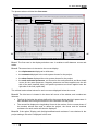
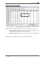
When the “tables” display option is checked, only zone II changes, as shown below:
II
Figure B 33: Tables for results of phase 5
The title bar on top of the table includes information about the columns (results type, side of
the wall (downhill or uphill, units system).
A thorough description of the columns is given hereafter:
•
Depth or level: position of calculation points (nodes) along the wall, in depths or in
levels (depending on the choice for the project). The calculation step is the maximal
distance between two nodes. But the distance between two nodes can be smaller
than that, because the program includes nodes at the interfaces between soil layers
and at the anchors heads (1 node for each anchor and 2 nodes for each soil
interface).
•
Rotation: rotation for the structure at the calculation node, when forces are
equilibrated.
•
Displacement: displacement of the structure at the calculation node, when forces are
equilibrated.
Note: the rotation is positive from uphill to downhill and displacements are positive from
downhill to uphill.
48/58
April 2008 - Copyright © K-REA – TERRASOL 2004
B – User manual K-REA
•
Moment: moment calculated at the calculation nodes.
•
Shear force: shear force calculated at the calculation nodes.
Note: the moments and shear forces calculated by K-REA are function of the elementary wall
width.
•
Status: soil status at each node, according to the following rule:
• Excavation: excavation uphill or downhill;
• Separation: no more contact between the soil and the wall (=negative
pressure);
• Active: active pressure on the wall;
• Elastic: elastic soil facing the wall;
• Passive: passive pressure on the wall.
•
Earth pressure: effective horizontal earth pressure. It is calculated by multiplying the
relevant earth pressure coefficient with the vertical earth pressure.
•
Water pressure: water pressure calculated for each node using the water weight.
•
Vertical pressure: sum of all effective vertical pressures at each node.
•
Limiting active pressure: limiting active pressure.
•
Limiting passive pressure: limiting passive pressure.
•
Vault pressure: pressure resulting from the vault effect. It is calculated by multiplying
the displacement with the cylindrical rigidity. In a circular wall, the compression is
equal to this pressure, multiplied with the wall radius. The vault pressure is equal to
zero if the wall is plane.
Note: an “effective” pressure means a soil pressure that doesn’t take into account the water
pressure.
The status and earth pressures are all given in two columns. The first column (downhill)
corresponds to the forces applied onto the left side of the wall, and the second column
(uphill) corresponds to the forces onto the right side of the wall.
The calculation convergence depends on the status of the wall elements (nodes). If the
status of all wall elements remains the same from one calculation step to the next one, then it
is assumed that convergence is reached.
Note: when an action in a given phase has no influence on the wall displacements, the
program will detect a “non-convergence”, because the results will be the same for all nodes
from one phase to the other. But this “non-convergence” does not mean that the calculation
really failed to converge within the maximum number of iterations (a common example is the
installation of a strut as a single action in a given phase: the non-convergence warning will
be displayed, but it’s no problem in this case).
Copyright © K-REA – TERRASOL 2004 - April 2008
49/58
B – User manual K-REA
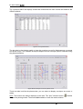
The “synthesis table” tab displays a table that summarises the main results calculated for the
different phases:
Figure B 34: Synthesis table
The last tabs in the window enable to view the envelope curves for displacements, moments
and shear forces. The available envelopes depend on the envelope options selected during
the phases definition:
Figure B 35: Envelope curves for phases 1 to 5
These last tabs look like the phases tabs: you can select to display envelopes as curves or
tables.
Note: Two buttons are always displayed in the tabs. The “print” shortcut button
to open the printing wizard. The button Quit enables to close the results window.
50/58
enables
April 2008 - Copyright © K-REA – TERRASOL 2004
B – User manual K-REA
B.7. Display options
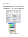
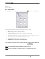
B.7.1. Layers colours
This wizard can be opened by selecting the Wizard menu and then Layers colours. The soil
layers dialogue box appears. Double-click on the colour to be modified, in order to open the
colours wizard.
This wizard enables to change the default colour assigned to each soil layer. These new
colours will be considered as the new default settings for all projects with K-REA.
Figure B 36: Colour wizard for the soil layers
Copyright © K-REA – TERRASOL 2004 - April 2008
51/58
B – User manual K-REA
B.7.2. Popup menus
These menus are not permanently displayed in the main window of K-REA. They can be
displayed by a right-click on some K-REA objects.
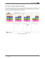
B.7.2.1. Popup dialogue box for the graphical display settings in the main window
This dialogue box appears after a right-click on the graphical representation in the main
window.
Figure B 37: Popup dialogue box for the graphical display in the main window
It enables to change the display settings: display of the levels of the soil layers interfaces, of
the anchors, surcharges, excavations, fills, etc. on the graphical representation of the project.
It also enables to display the values of the surcharges or the names of the soil layers.
The listbox in the upper part of this dialogue box enables to select which display setting you
want to change. The radiobuttons available in the dialogue box depend on this choice.
Here are examples of this dialogue box:
Figure B 38: Additional examples of the popup dialogue box
Use the radio buttons to define your new display settings, and click on Validate and Quit.
The new settings will be taken into account on the graphical representation, and the dialogue
box will be closed automatically.
52/58
April 2008 - Copyright © K-REA – TERRASOL 2004
B – User manual K-REA
B.7.2.2. Popup menu in the synthesis tables
This menu appears when the synthesis tables for the soil layers or the wall are right-clicked.
Figure B 39: Right-click menu in the soil layers table
Here are the available options:
•
Copy K-REA selection: copies the selected values (one line for example) into
the clipboard.
•
Paste K-REA selection: pastes the copied values into the table.
•
Copy to clipboard: copies the synthesis table to clipboard, so that it can be later
pasted into another document.
•
Insert line: creates an empty line above the selected line.
•
Delete one or several line(s): deletes the selected line(s).
•
Initialize table: erases all values in the table.
•
Adjust columns width: optimizes the columns width.
B.7.2.3. Popup menu in the results window
Each table or curve in the results window can be right-clicked to display this popup menu.
Example: popup menu on a results curve
Left-click on a curve to select it.
Right-click on the same curve to display the popup menu. The following options are
available:
•
Copy: enables to copy the curve to the clipboard.
•
Curves format: enables to change the curve settings (line thickness, line style).
Copyright © K-REA – TERRASOL 2004 - April 2008
53/58
B – User manual K-REA
•
Background colour: enables to change the background colour of the curve.
Modification of the curve settings,
and copy into a Word document.
Figure B 40: Popup menu on the curves
54/58
April 2008 - Copyright © K-REA – TERRASOL 2004
B – User manual K-REA
Example: popup menu on a results table
Figure B 41: Popup menu on a results table
Right-click on the table to display the popup menu. The following options are available:
•
Copy to clipboard: enables to copy the selected table to the clipboard, so that it
can be pasted into another document (Excel, Word, etc…).
•
Adjust column width: enables to reduce the columns width as much as possible.
All these popup menus enable to customize your results display in K-REA.
Copyright © K-REA – TERRASOL 2004 - April 2008
55/58
B – User manual K-REA
B.8. Printing
B.8.1. Printing wizard
The printing wizard can be opened with the shortcut button
or with the menu File, Print.
Figure B 42: Printing wizard
The printing wizard enables to select which elements should be printed:
•
Data: prints the first tab of the results window.
•
Graphical synthesis: prints the phases synthesis (see next page).
•
Results per phase: prints the output for the selected phases. All phases can also be
selected at once. It is possible to edit tables and/or curves.
•
Results synthesis: prints the results synthesis.
•
Envelopes: prints the envelope curves and/or tables.
These elements can be copied into the clipboard (rather than printed), in order to paste them
later into another document. In that case, click on the button
.
Note 1: the results window must be opened before printing the curves.
Note 2: the tables to be copied to the clipboard have to be selected using the mouse.
56/58
April 2008 - Copyright © K-REA – TERRASOL 2004
B – User manual K-REA
B.8.2. Phases synthesis (graphical synthesis)
This command enables to print or copy a graphical synthesis of the project to the clipboard. It
includes the schematic representation of the project for each phase, as well as the list of
actions selected for each phase and their parameters.
Figure B 43: Phases synthesis
Copyright © K-REA – TERRASOL 2004 - April 2008
57/58
B – User manual K-REA
BIBLIOGRAPHY
[1] J. Kérisel and E. Absi. Tables de pression et de butée des terres. Presses de l’Ecole
Nationale des Ponts et Chaussée, last edited in 2003.
[2] F. Schlosser. Ouvrages de soutènement, pression et butée. Techniques de l’ingénieur ;
Construction ; C242.
[3] J. Balay. Recommandations pour le choix des paramètres de calcul des écrans de
soutènement par la méthode aux modules de réaction. Note d’information technique, LCPC,
1984.
[4] P. Schmitt. Méthode empirique d’évaluation du coefficient de réaction du sol vis-à-vis des
ouvrages de soutènement souple. Revue Française de Géotechnique n° 71, 2nd trimester
1995.
[5] A. Monnet. Module de réaction, coefficient de décompression, au sujet des paramètres
utilisés dans la méthode de calcul élasto-plastique des soutènements. Revue Française de
Géotechnique n° 65, 1st trimester 1994.
[6] Review n°62. LCPC-SETRA.
58/58
April 2008 - Copyright © K-REA – TERRASOL 2004