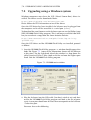
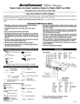
1
S M A R T AV I O N I C S PB-2 Propeller Balancer User Manual $Revision: 278 $ Copyright 2003-2012 Smart Avionics Limited. All rights reserved. Polar Wizard is not a registered trademark of Smart Avionics Ltd. Smart Avionics Limited reserves the right to change or improve its products at any time without obligation to upgrade or modify existing products. Unless indicated otherwise, the contents of this document apply to any revision of the product’s software. Document Revision History Revision 278 Date December 2011 Author MB 258 February 2010 MB 215 190 June 2008 February 2008 MB MB Remarks Added description of SPECTRUM WINDOW TYPE parameter Updated the section describing upgrading the firmware using a Windows system Add description of multi-page spectrum display Initial version (based on PB-1 manual) Contents 1 Introduction 1 1.1 Minimising other sources of vibration . . . . . . . . . . . . . 2 1.2 Propeller mass imbalance . . . . . . . . . . . . . . . . . . . 2 1.3 Static propeller balancing . . . . . . . . . . . . . . . . . . . 3 1.4 Dynamic propeller balancing . . . . . . . . . . . . . . . . . 4 2 Balancer Features 7 2.1 Battery charging . . . . . . . . . . . . . . . . . . . . . . . . 8 2.2 Power switch . . . . . . . . . . . . . . . . . . . . . . . . . . 8 2.3 Keypad . . . . . . . . . . . . . . . . . . . . . . . . . . . . . . 9 2.4 LCD Display . . . . . . . . . . . . . . . . . . . . . . . . . . . 10 2.5 Balancer Parameters . . . . . . . . . . . . . . . . . . . . . . 10 2.5.1 Job parameters . . . . . . . . . . . . . . . . . . . . . 10 2.5.2 System parameters . . . . . . . . . . . . . . . . . . . 13 3 Balancer Mode 15 3.1 Graphical display . . . . . . . . . . . . . . . . . . . . . . . . 15 3.2 Textual Information . . . . . . . . . . . . . . . . . . . . . . 18 3.3 Snapshots and the result history . . . . . . . . . . . . . . . . 19 4 Preparing for Dynamic Balancing 21 4.1 Additional items required . . . . . . . . . . . . . . . . . . . 21 4.2 Positioning the aircraft . . . . . . . . . . . . . . . . . . . . . 21 4.3 Mounting the accelerometer . . . . . . . . . . . . . . . . . . 22 4.4 Mounting the optical sensor . . . . . . . . . . . . . . . . . . 24 4.5 Attaching the reflective tape . . . . . . . . . . . . . . . . . . 27 4.6 Attaching the cables . . . . . . . . . . . . . . . . . . . . . . 28 4.7 Pre-balancing actions . . . . . . . . . . . . . . . . . . . . . . 29 i CONTENTS ii 5 Using the Balancer 31 5.1 Adjusting the display contrast . . . . . . . . . . . . . . . . . 31 5.2 Adjusting the optical sensor threshold level . . . . . . . . . 31 5.3 Taking a balance reading . . . . . . . . . . . . . . . . . . . . 32 5.4 Attaching balance weights . . . . . . . . . . . . . . . . . . . 33 5.5 Using the Polar Wizard . . . . . . . . . . . . . . . . . . . . . 33 5.6 Using the polar chart . . . . . . . . . . . . . . . . . . . . . . 35 5.7 After balancing . . . . . . . . . . . . . . . . . . . . . . . . . 37 5.8 Troubleshooting . . . . . . . . . . . . . . . . . . . . . . . . . 37 5.8.1 The screen is very dark or completely black . . . . . 37 5.8.2 The displayed RPM is erratic or wrong . . . . . . . . 37 5.8.3 The displayed angle error value is high . . . . . . . . 38 5.8.4 Adding weight does not reduce the vibration level . . 39 6 Spectrum Analyser Mode 41 6.1 Graphical spectrum plot . . . . . . . . . . . . . . . . . . . . 42 6.2 Spectrum peaks display . . . . . . . . . . . . . . . . . . . . 43 6.3 Limitations of spectrum mode . . . . . . . . . . . . . . . . . 43 6.4 Using spectrum mode without the optical sensor . . . . . . . 44 7 Upgrading the Balancer’s Firmware 45 7.1 Upgrading using a Linux system . . . . . . . . . . . . . . . . 45 7.2 Upgrading using a Windows system . . . . . . . . . . . . . . 47 A Software Licenses A.1 KISS FFT Library . . . . . . . . . . . . . . . . . . . . . . . . B Conformity B.1 EMC Compliance . . . . . . . . . . . . . . . . . . . . . . . . 49 49 51 51 C CE Declaration of Conformity 53 D Polar Chart 55 List of Figures 1.1 Idealised accelerometer output . . . . . . . . . . . . . . . . 4 2.1 Front view of the balancer . . . . . . . . . . . . . . . . . . . 7 2.2 Side view of the balancer . . . . . . . . . . . . . . . . . . . 8 3.1 XY plot of ideal vibration waveform . . . . . . . . . . . . . . 16 3.2 Polar plot of ideal vibration waveform . . . . . . . . . . . . 16 3.3 Polar average plot of ideal vibration waveform . . . . . . . . 17 3.4 Polar average display with text . . . . . . . . . . . . . . . . 18 4.1 Accelerometer orientation . . . . . . . . . . . . . . . . . . . 22 4.2 Accelerometer mounted on rear of Rotax 912 gearbox . . . 23 4.3 Optical sensor orientation . . . . . . . . . . . . . . . . . . . 25 4.4 Optical sensor angle of incidence . . . . . . . . . . . . . . . 26 4.5 Optical sensor mounting . . . . . . . . . . . . . . . . . . . . 26 4.6 Optical sensor and reflective tape . . . . . . . . . . . . . . . 28 4.7 Taping cable to cowling . . . . . . . . . . . . . . . . . . . . 28 5.1 Example plot on polar chart . . . . . . . . . . . . . . . . . . 36 6.1 Spectrum plot showing 4 components . . . . . . . . . . . . 42 6.2 Peaks display showing 4 components . . . . . . . . . . . . . 43 7.1 LPC2000 main window . . . . . . . . . . . . . . . . . . . . . 47 iii List of Tables 1.1 FAA vibration limits . . . . . . . . . . . . . . . . . . . . . . . 3 2.1 Optimal cycles for various PSRU ratios . . . . . . . . . . . . 11 v Chapter 1 Introduction This manual describes how to use the Smart Avionics PB-2 Propeller Balancer1 to dynamically balance an aircraft propeller so as to minimise the level of vibration caused by propeller/spinner mass imbalance. The balancer provides two major modes of operation; balancer mode and spectrum mode. Balancer mode is used to balance a propeller. Spectrum mode can be used as a general purpose diagnostic aid to help solve vibration related problems. The primary function of the balancer is to measure and report the level of propeller vibration along with an indication of where weight should be added to counteract the imbalance. Although the balancer is principally designed for use with propellers fitted to homebuilt and experimental aircraft, it should be effective in balancing any propeller. The balancer is not difficult to use. To ensure you get the best results, please read all of this manual before trying to use the balancer. If you have any questions, please send email to [email protected]. ! Caution Propellers can kill. Make sure that the ignition is switched off before touching the propeller. Always assume that the engine could fire when the propeller is being moved. Make sure that the aircraft is securely chocked or tied down while carrying out the balancing process. 1 Hereafter referred to as ‘the balancer’. 1 CHAPTER 1. INTRODUCTION 2 1.1 Minimising other sources of vibration Propeller mass imbalance can be a major source of vibration. However, there are other sources of vibration as well. To minimise the overall vibration level and to make the dynamic balancing process more effective, all other sources of vibration must be minimised before the dynamic balancing process is carried out. ! Important Unless the engine is running smoothly, there is little point in trying to balance the propeller. Carburettor imbalance, dirty plugs, loose engine mounts and general wear and tear are just some of the reasons why the engine could be producing excess vibration. Propellers with an adjustable blade pitch will produce a lot of vibration if all of the blades are not set to the same pitch. This is critical: if a blade’s pitch differs from its neighbours by even a fraction of a degree, it will produce vibration that appears to be caused by mass imbalance but cannot actually be removed by mass balancing. ! Important Before attempting to dynamically balance a variable pitch propeller2 , confirm that the blades’ pitch are equal to within the tolerance specified by the propeller’s manufacturer (typically, 0.25◦ ). For maximum accuracy, the dynamic balancing process should only be carried out in light winds. Ideally, the wind should be less than 5 kts. The aircraft should be positioned so that it is pointing into any wind. 1.2 Propeller mass imbalance A major source of propeller vibration is propeller mass imbalance. When an object rotates around an axis, if the mass of the object is not uniformly distributed around that axis, a force (the centripetal force) will be generated and will cause vibration3 . As the magnitude of the force is proportional to the square of the rotational velocity, at high RPMs (high rotational velocity) 2 Either ground adjustable or in-flight adjustable. The centripetal force is equal to mv 2 /r where m is the mass of the rotating body, r is the distance of the body’s centre of mass from the axis of rotation and v is the tangential velocity. 3 1.3. STATIC PROPELLER BALANCING 3 even a small mass imbalance in a propeller will generate an appreciable amount of force (and hence vibration). This vibration can be measured by mounting a sensor on the engine as close to the propeller as possible. Conventionally, the magnitude of a propeller’s vibration is reported as a peak velocity4 in units of Inches Per Second (IPS). The FAA have assigned the following descriptions to velocity levels: Table 1.1: FAA vibration limits Peak Velocity ≥ 1.25 IPS Summary Danger ≥ 1.0 IPS Very Rough ≥ 0.5 IPS Rough ≥ 0.25 IPS Slightly Rough ≥ 0.15 IPS Fair ≥ 0.07 IPS Good 1.3 Description Propeller should be removed and a static balance performed. Propeller can be dynamically balanced but a large amount of corrective weight will be required. Operation at this vibration level could cause damage. Propeller definitely requires dynamic balancing. Long term operation at this level could cause excessive wear. Dynamic balance will improve passenger comfort. This is the maximum acceptable level after dynamic balancing. Vibration levels less than this will not be detected by pilot or passengers. Static propeller balancing A propeller can be statically balanced in the workshop using a static balancing tool. This often involves suspending the propeller from its central axis. If the propeller is (statically) balanced, the blades should be level5 . If one blade is heavier than the others (or its centre of mass is further from the centre of the propeller), it will dip towards the floor. If this occurs, weight can be added to the hub on the opposite side of the central axis to the dipping blade to bring the propeller level. All propellers should be manufactured with blades that have equal mass (and mass distribution) and so a new propeller should not require static 4 The sensor can either measure velocity directly or measure the acceleration which is integrated to yield the velocity. 5 The propeller will be statically balanced when the mass of each blade multiplied by the distance from the blade’s centre of mass to the centre of the propeller is the same for all of the blades. CHAPTER 1. INTRODUCTION 4 balancing. Propellers that have suffered damage to the blades (stone chips or tip abrasion) may well benefit from being statically balanced. While statically balancing a propeller is worthwhile, the best results will be obtained if the propeller is dynamically balanced together with the spinner. 1.4 Dynamic propeller balancing Dynamic propeller balancing involves measuring the actual rotational vibration generated at a realistic propeller RPM and then adding weights to the propeller hub or spinner backplate to minimise the measured vibration level. Because the balancing operation is carried out with the propeller and spinner attached to the engine, the best possible solution is obtained. The vibration is measured using a sensor known as an accelerometer. The accelerometer is securely attached to the engine as close to the propeller as possible and it measures the acceleration of the front of the engine in one direction (normal to the propeller shaft). If the propeller is out of balance, as the centre of mass rotates around the axis of rotation, the resulting centripetal force tries to pull the propeller (along with the spinner and engine) towards the centre of mass. This rotating imbalance force acts on the mass of the engine/propeller combination and accelerates it. It is this acceleration that is measured by the accelerometer. Figure 1.1: Idealised accelerometer output +ve 0 −ve If the accelerometer was very selective and measured only the vibration caused by the rotating out-of-balance propeller, the signal it produced for one rotation of the propeller would look like a sine wave as shown in Figure 1.1. In reality, the measured acceleration waveform is much more complex than a simple sine wave. This is mainly because of the vibration generated by the engine and also the turbulence generated by the rotating propeller blades. The dynamics of the engine mountings also affect the waveform. The balancer’s processing unit digitises the measured acceleration wave- 1.4. DYNAMIC PROPELLER BALANCING 5 form and uses the resulting numbers to calculate the magnitude of the vibration signal. This magnitude is reported as a peak velocity in units of Inches Per Second (IPS). The accelerometer senses the magnitude of the vibration but more information is required to carry out the balancing process. This is because it is not sufficient to know just the magnitude of the vibration signal. It is also necessary to know the phase of that signal. The phase of the signal is the relationship of the signal waveform to the angular position of the propeller. Given the phase information, it is possible to determine where the weight is required to be added to reduce the vibration. By detecting when one particular propeller blade passes an optical sensor, the balancer can measure and report the phase of the vibration waveform. The optical sensor also works as a tachometer to measure the propeller RPM. 6 CHAPTER 1. INTRODUCTION Chapter 2 Balancer Features Figure 2.1 shows a front view of the main balancer unit. On the top face are the keypad and graphical (LCD) display. Figure 2.1: Front view of the balancer On the left side of the unit (shown in Figure 2.2 on the following page) 7 CHAPTER 2. BALANCER FEATURES 8 Figure 2.2: Side view of the balancer are (from left to right) the charging connector, the connector for the accelerometer cable, a USB socket1 and the connector for the optical sensor cable. 2.1 Battery charging The balancer’s battery is charged via the charging connector on the left hand side using the supplied 9V adapter (universal input 110-240V). • The centre pin of the connector is positive. • Only charge the battery when the temperature is greater than -15◦ C (5◦ F) and less than 50◦ C (122◦ F) • It takes approximately 12 hours to recharge a completely flat battery. • The adapter may be left connected indefinitely without overcharging the battery. • When the battery is fully charged, it should operate the balancer for at least 8 hours before it requires charging again. • If you are not going to use the balancer for some time (months), please charge the battery fully before storing the balancer as this will extend the battery life. 2.2 Power switch The power switch is a low-profile circular button located on the top edge of the unit. To switch the power on, hold the button until the ‘PB-2’ banner appears. You can then let go of the button. To switch the power off, hold the power button until the ‘OFF’ banner appears. The unit will automatically power down after 3 minutes (duration configurable) if no keys have been pressed. 1 The USB socket is used to connect the balancer to a PC so that the firmware can be updated. 2.3. KEYPAD 2.3 9 Keypad The keypad is used to control the balancer’s operation. The following keys are provided: F1 F2 F3 F4 – Function keys The functions assigned to these keys vary depending on the current mode. In all balancer and spectrum modes, F1 takes you to the parameter editing screens as described in Section 2.5 on the next page. < – Select previous item Pressing < will select the previous item in the current list of items. For example, when editing the balancer’s parameters it selects the previous parameter. - – Decrement value - has two uses: 1. In any of the balancer or spectrum mode screens, - will reduce the contrast of the LCD screen (make it lighter). 2. When editing parameters, the value of the currently selected parameter is decremented by pressing - . Holding the key down will auto-repeat. + – Increment value + has two uses: 1. In any of the balancer or spectrum mode screens, + will increase the contrast of the LCD screen (make it darker). 2. When editing parameters, the value of the currently selected parameter is incremented by pressing + . Holding the key down will auto-repeat. > – Select next item Pressing > will select the next item in the current list of items. For example, when editing the balancer’s parameters it selects the next parameter. BM – Select balancer mode Pressing BM cycles through the balancer modes (XY plot, polar plot, polar average). When the key is held down, the help screen for the next mode is displayed (until the key is released). Chapter 3 (Balancer Mode) describes the balancer modes. CHAPTER 2. BALANCER FEATURES 10 SM – Select spectrum analyser mode Pressing SM cycles through the spectrum analyser modes (spectrum plot, spectrum peaks). When the key is held down, the help screen for the next mode is displayed (until the key is released). Chapter 6 (Spectrum Analyser Mode) describes the spectrum analyser modes. ? – Show help Pressing the ? key displays a help screen for the current mode. The help screen describes briefly the current mode and lists the keys that can be used. Pressing any key will return to the previous screen. * – Take a snapshot When the balancer is in polar average mode, the * key takes a ‘snapshot’ of the current vibration results. See Section 3.3 on page 19 for more information about snapshots and the result history display. 2.4 LCD Display The LCD display is a combined text and graphics display. The display is easily readable in strong sunlight as long as the viewing angle is not too large. The contrast of the display does vary with ambient temperature so you may need to occasionally adjust the contrast using + and - . 2.5 Balancer Parameters A small number of parameters that modify the balancer’s behaviour can be changed. Pressing F1 in balancer or spectrum modes brings you to the parameter editing screens. The parameters are split into two groups; job and system. The values of the job parameters are likely to be changed on a per-job basis. The system parameters are very rarely changed (if at all). When in parameter editing mode, pressing F1 will toggle between the two groups of parameters. < and > cycle through the parameters in each group. - and + adjust the value of the currently selected parameter. * exits parameter editing mode. 2.5.1 Job parameters TACHO LEVEL Can be set to 1, 2, 3, ... 255. 2.5. BALANCER PARAMETERS 11 The default value is 75. This parameter adjusts the threshold level for the optical tachometer. To obtain the best results, it must be adjusted correctly as described in Section 5.2 on page 31. To help you do this, the current RPM is displayed every second. Note From any balancer or spectrum mode, pressing F4 invokes an auto-set function that automatically determines a suitable value for TACHO LEVEL by quickly scanning through the levels while monitoring the RPM. CYCLES Can be set to ‘PSRU 1.82’, ‘PSRU 2.12’, ‘PSRU 2.27’, ‘PSRU 2.43’, ‘AUTO’, 1, 2, 3, . . . 127. The default value is AUTO. This parameter specifies the number of propeller cycles (revolutions) over which the acceleration waveform will be averaged for each update of the display. A value of AUTO specifies that the number of cycles to be averaged is automatically determined from the current RPM (the higher the current RPM value, the more cycles will be averaged.) The number of cycles chosen will be one of 1, 2, 4, 8, 16 or 32. By increasing the number of cycles averaged, better results are obtained because the effect of any random vibration signals picked up on each revolution of the propeller are reduced. On the other hand, as the number of cycles averaged increases, the update rate of the display is reduced and this becomes particularly noticeable at low RPMs. To stop the display update rate becoming too low, the number of cycles to average is automatically reduced at low RPMs. If you wish to obtain the best possible results at low RPMs (< 500) and you can accept a low display update rate, manually increase the value of this parameter. For 4-stroke engines fitted with a PSRU, the optimum number of cycles to use is dependent on the ratio of propeller to engine speed. Table 2.1 lists the PSRU ratios known to the balancer. Just use the - and + keys to select the required PSRU ratio. The pre-programmed values are ‘below’ AUTO. Table 2.1: Optimal cycles for various PSRU ratios PSRU Ratio 1.82 2.12 2.27 2.43 Cycles 11 17 15 14 Engine Type Eggenfellner Subaru NSI Subaru Rotax 912 Rotax 912S & 914 CHAPTER 2. BALANCER FEATURES 12 If the table doesn’t show a value for your engine, you can work out a value to use as follows: for any given gearbox ratio, CYCLES is optimal if CYCLES × RATIO / 2 is an integer (whole) number. The closer the result is to an integer value, the better. For example, if the gearbox ratio was 2.35, half the gearbox ratio would be 1.175 and the multiples of that are 1.175 (×1), 2.35 (×2), ... 7.05 (×6), ..., 19.975 (×17). Using a value of 6 would give acceptable results with a reasonable update rate, using 17 would give slightly better results but at less than half the update rate. So in this case, 6 is the best value to use. If in doubt, please contact Smart Avionics for help. FILTER Can be set to ‘AUTO’, 0, 1, 2, 3, ... 127. The default value is AUTO. This parameter specifies the width of the filter used to remove high frequency components from the digitised acceleration waveform. A value of AUTO specifies that the filter width is automatically determined from the number of samples captured. The value of this parameter does have an effect on the reported IPS value because the wider the filter width, the more the acceleration waveform is smoothed which will reduce the reported IPS value. STEADY RPM MARGIN Can be set to 0, 1, 2, 3, . . . 255. The default value is 5. The maximum amount the RPM is allowed to change when taking a snapshot. It is specified as a percentage. If set to 0, the RPM is not checked for steadiness. SPECTRUM WINDOW TYPE Can be set to ‘NONE’, ‘HANN’ or ‘FLAT TOP’. The default value is ‘HANN’. The type of window function that is applied to the spectrum input data: None No window function is used so the display will show artifacts due to the ‘spectral leakage’ that occurs when aperiodic waveforms are processed by a discrete Fourier transform. Hann The Hann window function reduces the spectral leakage and produces a display with fewer artifacts and better frequency resolution. Flat Top The Flat Top window function reduces the spectral leakage and produces the most accurate magnitudes. 2.5. BALANCER PARAMETERS 13 Note As the parameters retain their values when the balancer is switched off, each time the balancer is switched on, a warning screen is displayed if the CYCLES or FILTER WIDTH parameters are set to a nondefault value. This is to remind you that you may wish to change their values if you are starting a new job. 2.5.2 System parameters Think twice before changing any of these parameters! AUTO OFF Can be set to 0, 1, 2, 3, . . . 99. The default value is 3. This is the duration of the idle timeout in minutes. If no keys are pressed for this amount of time, the unit switches itself off to avoid wasting battery power. Setting the value to 0, disables the timeout completely. ACCELEROMETER ADC COUNTS/G Can be set to 1, 2, 3, . . . 1023. The default value is 273. This parameter scales the accelerometer output. It is specified as Analog to Digital Converter (ADC) counts per G of acceleration. You should not need to radically alter it unless you use a different kind of accelerometer. However, you can adjust the value by small amounts to calibrate the accelerometer. If you want to do this, follow these steps: 1. Connect the accelerometer to the main unit. 2. Turn the main unit on and then press F1 twice to get to the system parameter editing screens. 3. Locate the ACCELEROMETER COUNTS/G parameter. You will see that the current ADC value is shown along with the acceleration value that it is converted to. Orientate the accelerometer so that the connector is pointing straight up or straight down and note the current ADC reading. 4. Re-orientate the accelerometer so that the connector is pointing in the opposite direction and note the new reading2 . 2 Note that the accelerometer output is ‘biased’ so the displayed G values will not be ±1 as you might expect. CHAPTER 2. BALANCER FEATURES 14 5. Subtract the smaller reading from the larger reading and divide the result by 2 to obtain the optimal value for the ACCELEROMETER COUNTS/G parameter. It should not be much different from the default value of 273. If it is greatly different, do not use the balancer and contact Smart Avionics for assistance. TACHO DIV Can be set to 0, 1, 2, 3, . . . 255. The default value is 0. This is the number of tachometer pulses per propeller revolution. When using the Smart Avionics optical sensor, this value must be 0. TACHO SHORT PULSES REQ Can be set to 1, 2, 3, . . . 255. The default value is 3. A magic parameter that modifies the behaviour of the optical tachometer. Normally, you should not need to change this value. It is possible that for some propellers that are both very shiny and have very curved rear surfaces, increasing the value of this parameter will help to obtain a steady RPM reading. Chapter 3 Balancer Mode The main function of the balancer is accessed using balancer mode. Specifically, the polar average sub-mode is the mode you will use when balancing a propeller. The other two sub-modes, XY plot and polar plot are much less important but they do provide a graphical means of viewing the vibration information that can be useful when diagnosing vibration problems. 3.1 Graphical display When using balancer mode, the vibration waveform is shown on the balancer’s LCD display. The visual style of the display is dependent on the selected sub-mode. Pressing BM cycles through the sub-modes which are: XY plot This sub-mode shows the vibration waveform for one propeller revolution as an XY plot. The X (horizontal) axis is time and the Y (vertical) axis the acceleration. The left hand side of the display corresponds to when the optical sensor has just detected the primary (taped) blade. The height of the waveform is automatically adjusted to fill most of the screen. The XY plot of the sine wave vibration waveform shown in Figure 1.1 on page 4 would look like Figure 3.1 on the following page. 15 CHAPTER 3. BALANCER MODE 16 Figure 3.1: XY plot of ideal vibration waveform Yes, it just looks like a sine wave! Note Visually interpreting the raw acceleration data shown in the XY plot is not always easy but the time-domain information it presents can be useful when investigating vibration problems. It can be used alongside spectrum mode (described in Chapter 6 (Spectrum Analyser Mode)) that provides a frequency-domain display of the vibration. Polar plot This sub-mode shows the vibration waveform for one propeller revolution as a polar plot. The time axis is circular around the centre of the screen (rather than left to right as in XY plot mode). The acceleration is zero in the centre of the plot. The waveform starts at the 12 o’clock position and is plotted clockwise. As with XY plot mode, the size of the plotted waveform is automatically adjusted to make best use of the screen. The polar plot of the sine wave vibration waveform shown in Figure 1.1 on page 4 would look like Figure 3.2. Figure 3.2: Polar plot of ideal vibration waveform 3.1. GRAPHICAL DISPLAY 17 The average position of the plotted points is also displayed as a small + symbol. This point is called the ‘polar average’. The position of the polar average point gives a good visual indication of the phase of the vibration waveform, i.e. as the phase of the waveform changes, the polar average point will rotate around the centre of the screen. You may wonder why the plot doesn’t look like a figure of 8 with two lobes instead of one. It is because one lobe lies on top of the other owing to the fact they are 180◦ out of phase and have opposite polarity. When a ’real’ vibration waveform is displayed, the differences between the positive and negative halves of the acceleration waveform make the two lobes different shapes and so one half does not exactly match the other. Polar average Unlike the other two sub-modes, this sub-mode does not display the raw vibration waveform. Instead, it displays the polar average using the + symbol and a running average of the polar average coordinates. This ‘polar average average’ point is displayed as a symbol and, to make it more obvious, a line from the centre of the screen to the is drawn. This line provides a visual indication of the averaged phase of the vibration waveform. The polar average plot of the sine wave vibration waveform shown in Figure 1.1 on page 4 would look like Figure 3.3. Figure 3.3: Polar average plot of ideal vibration waveform As with the other sub-modes, the display is automatically scaled so the length of the line is not an indication of the magnitude of the vibration. The magnitude is reported as text (described below). Due to the averaging, the information shown in polar average mode does not vary so quickly as the other balancer modes and so it is easier to interpret visually. It should be remembered that real vibration waveforms are much ‘noisier’ than the idealised waveforms shown above. This is especially true when CHAPTER 3. BALANCER MODE 18 the propeller is nearly balanced because the magnitude of the imbalance waveform becomes small compared to the noise. 3.2 Textual Information In addition to the graphics described above, the LCD display also provides textual information as shown in Figure 3.4. Figure 3.4: Polar average display with text RPM 1845 65 DEG 0.10 IPS BAT 60% ERR 3 GOOD From top to bottom, left to right, the following information is displayed: RPM The RPM of the propeller as detected by the optical sensor. For engines with gearboxes (i.e. Rotax engines), the propeller RPM will be a fraction of the engine RPM. Please consult your engine documentation to determine the gearbox ratio. Battery Level The charge level of the balancer’s battery, shown as a percentage (099). Please note that the battery level display over-reads while the battery is being charged. Phase Angle (only displayed in polar average mode) The phase angle of the vibration waveform is displayed as a number in the range 0 to 359. This value is smoothed by averaging over a number of propeller cycles. Angle Error (only displayed in polar average mode) This calculated error value1 is displayed as a number between 0 and 1 It’s actually the Standard Deviation of the phase angle. 3.3. SNAPSHOTS AND THE RESULT HISTORY 19 99. Low values (say < 30) indicate that the measured phase angle is consistent and, therefore, relatively trustworthy. High values (> 60) indicate that the measured phase angle is varying greatly and it should not be considered so trustworthy. Generally, as the balance of the propeller is improved, the displayed angle error will increase as the vibration caused by mass imbalance becomes a smaller fraction of the overall level of vibration. Vibration Magnitude The magnitude of the vibration in IPS (Inches Per Second). This value is smoothed by averaging over a number of propeller cycles. Description of Magnitude The summary of the current vibration magnitude from Table 1.1 on page 3. To save screen space, - and + are used as prefixes and they have the same meaning as in a TAF or METAR. For example, -ROUGH means ‘slightly rough’ and +ROUGH means ‘very rough’. 3.3 Snapshots and the result history Pressing * when in polar average mode and with the engine running will take a snapshot of the current vibration data (IPS, RPM, DEG, ERR) and store the values in the result history which is then displayed. Keep * pressed until either the screen changes to show the result history or WAIT is displayed. While the snapshot is being taken, the RPM must not vary too much. If it does, the display will momentarily show RPM NOT STEADY and the snapshot process will be restarted. If the RPM continues to be unsteady, the snapshot will be abandoned after a few seconds. If the engine is not running, pressing * will display the result history without taking a new snapshot. The result history screen shows the last 5 snapshots, the most recent snapshot being at the top of the screen. Here is an example result history screen with 3 snapshots: RESULT HISTORY IPS RPM DEG ER --------------->.10 1306 143 8 .10 1300 144 6 .11 1310 140 10 [F1] [F2] [F3] [F4] [<][>] [*] = = = = = = START CLEAR DEL SOLVE MOVE QUIT CHAPTER 3. BALANCER MODE 20 As you can see, it provides a summary of vibration magnitude (IPS), propeller RPM (RPM), phase angle (DEG) and angle error (ER). The current snapshot is indicated by ‘>’ in the leftmost column. When showing the result history, these keys can be used: F1 – Set start point Selects the current snapshot as the start point to be used by the Polar Wizard (The Polar Wizard is described in Section 5.5 on page 33). F2 – Clear all snapshots Holding this key for about a second clears all of the snapshots from the result history. F3 – Deletes current snapshot Holding this key for about a second deletes the current snapshot. F4 – Solves for the current snapshot Invokes the Polar Wizard to calculate a solution from the current snapshot and the previously selected start point (The Polar Wizard is described in Section 5.5 on page 33). < > – Move between snapshots Moves the ‘>’ up and down the list of snapshots. * Quit result history and return to polar average mode. The contents of the result history are preserved when the balancer is switched off. Chapter 4 Preparing for Dynamic Balancing 4.1 Additional items required To carry out the balancing process, you will need the following items in addition to the balancer kit: • Balance weights (typically AN970 washers) and a means of securely attaching them to the spinner backplate. • A scale for measuring the weights is useful but not absolutely essential as the balancer works in terms of relative weight rather than absolute weight. • If necessary, a bracket for mounting the accelerometer onto the front of the engine (optional, depending on engine type and installation details). A M6 screw and washer are supplied which can be used to attach the accelerometer to the back of a Rotax 4-stroke gearbox if the vacuum pump option is not fitted. 4.2 Positioning the aircraft The following points should be observed regarding positioning the aircraft for a propeller balancing session: 1. The position must be safe for ground running of the engine. Typically, the engine will need to be run at cruise RPM and the aircraft should be braked and chocked and, if necessary, tied down. 2. Considering where it is intended to locate the optical sensor, the position of the aircraft should be such that direct sunlight will not fall onto the sensor’s red window. If the sun is low on the horizon it is best if the sun does not fall within the arc of the propeller when viewed from the location of the optical sensor. The optical sensor can be mounted on any side of the cowling. 21 22 CHAPTER 4. PREPARING FOR DYNAMIC BALANCING 3. If the wind is appreciable (> 5kts), point the aircraft as close into wind as possible while observing point 2 above. 4.3 Mounting the accelerometer Remove sufficient cowlings to gain access to the front of the engine. Mount the accelerometer (40mm square with a 6mm hole through the middle) as near to the front of the engine as possible with the cable socket pointing away from the propeller’s centre line. The accelerometer’s sensing axis is parallel with the direction of the cable socket and this sensing axis should intersect the axis of rotation of the propeller. Figure 4.1 shows this graphically. Note that the accelerometer does not have to be directly above the propeller’s axis of rotation. However, to get the best results you should not mount the accelerometer such that the sensing axis is parallel with the engine’s cylinders. For example, on a Rotax 912 don’t mount the accelerometer to the side of the propeller centre line; instead, mount the accelerometer either above or below the centre line. On a Rotax 912 that doesn’t have a vacuum pump attached, the best place to mount the accelerometer is on the rear of the gearbox using one of the available tapped holes and the supplied M6 screw and washer. Figure 4.2 on the facing page shows the accelerometer mounted on the rear of a Rotax 912 gearbox. Figure 4.1: Accelerometer orientation 4.3. MOUNTING THE ACCELEROMETER 23 Figure 4.2: Accelerometer mounted on rear of Rotax 912 gearbox If the accelerometer cannot be mounted directly on the engine, some form of bracket will be required. Obviously, the details of this are engine specific but it could be as simple as a strip of metal with a hole drilled at each end. If a bracket is used, it must be sufficiently stiff to ensure that the accelerometer does not move with respect to the engine. However the accelerometer is mounted, it must not be subjected to excessive temperatures. The temperature of the sensor should not exceed 85◦ C. If necessary, thermally insulating material can be sandwiched between the accelerometer and the engine (or bracket) to reduce the amount of heat conducted to the accelerometer. If the surrounding area will be very hot, the accelerometer could be wrapped in thermally insulating material (once the cable has been attached). ! Important It is essential that the accelerometer is firmly attached to the front of the engine with the cable socket pointing away from the propeller centre line. If a mounting bracket is used, it must be stiff enough not to flex appreciably. Do not attach the accelerometer directly to a part of the engine that gets very hot. If necessary, use thermally insulating material between the sensor and the engine. The accelerometer is robust but may be damaged if dropped on a hard surface. CHAPTER 4. PREPARING FOR DYNAMIC BALANCING 24 It is preferable to refit the engine cowling to minimise the turbulence generated by the airflow from the propeller. For some aircraft, the cowling will have to be refitted to provide a suitable mounting position for the optical sensor. However, if the balance weights are to be added to the rear of the spinner backplate, it may pay to leave the cowling off (if possible) during the balancing process so that it is easier to gain access to the weights. Once the balancing has been completed, the cowling could be replaced and a final reading taken to determine the level of vibration achieved. 4.4 Mounting the optical sensor It is important that the optical sensor (65mm square with a red window at one end) is mounted in a suitable position to ensure reliable operation. Owing to the variation in aircraft cowling shapes and sizes, only generic instructions can be provided here. You may find that a little experimentation is required to obtain the best results. A square of flexible plastic is supplied that is attached to the sensor using Velcro tape. This square can easily be taped to the outside cowling using masking tape. If necessary, extra tape can be used to help keep the sensor attached to the cowling. Position the optical sensor such that the red window is pointing towards the propeller and the cable socket is pointing away from the propeller. If the sensor’s orientation is correct, the blades will sweep across the width of the red window as the propeller rotates. The distance from the front of the sensor to the propeller is not especially critical but should be about 20–25cm. Figure 4.3 on the next page illustrates how the sensor could be positioned on the side of a cowling so that the blades sweep across the sensor’s red window. ! Caution When the balancer is switched on, the optical sensor emits infra-red light from the red window in a narrow, concentrated, beam. This invisible light could irritate or otherwise damage the human eye if viewed directly at close range. Do not look directly into the red window when the balancer is switched on. 4.4. MOUNTING THE OPTICAL SENSOR 25 Figure 4.3: Optical sensor orientation ! Important To detect the propeller RPM reliably, the sensor must be positioned such that the angle of the sensor’s infrared beam relative to the face of the propeller blade is approximately 25◦ from the normal (either in front of or behind the normal). Figure 4.4 on the following page illustrates this. If the angle is too small, the sensor will tend to detect the other blades (especially if they are highly reflective) and the RPM will be erratically too high. If the angle is too large, the blade with the reflective tape will not be reliably detected and the RPM will be zero or erratically too low. Figure 4.5 on the next page shows the optical sensor mounted on the side of a Europa classic cowling. Notice how it is angled down to ensure that the angle of the infrared beam relative to the rear surface of the propeller is approximately 25◦ . 26 CHAPTER 4. PREPARING FOR DYNAMIC BALANCING Figure 4.4: Optical sensor angle of incidence Approx 25 degrees angle of incidence (from normal) Normal Optical Sensor Figure 4.5: Optical sensor mounting 4.5. ATTACHING THE REFLECTIVE TAPE 4.5 27 Attaching the reflective tape With the engine ignition switched off, rotate the propeller1 so that one blade lies directly on the sensing axis of the optical sensor, i.e. if you could see through the blade you would be looking directly into the sensor’s red window. Make sure that the area where the tape is going to be attached is clean. Apply a strip of 25mm wide masking tape to the face of the propeller at the point that the sensor’s infrared beam will hit the blade. Wrap the tape a short distance around the leading edge of the blade but don’t wrap it around the trailing edge. ! Important The tape must be oriented such that it is parallel to the sensor’s red window. This may mean that the tape is not at 90◦ to the leading edge of the blade but that doesn’t matter. The important point is that the tape is parallel with the red window. Now put a strip of the reflective tape on top of the masking tape. Again, wrap the tape a little way around the leading edge of the propeller to stop it peeling back. The purpose of the masking tape is simply to make it easy to remove the (very thin) reflecting tape when the job is done. Figure 4.6 on the following page shows the optical sensor mounted on the side of a Europa classic cowling and the reflective tape attached to the rear face of a propeller blade. 1 Some engines must only be rotated by hand in the forward direction. 28 CHAPTER 4. PREPARING FOR DYNAMIC BALANCING Figure 4.6: Optical sensor and reflective tape 4.6 Attaching the cables Connect the sensors to the main unit using the supplied cables and make sure the connectors’ retaining collars are screwed down (finger tight is sufficient). The two cables are identical but the connectors are arranged such that it is not possible to connect the sensors the wrong way around. A few strategically placed pieces of masking tape will stop the cables flapping around in the propeller breeze. If you tape the cables as shown in Figure 4.7, they are unlikely to come adrift. Figure 4.7: Taping cable to cowling Cowling Cable Tape 4.7. PRE-BALANCING ACTIONS ! 29 Important To obtain the best results, the cables to the sensors should be kept away from sources of electrical interference such as ignition leads, magnetos/ignition units, generators/altenators/regulators and their associated wiring. Be especially careful to ensure that the cables cannot get close to rotating components or very hot surfaces or get pinched by the aircraft door if being led into the cockpit. 4.7 Pre-balancing actions Before taking any readings: 1. Remove any existing weights attached to hub/spinner/spinner backplate. Do not remove weights that were added when the propeller was statically balanced. 2. Check that the value of the CYCLES parameter is correct for the engine type as described in Page 11. The balancer remembers the last value of CYCLES that was set when switched off. 30 CHAPTER 4. PREPARING FOR DYNAMIC BALANCING Chapter 5 Using the Balancer ! Important It is the operator’s responsibility to ensure that any procedures or guidelines that have been issued by the manufacturers of the propeller, engine or aircraft or some other agency (e.g. the FAA/CAA/LAA/BMAA), that specify how the propeller is to be balanced, are adhered to. The following instructions describe the balancing process from the point of view of operating the balancer and determining where balance weights are to be attached. The exact detail of how balance weights are attached to the hub or spinner backplate is beyond the scope of this document. If you have any doubt, please consult your inspector/engineer. 5.1 Adjusting the display contrast As the LCD display’s contrast varies with ambient temperature, you may need to adjust it using + or - to get the best display. 5.2 Adjusting the optical sensor threshold level Run the engine and check that the displayed RPM is consistent with the engine RPM. If the engine is fitted with a gearbox, remember to take into account the gearbox ratio when comparing the RPM values. If the balancer displays an incorrect RPM (it could be zero or much too high or fluctuating a lot), then it is likely that the TACHO LEVEL parameter needs adjusting. This is most easily done by pressing F4 to invoke an auto-set function that scans through the levels while monitoring the detected RPM. 31 CHAPTER 5. USING THE BALANCER 32 When it has finished, hit any key to return to the balancer mode. You can also adjust TACHO LEVEL manually using the parameter editor (accessed through F1 ). If the RPM cannot be detected reliably at any setting of the threshold level, see Section 5.8.2 on page 37 for a list of possible reasons1. If the displayed RPM is too large, it likely that the sensor is detecting multiple blades per revolution and either the sensor must be moved further away or the angle of incidence of the infrared beam to the reflective tape must be increased. If the RPM is too small (or zero), either the sensor should either be moved closer to the propeller or the angle of incidence of the infrared beam must be reduced. Check that the reflective tape is passing directly through the axis of the beam and that the tape is parallel to the sensor’s red window. Also check that the sun is not directly shining into the red window2 . Once the RPM is being reliably detected, you are ready to start the balancing process. 5.3 Taking a balance reading To take a reading: 1. Run the engine at the chosen RPM. To get the best results, it is important to choose a speed that minimises the error value displayed in polar average mode. To do this, start at approximately 1000 RPM and increase the speed noting the RPM that shows the lowest average error value. As the extraneous vibration generated by the engine and the airflow increases with RPM, it’s best to use the lowest RPM that shows a low error value. Once you have determined the best RPM to use, it is important to use the same RPM for each balancing run so that you get consistent results. 2. With a steady RPM being reported by the balancer and the display in polar average mode, press and hold * until WAIT is displayed on the screen. This will take a snapshot of the currently displayed values and show you the result history (see Section 3.3 on page 19 for more detail on snapshots and the result history). Pressing * again will return you to the polar average display. Take a few snapshots and check that they show reasonably consistent results. If the propeller is out of balance, the IPS value will be high and the angle error low. 1 As the battery level drops, TACHO LEVEL will need to be reduced to compensate for the reduced level of IR transmitted by the optical sensor. 2 Ideally, the sun should not be in such a position that, when viewed from the position of the sensor, the sun is ‘chopped’ by the propeller blades. 5.4. ATTACHING BALANCE WEIGHTS 33 Once the reading has been taken, stop the engine and double-check that the ignition is switched off. If the vibration level is already 0.15 IPS or less, the propeller can be considered reasonably well balanced3 . If you wish to improve the balance, you must add weight. Section 5.5 describes how to use the Polar Wizard to determine the position and amount of weight to be added. Alternatively, Section 5.6 on page 35 explains how to use a polar chart to do the same job. Note Even if you only use the Polar Wizard, it’s worth reading the section on using the polar chart as it will help your understanding of the balancing process. Once you have used the balancer a few times, you will recognise from the dynamics of the polar average graphical display how well balanced the propeller is. An out-of-balance propeller produces a relatively steady display: the polar average indicator (the + symbol) does move around but will stay reasonably close to the polar average average point (the symbol); the (and the line to the centre of the display) will be relatively static. If the propeller is well balanced, the + will move around wildly and the will jump about also. If the angle error estimate is consistently high (> 60), it indicates that a large proportion of the vibration is being caused by something other than propeller imbalance and there is no point in carrying on the balancing process until the level of non-propeller vibration has been reduced. 5.4 Attaching balance weights Having checked the ignition is switched off, securely attach the required weight using an approved method as close as possible to the desired position. If the weight attachment points available do not allow you to add the weight at the desired position, it may be possible to attach two smaller weights either side of that position such that their combined influence is equal to the influence required. 5.5 Using the Polar Wizard This section describes how the position and the mass of the balance weight is determined using the Polar Wizard. Simply follow these steps: 3 In ideal conditions, the balancer is capable of balancing a propeller down to about 0.03 IPS so you may wish to continue the process to achieve a better result. CHAPTER 5. USING THE BALANCER 34 1. With no balance weights attached to the propeller4 , take one or more snapshots. Looking at the result history, select one of the snapshots to be the start point by pressing F1 . 2. Assuming that the reported IPS value is sufficient to want to continue the balancing process, securely attach a ‘trial weight’. The angular position of the weight is not important at this stage. For a typical composite propeller, a few AN970 washers would be a reasonable initial trial weight. 3. Take one or more snapshots with the trial weight in place and invoke the Polar Wizard on a selected snapshot (the current point) by pressing F4 . Using the start point and the current point, the Wizard will calculate the influence of the trial weight and determine where the weight has to be moved to and how much the weight needs to be scaled to minimise the vibration. Here is an example screen: Result: GOOD Start point was 0.21 IPS 129 DEG Current point is 0.10 IPS 143 DEG Move the weight back 12 deg Increase weight to 1.85 times what it is now [*] = QUIT From top to bottom, it reports the quality of the balance with the trial weight in the current position, the details of the start and current points, the amount the weight should be moved (in degrees) to improve the balance and the amount the weight must be scaled by to improve the balance. Directions are in terms of propeller rotation, forward means in the direction of rotation and backwards means opposite to the direction of rotation. 4. Following the directions shown in the above screen, the weight is moved back and increased and a new snapshot is taken. This time the Polar Wizard reports: Result: +GOOD Start point was 0.21 IPS 129 DEG Current point is 0.03 IPS 164 DEG Position OK Amount OK [*] = QUIT 4 Apart from any weights that were added during static balancing. 5.6. USING THE POLAR CHART 35 The position of the weight is reported as OK as it is within 5 degrees of the optimal position and the amount of weight is reported as OK as it is within 5% of the optimal amount. When balancing a real propeller you will probably have to adjust the weight a couple of times to get the best result. The Polar Wizard doesn’t explicitly state that the propeller is well balanced, it’s up to the operator to decide when to stop the process based on the vibration magnitude (IPS) achieved. As long as the IPS is deemed sufficiently low, it doesn’t really matter if the Polar Wizard says that the weight position or amount needs changing5 . If the Polar Wizard reports ‘No solution!’ then it means that the start and current points are very close together. This could be because the trial weight is not large enough to have much influence or that extraneous vibration is masking any propeller imbalance. 5.6 Using the polar chart This section describes how the position and the mass of the balance weight is determined using a polar chart. Appendix D (Polar Chart) contains a polar chart that you may copy and use during balancing. A laminated copy of this chart is provided with the balancer. Plotting a result obtained using the balancer on the chart is straightforward. Simply mark the chart with a dot or a cross at the point that corresponds to the reported angle and IPS readings. To determine the position of the balance weight using the polar chart, follow these instructions: 1. With no balance weights attached to the propeller6 , take a reading with the balancer and plot the result on the chart. Label it as point 0. Draw a line from point 0 to the centre of the chart (we will call this line the imbalance vector). 2. Assuming that the reported IPS value is sufficient to want to continue the balancing process, securely attach a ‘trial weight’. The angular position of the weight is not important at this stage. For a typical composite propeller, a few AN970 washers would be a reasonable initial trial weight. 3. Take another reading and plot that as point 1. If points 1 and 0 are very close together on the polar chart, the trial weight needs to be increased so add a couple more washers and plot the result of another reading. If you are still not seeing any significant separation between point 0 and the latest point on the chart, perhaps the vibration is not being caused 5 6 The Wizard is very demanding! Apart from any weights that were added during static balancing. CHAPTER 5. USING THE BALANCER 36 by mass imbalance. If that’s the case, stop balancing and check for pitch imbalance or mechanical problems. If the propeller is very heavy or the trial weight is close to the centre of rotation, you may simply have not added enough weight yet. Assuming that adding the trial weight has moved point 1 away from point 0, draw a line between those two points (this line is called the correction vector). Now measure the angle between the imbalance vector and the correction vector. When the propeller is balanced, this angle will be as small as possible (ideally, zero). If the angle is not yet sufficiently small, the balance can be improved by moving the trial weight around the hub/spinner by the same angle. To determine the direction the weight must move, orientate the chart such that point 0 is below the centre (the imbalance vector is vertical). If the correction vector is to the right of the imbalance vector, the trial weight must be moved in the direction of propeller rotation. Conversely, if the correction vector is to the left of the imbalance vector, the trial weight must be moved in the direction opposite to propeller rotation. Figure 5.1 shows how the points and vectors can be drawn. Figure 5.1: Example plot on polar chart 0 345 15 30 330 45 315 60 300 75 285 0.1 270 ce an 255 l ba Im or ct e v rre Co 0.2 0.4 Point 1 or ect v n ctio 105 120 240 Point 0 225 0.6 90 In this example, the weight must be moved in the direction of rotation by135 this angle to improve the balance 150 210 165 195 180 5.7. AFTER BALANCING 37 4. Move the trial weight to the new position, take a new reading and plot this as point 2. Draw a new correction vector (from point 0 to point 2). The angle between the imbalance vector and the new correction vector should now be very small. If not, repeat the process using the new correction vector instead of the last one. Repeat this step as necessary. 5. Once the direction of the vectors is closely aligned, all that remains to do is to tune the amount of weight so that the vector lengths become the same. When they are the same length, the propeller is balanced and the IPS reading should be very low. Compare the lengths of the vectors and adjust the weight accordingly. If the imbalance vector is longer than the correction vector, you need to increase the weight and vice-versa The amount the weight has to change is proportional to the relative lengths of the vectors e.g. if the imbalance vector is twice as long as the correction vector, the weight must be doubled. 5.7 After balancing When the balancing has been completed, double-check that all balance weights are securely attached. If you have been using temporary weights to carry out the balancing, they should be replaced with permanent weights whose mass and position are such that they have the same effect as the temporary weights. If in doubt, recheck the balance once the permanent weights are installed. Remove the sensors and the tape from the propeller blade. Make an entry in the appropriate log book to record the vibration level achieved and the RPM used. 5.8 Troubleshooting This section provides answers to common problems that can arise when using the balancer. 5.8.1 The screen is very dark or completely black The contrast is incorrectly adjusted or the balancer has been allowed to become very hot which makes the LCD go black (it will return to normal when it cools). 5.8.2 The displayed RPM is erratic or wrong The RPM could be unsteady for the following reasons (most likely first): CHAPTER 5. USING THE BALANCER 38 • The optical sensor threshold level (TACHO LEVEL parameter) needs adjusting. • The optical sensor is not pointing at the reflective tape or the tape is not parallel with the sensor’s window. • The sun is shining directly into the optical sensor’s window or being ‘chopped’ by the propeller. • The optical sensor is either too close (< 15cm) or too far away (> 30cm) from the propeller. • The angle of incidence of the infrared beam on the propeller blade is outside the acceptable range (15 – 40◦ ). • The sensor is being confused by extra reflections from metal propeller blades. Try adding non-reflective tape to the other blades in the same position as the reflective tape. • The engine RPM really is changing! 5.8.3 The displayed angle error value is high This indicates that the vibration waveform is not consistent from one propeller revolution to the next. This implies that some (perhaps most) of the measured vibration is out of phase with the propeller. If the reported vibration magnitude is more than 0.15 IPS, it is likely that some other source of vibration (rather than propeller mass or pitch imbalance) is having an effect. Any of the following problems will increase the angle error: • The CYCLES parameter is not set to the optimal value for the type of engine (see Table 2.1 on page 11). • The RPM is not being reliably detected (see previous section). Unless the RPM is correct, the angle and error values are meaningless. • You are using an RPM at which the engine doesn’t run smoothly. • You are using an RPM that is triggering an airframe resonance. • The accelerometer is not securely mounted or its sensing axis is not pointing at the propeller’s axis of rotation or the sensing axis is parallel with the direction of movement of the engine’s pistons. • The spinner is wobbling. • The engine is not running correctly or the engine mounts are in poor condition. • The engine cowling is not fitted to minimise the effects of turbulence. • The wind is gusting. 5.8. TROUBLESHOOTING 39 5.8.4 Adding weight does not reduce the vibration level If the balancer reports a significant level of vibration with a low angle error and adding weight doesn’t appear to reduce the level or substantially change the angle, any of the following could be true: • The CYCLES parameter is not set to the optimal value for the type of engine (see Table 2.1 on page 11). • The propeller is suffering from pitch imbalance (the blades don’t have equal pitch). Pitch imbalance has to be corrected before the propeller can be dynamically balanced. • The amount of weight being added is too small to have an effect. The heavier the propeller/spinner, the more weight has to be added to reduce a given level of vibration. • The weight is not being added at the correct position. Double check your points, lines and angle on the polar chart. 40 CHAPTER 5. USING THE BALANCER Chapter 6 Spectrum Analyser Mode The balancer features a basic spectrum analyser capability that is useful for carrying out cabin vibration surveys and general vibration troubleshooting. This mode does not need to be used to balance a propeller. However, if during balancing a large amount of vibration is observed and that vibration is not caused by propeller mass imbalance, then use of spectrum mode may provide an indication as to where the vibration is coming from. For example, if the spectrum analysis shows that there is an excessive amount of vibration at a frequency that is half of the engine RPM, that can indicate that one of the engine’s cylinders is lacking in power (or that the engine mounts are not in good shape). A full discussion of the interpretation of vibration spectra is beyond the scope of this document. How does spectrum mode work? Mathematically, the vibration waveform is constructed from a set of pure sine waves (each with a different frequency, phase and magnitude). Generally speaking, the more complex the waveform is, the more components it has. In spectrum mode, the vibration waveform is analysed to determine the magnitude and frequency of each of the waveform’s components and that information is displayed either graphically or as a list of numbers1 . The operator can therefore determine how much vibration is present at the various frequencies of interest (propeller RPM, crankshaft RPM, blade pass frequency and so on). If this sounds rather complicated, don’t panic because spectrum mode is very easy to use. Spectrum mode is selected by pressing SM . Further presses of SM cycles between the two spectrum sub-modes; spectrum plot and spectrum peaks. While in spectrum mode, the balancer continuously samples the vibration waveform, calculates the magnitudes of the spectrum’s components and then displays the magnitudes either graphically or as a list of peak IPS values. Pressing * will pause the display. Pressing * again will un-pause the display. While the display is paused, the * character on the screen flashes 1 The components’ phase is not used by the balancer. 41 42 CHAPTER 6. SPECTRUM ANALYSER MODE to remind the operator that the display is not being updated. If spectrum mode is paused, the data will be remembered even if the unit powers down. 6.1 Graphical spectrum plot The spectrum is plotted as a sequence of vertical lines. Each line represents the magnitude of an individual frequency component. Frequency increases from left to right in multiples of 100 RPM. The spectrum display is split into two pages; the first page shows the spectrum from 100 to 12700 RPM and the second page shows the spectrum from 12800 to 25500 RPM. Pressing F2 toggles between the pages. A dotted vertical cursor line is displayed. The magnitude and frequency of the component corresponding to the cursor line’s position are reported. Also reported are the current propeller RPM, the battery state and the ratio of the cursor line RPM to the actual propeller RPM. This last item is useful as peaks in the spectrum often occur at multiples of the propeller RPM and this feature makes it easy to identify them. Figure 6.1 shows an idealised graphical display of a spectrum containing 4 components. This is typical of the spectrum you could see when looking at a 3 bladed propeller on an engine that has a step-down gearbox. Figure 6.1: Spectrum plot showing 4 components RPM 1845 BAT 60% IPS RPM xPROP 0.15 1800 0.98 [*] = PAUSE The cursor line is positioned at the component that corresponds to the propeller RPM and, as expected, the ratio of cursor RPM to propeller RPM is (close to) 1. The line on the far right is at blade pass frequency (3 × propeller RPM), second from right is at the crankshaft frequency and the remaining line is at the half crankshaft frequency. If the optical sensor is operating, the cursor line’s horizontal position will be 6.2. SPECTRUM PEAKS DISPLAY 43 automatically altered to track the propeller RPM. Alternatively, the position of the cursor line can be manually adjusted using the < and > keys. The longer these keys are held down, the faster the cursor line will move. If the cursor is moved off the edge of the current page, the other page will be displayed. Manually moving the cursor line or displaying the other half of the spectrum (using F2 ) disables the tracking of the propeller RPM. Pressing F3 will return the unit to tracking the propeller RPM. 6.2 Spectrum peaks display This extremely useful display mode lists the magnitudes and frequencies (RPM) of the largest components in the vibration waveform. Figure 6.2 shows the peaks display. Figure 6.2: Peaks display showing 4 components RPM 1845 IPS 0.15 0.12 0.09 0.07 BAT 60% RPM xPROP 1800 0.98 5400 2.93 4200 2.28 2100 1.14 [*] = PAUSE Up to 8 components are listed and they are ordered by decreasing magnitude. In this example, four components are listed and they correspond to propeller RPM, blade pass frequency, crankshaft RPM and half crankshaft RPM. 6.3 Limitations of spectrum mode In reality2 , a waveform’s spectrum is continuous rather than discrete and the frequencies of the waveform’s components are not constrained to be multiples of 100 RPM. A consequence of the discrete nature of the analysis is that the magnitude of any component can be spread across neighbouring 2 If a mathematical concept can be said to be ‘real’. 44 CHAPTER 6. SPECTRUM ANALYSER MODE lines in the spectrum. At the present time, the balancer’s software does not merge the magnitudes of neighbouring components to compensate for this effect. How does this affect the results? When the results are displayed graphically, the operator can see how the spectral lines change height as the frequencies of the components alter. If the component RPM is very close to a multiple of 100, a single line will be shown. As the RPM moves away from a multiple of 100, the height of the line diminishes and the neighbouring line grows. In the worst case, a line may be half its correct height (along with a neighbouring line of almost the same height). Of course, as the magnitudes and the frequencies are constantly varying anyway, the displayed spectrum is always going to be changing unless the display is paused. When the components are displayed as a list, only the peaks are listed and the magnitudes of the neighbouring components are not shown. Be aware that, in the worst case, the reported value for a component’s magnitude could be nearly half of the component’s real magnitude. You can always check by toggling to the graphical plot and seeing if the peak is standing alone or if it has neighbours of a similar height. 6.4 Using spectrum mode without the optical sensor Spectrum mode can be used without the optical sensor. The only differences are that the propeller RPM is not measured and so the ratio of propeller RPM to the RPM of the components cannot be shown (the right hand column is blank) and the cursor line cannot track the propeller RPM. To use spectrum mode without the optical sensor, simply disconnect the cable to the optical sensor at the main unit end. When used in this way, the accelerometer does not have to be mounted on the engine but it can be held against anything that you wish to measure the vibration of. Remember that the sensing axis of the accelerometer is parallel to the cable socket. A particularly good use of spectrum mode without the optical sensor is for carrying out cabin vibration surveys. This can be done on the ground but best results will be obtained if it is done in flight. A reading can be taken by simply holding the vibration sensor firmly against a hard surface in the cabin and pressing * to capture the current values. Chapter 7 Upgrading the Balancer’s Firmware The balancer’s firmware can be upgraded via the USB connector. In general terms, the upgrade process involves connecting the balancer to your computer using a standard USB cable and then running a utility program on the computer to download the new firmware to the balancer. Exactly how this is achieved is dependent on the system running on your PC. The new balancer firmware will be named pb2-version.hex, where version is the firmware version number. 7.1 Upgrading using a Linux system If you are using a modern Linux system, upgrading the firmware is easily done using the third-party lpc21isp utility program that is available from the Smart Avionics website – follow these steps: 1. Download the new firmware file and the lpc21isp program from the Smart Avionics website and save them in a convenient directory. 2. Open a command shell and cd to the directory containing the saved files. 3. When you connect the balancer it will appear as a new USB serial device. We need to access that device by name. Linux systems generally name the USB serial devices with names like /dev/ttyUSBx where the x is a number1 . Before you plug the USB cable into the balancer, execute the following command to list the names of any USB serial devices already present: ls /dev/ttyUSB* 1 Linux systems do vary in their naming of USB serial devices so if you can’t find the new device when it is plugged in, please contact Smart Avionics for assistance. 45 46 CHAPTER 7. UPGRADING THE BALANCER’S FIRMWARE You will either see a list of names or, if no USB serial devices are presently connected to your system, ls will gripe because the wildcard (*) didn’t match anything. 4. Now plug the balancer into the USB cable (but do not turn the balancer on) and list the USB serial devices again. You should now see a new name along with any others that were listed before2 . To send the firmware to the balancer execute: ./lpc21isp -control pb2-version.hex /dev/ttyUSBx 38400 10000 Where pb2-version.hex is the name of the file containing the new firmware and /dev/ttyUSBx is the name of the serial device corresponding to the balancer. The lpc21isp program should display diagnostic output like the following example (the lines have been shortened to fit the page): lpc21isp version 1.49 File pb2-version.hex: loaded... converted to binary format... image size : 55972 Synchronizing (ESC to abort). OK Read bootcode version: 11 2 Read part ID: LPC2136, 256 kiB ROM / 32 kiB SRAM (196387) Will start programming at Sector 1 if possible, and conclude with Sector 0 to ensure that checksum is written last. Sector 1: .................................................. Sector 2: .................................................. Sector 3: .................................................. Sector 4: .................................................. Sector 5: .................................................. Sector 6: .................................................. Sector 7: .................................................. Sector 8: .................................................. Sector 0: .................................................. Download Finished... taking 46 seconds Now launching the brand new code Note Some systems may require you to be logged in as root to access the USB serial devices. 5. Once the download has finished, you can disconnect the USB cable and power up the balancer. The power-on banner should report the new version number at the bottom of the screen. 2 Recent Ubuntu distributions contain a package called brltty that aggressively grabs USB serial devices and makes them unavailable, you will need to disable/remove it otherwise you will not be able to access the balancer. Contact Smart Avionics if you need assistance to do this. 7.2. UPGRADING USING A WINDOWS SYSTEM 7.2 47 Upgrading using a Windows system Windows computers must have the VCP (Virtual Comm Port) driver installed. The drivers can be downloaded from: http://www.ftdichip.com/Drivers/VCP.htm. Please follow the FTDI instructions to install the driver. Once the VCP driver has been installed, the balancer may be plugged into the computer and it will be accessible as a serial port (COMx). To download the new firmware to the balancer you can use the Philips (now NXP) LPC2000 Flash Utility program. This is no longer available from NXP but you can obtain a copy from the Smart Avionics website: http://www.smartavionics.com/pb2/flash.isp.utility. lpc2000.zip Once the VCP driver and the LPC2000 Flash Utility are installed, proceed as follows: 1. Start the LPC2000 Flash Utility program – a window should appear that looks like Figure 7.1 (some of the information shown will be different at this time). On the right hand side of the window is a drop down list called Connected To Port. Take a look at this list and note the highest port listed. Exit the LPC2000 Flash Utility program. Figure 7.1: LPC2000 main window 2. Plug the balancer into the USB cable (but don’t switch it on) and then restart the LPC2000 Flash Utility program and look at the list of ports again. A new port should now be listed that corresponds to the balancer – select that port. You must also set the following: CHAPTER 7. UPGRADING THE BALANCER’S FIRMWARE 48 Filename Press the button labeled ... and locate the file containing the new firmware. It will have a name of the form pb2-version.hex. Use Baud Rate Set this to 38400. User DTR/RTS for Reset and Boot Loader Selection Tick this. XTAL Freq. [kHZ] Set this to 10000 Device This needs to be set to LPC2136. You can either do this manually or by pressing the Read Device ID button which should identify the chip in the balancer as a LPC2136. 3. You can now download the firmware to the balancer by pressing the Upload to Flash3 button. Diagnostic messages and a progress bar at the bottom of the window track the download. Note The Compare Flash function always seems to report failure even though the download completes without error. 4. Once the download has finished, you can exit the LPC2000 Flash Utility, disconnect the USB cable and power up the balancer. The power-on banner should report the new version number at the bottom of the screen. 3 Upload/download, what’s in a name, eh? Appendix A Software Licenses The PB-2 uses the following 3rd party software packages. A.1 KISS FFT Library Copyright (c) 2003-2004 Mark Borgerding All rights reserved. Redistribution and use in source and binary forms, with or without modification, are permitted provided that the following conditions are met: • Redistributions of source code must retain the above copyright notice, this list of conditions and the following disclaimer. • Redistributions in binary form must reproduce the above copyright notice, this list of conditions and the following disclaimer in the documentation and/or other materials provided with the distribution. • Neither the author nor the names of any contributors may be used to endorse or promote products derived from this software without specific prior written permission. THIS SOFTWARE IS PROVIDED BY THE COPYRIGHT HOLDERS AND CONTRIBUTORS "AS IS" AND ANY EXPRESS OR IMPLIED WARRANTIES, INCLUDING, BUT NOT LIMITED TO, THE IMPLIED WARRANTIES OF MERCHANTABILITY AND FITNESS FOR A PARTICULAR PURPOSE ARE DISCLAIMED. IN NO EVENT SHALL THE COPYRIGHT OWNER OR CONTRIBUTORS BE LIABLE FOR ANY DIRECT, INDIRECT, INCIDENTAL, SPECIAL, EXEMPLARY, OR CONSEQUENTIAL DAMAGES (INCLUDING, BUT NOT LIMITED TO, PROCUREMENT OF SUBSTITUTE GOODS OR SERVICES; LOSS OF USE, DATA, OR PROFITS; OR BUSINESS INTERRUPTION) HOWEVER CAUSED AND ON ANY THEORY OF LIABILITY, WHETHER IN CONTRACT, STRICT LIABILITY, OR TORT (INCLUDING NEGLIGENCE OR OTHERWISE) 49 50 APPENDIX A. SOFTWARE LICENSES ARISING IN ANY WAY OUT OF THE USE OF THIS SOFTWARE, EVEN IF ADVISED OF THE POSSIBILITY OF SUCH DAMAGE. Appendix B Conformity B.1 EMC Compliance The balancer is designed to comply with harmonised standard EN613261:1997 (including amendments A1,A2,A3) ‘Electrical Equipment for measurement, control and laboratory use - EMC Requirements’. To ensure EMC compliance, please observe the following conditions when using the balancer: 1. Do not use the balancer in close proximity to other electrical equipment capable of generating large amounts of electrical interference. 2. All electrical equipment contained in the aircraft whose propeller is being balanced that is not required for either safety reasons or to facilitate the running of the engine, should be switched off while the balancer is being used. 3. As described in this manual, avoid routing the balancer’s cables near to sources of electrical interference (such as engine ignition components and cabling). 4. Only use cables approved by Smart Avionics for connecting the sensors to the main unit. 5. While the balancer is being used during the balancing process, it should not be connected to the mains adapter. 51 52 APPENDIX B. CONFORMITY Appendix C CE Declaration of Conformity I declare that the PB-2 Propeller Balancer was designed and manufactured to comply with the Council Directive 89/336/EEC (Electromagnetic Compatibility). Conformity is declared to the harmonised standard EN 61326: 1997 + A1: 1998 + A2: 2001 + A3: 2003 ‘Electrical Equipment for measurement, control and laboratory use - EMC Requirements’. Equipment type: Battery powered portable test/measurement. Environment: External/Workshop. I, the undersigned, hereby declare that the equipment specified above conforms to the above Directive. Mark Burton Director Smart Avionics Ltd. 25 February 2008 53 54 APPENDIX C. CE DECLARATION OF CONFORMITY Appendix D Polar Chart On the next page is a polar chart that you may copy and use during balancing. The chart can also be downloaded as a PDF file from the Smart Avionics website (www.smartavionics.com) so you can print as many as you require. 55 APPENDIX D. POLAR CHART 56 Smart Avionics Polar Chart 0 15 345 0.6 330 30 0.5 315 45 0.4 60 300 0.3 0.2 285 75 0.1 0.05 270 IPS 0.6 0.5 0.4 0.3 0.2 0.1 0.025 0.1 0.2 0.4 0.3 0.5 0.6 IPS 90 0.05 0.1 105 255 0.2 0.3 120 240 0.4 225 135 0.5 210 150 0.6 195 180 165 Start IPS Deg Aircraft Finish IPS Deg Engineer RPM Date Index A accelerometer, 4 mounting, 22 mounting bracket, 23 sensing axis, 22 temperature, 23 ACCELEROMETER ADC COUNTS/G, 13 aircraft positioning, 21 angle error, 18, 38 AUTO OFF, 13 B balance weights, 21 balancing procedure, 31 battery charging, 8 level, 18 C cables, 28 calibration, 13 centripetal force, 2, 4 contrast adjust, 9 CYCLES, 11, 29, 38, 39 D display LCD, 10 text, 18 F FILTER, 12 firmware upgrading, 45 force centripetal, 2 H history, 19 I IPS, 3, 19 K keypad, 9 L LCD contrast, 9 LCD display, 10 log book, 37 O optical sensor angle, 25 direct sunlight, 21 mounting, 24 not using, 44 threshold, 31, 38 P parameter ACCELEROMETER ADC COUNTS/G, 13 AUTO OFF, 13 changing, 10 CYCLES, 11 FILTER, 12 SPECTRUM WINDOW TYPE, 12 STEADY RPM MARGIN, 12 TACHO DIV, 14 TACHO LEVEL, 10 TACHO SHORT PULSES REQ, 14 peak velocity, 3 phase, 5 angle, 18 polar average average, 17 57 INDEX 58 polar plot mode, 16 Polar Wizard, 20, 33 power switch, 8 propeller dynamic balancing, 4 mass imbalance, 2 pitch imbalance, 2, 39 static balancing, 3 R reflective tape, 27 result history, 19 RPM, 18 choice, 32 erratic, 37 S screen black, 37 snapshot, 19, 32 spectrum component, 41 graphical plot, 42 peaks display, 43 window type, 12 spectrum analyser mode, 41 SPECTRUM WINDOW TYPE, 12 start point, 20 STEADY RPM MARGIN, 12 T TACHO LEVEL, 10 TACHO SHORT PULSES REQ, 14 tachometer, 5 text display, 18 trial weight, 34, 35 turning on/off, 8 V vibration magnitude description, 19 level, 19 W wind, 22, 38 windows comm port driver, 47 X XY plot mode, 15