1
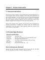
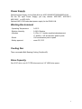
RACK-814 CHASSIS
USER’S MANUAL
Copyright Notice
This document and product is copyrighted, April 2000, by ICP Electronics Inc. All
rights are reserved. No part of this manual may be reproduced, copied, or
translated without prior notice to ICP Electronics Inc.
The information provided in this document is for reference only. We do not assume
any responsibility arising out of the application of the products. This manual is
subject to change without any notice.
Rack-814, ICP are trademark of ICP Electronics Inc.
1
Table of Contents
Chapter 1
Product Information
1.1 General Information
1.2 Product Specifications
1.3 Dimensions
Chapter 2
System Setup
2.1 The Front Panel of Rack-814
2.2 Removing the chassis cover
2.3 Disk Drives Installation
2.4 Replacing the Filter
2.5 The Card Clamp & Backplane Installation
2.6 Power Supply Installation
2.7 Fan Installation
Appendix A
Passive Backplane
Appendix B
Exploded Diagram
2
Chapter 1 Product Information
1.1 General Information
Rack-814 is a PC/AT compatible computer designed for Industrial applications. It is
a steel rugged chassis specially designed to work under harsh environment for
high reliability application. The Rack-814 features 14 slots Passive Backplanes and
high reliability AC/DC Input Power Supply (Options available are: ACE-920A,
ACE-932A, ACE932T, ACE925T, ACE925C, ACE-916V ACE-935A and ACE-C232).
Specially equipped with Keyboard Port on front side for easy access.
Rack-814 will withstand shock, vibration, dust and wide range of temperature in
Industrial environments. A lockable door protects drives and switches from
unauthorized misuse and particle. Three removable cooling-fans installed in the
rear for optimum cooling system.
1.2 Product Specifications
General specification
- Construction
- Disk Driver
- Cooling Fan
- Indicator
-UBS PORT
- Dimension
:
:
:
:
:
:
Heavy-duty steel
One 5.25” drive and Two 3.5” drive(FDD&HDD) space
Three Ball bearing fans(8cmX3)
Two LEDs to monitor the status of HDD and Power
In the front panel
431(W)X176(H)X454.7(D)
mm
Passive Backplanes (Optional)
Features 14 slots Full-length backplanes with the options: BP-14S, BP-14SD,
PCI-14S, PCI-14S2, PCI-13SD, PX-14S, PX-14S2 and IP-14S
3
Power Supply
Optional power Supply for the Rack-814 are: ACE-920A/932T/935AI/925C/916V
For the DC input Power Supply, you may choose: ACE-932T, ACE-925T,
ACE-925C or ACE-916V.
Optional ACE-C232 redundant power supply for the RACK-814.
Working Environment
- Operating Temperature
- Relative Humidity
- Vibration
:
:
:
- Shock
- Safety approval
:
:
0~50°C
5~95% Relative
5-17Hz, 0.1” double amplitude displacement
17-640Hz, 1.5G acceleration peak to peak
10G acceleration peak to peak
meet CE, FCC
Cooling Fan
Three removable Ball Bearing Cooling Fan(8cmX3)
Drive Capacity
One 5.25” drive ,one 3.5” FDD drive and one 3.5” HDD drive space
4
481.8
465.0
431.0
102.0
176.0
92.1
92.1
454.7
465.4
500.4
92.1
33.4
1.3 Dimensions
88.0
O 10
5
Chapter 2 Installation Procedure
The following set up procedures are provided to assist you in installing the system
unit, please follow the steps below:
2.1 The Front Panel of Rack-814
3.5" F DD
5.25" C D-RO M
HDD-LE D
P OWER -LED
RE S E T-B UTTOM
E XT. KE YB OARD
US B P OR T
6
2.2 Removing the chassis cover
The cover is mounted by 6 screws at each side and the top of the chassis,
remove them and slide the cover to the rear of the chassis. Figure below
shows how to remove the chassis cover.
7
2.3 Disk Drives installation
1. Open the disk drive door in the front panel
2 . Remove the disk drive bay
3. Attach the FDD to the bracket with four screws and connect FDD cable
& power cable to the FDD.
4. Attach the HDD to the bracket with four screws and connect a 40-pin
flat cable & power cable to the HDD.
8
2.4 Replacing the Filter
The filter of the Rack-814 is located at the front end of the chassis. The filter
should be removed and cleaned at least once a month to achieve optimum
performance. The filter can be removed simply by turn the key-lock to the
counter clock-wise direction. Take out the old filter, replace it with the new one
if it’s already worn out. Then close and lock the filter door.
FILTER
9
2.5 The Backplane & Card Clamp Installation
To install the backplanes in the chassis, remove the clamp panel first, then put
the backplanes inside the chassis and screw it.
Figure below illustrates how to install the backplanes on the Rack-814.
10
2.6 Power Supply Installation
2.6.1Power Supply for the Rack-814 installation: ACE-920A/932A/935AI/925T…..
SCREW×2
SCREW×4
11
2.6.2Redundant Power Supply for the Rack-814 installation:ACE-C232C
SCREW×2
SCREW×2
12
2.7 Fan Installation
NC
NC
GND
+12V
SCREW×4
Removable cooling-fan:
By two spring screw
13
311.43
246.33
140.64
211.91
PASSIVE BACKPLANES
95.10
18.03
0.00
APPENDIX A
0.00
MODEL:PX-14S VER:E
3-1
3-2
3-3
3-4
P8
P9
165.33
175.39
255.58
299.64
249.71
178.14
0.00
140.64
264.39
PX-14S
1
P8
P8
7
Brown
Blue
White
P9
Black
ACE-932A
POWER
SUPPLY
P9
GND
WHITE
BLACK
BLUE
Brown
Blue
Black
White
BROWN
14
APPENDIX B
EXPLODED DIAGRAM
18
16
15
17
20
21
25
19
14
13
26
24
23
22
12
11
3
10
9
7 8
2
5
6
1
4
P A R T L IS T
ITE M
P AR T N O .
1
2
3
4
5
6
7
8
9
10
11
12
13
14
15
16
17
18
19
20
21
22
23
24
25
26
4 1 0 0 1 -0 0 2 9 XX
4 1 0 1 2 -0 0 2 5 XX
4 5 0 0 7 -0 0 0 1 0 4
3 2 0 0 0 -0 0 0 0 9 1
1 3 1 L P 0 1 -0 0 -0 1 0
4 5 0 0 2 -0 0 0 1 0 3
0 1 1 B P 1 4 S -0 0 -0 0 0
4 1 0 1 3 -0 0 1 5 0 2
4 1 0 0 6 -0 0 7 5 XX
4 1 0 1 5 -0 0 3 2 XX
3 2 1 0 0 -0 0 0 2 2 9
3 1 1 0 0 -0 0 0 0 2 4
4 1 0 0 8 -0 0 4 7 XX
4 1 0 0 9 -0 0 0 2 XX
4 6 0 0 2 -0 0 0 2 0 0
4 1 0 0 5 -0 0 3 2 XX
6 3 A C E 9 3 2 A -0 0 0
4 1 0 1 1 -0 0 8 7 XX
4 1 0 1 1 -0 0 8 8 XX
4 1 0 1 0 -0 0 1 0 0 2
4 6 0 1 5 -0 0 1 8 0 0
4 1 0 1 6 -0 0 1 5 XX
4 1 0 1 6 -0 0 1 4 XX
3 1 3 0 0 -0 0 0 0 0 5
4 1 0 2 0 -0 0 1 9 XX
4 5 0 0 3 -0 0 0 3 0 3
D E S C R IP TIO N
A S S E M B LY F R O N T P A N E L
DO O R P ANE L
LO C K
US B C AB L E
LP -0 1 P A N E L IP 5 2 A
B R AC K E T
B P -1 4 S (B c a k -p la n e )
P C B -B A S E
A S S E M B LE B A S E
IN TE R F A C E C A R D B R A C K E T
W IR E C A B LE F A N
F A N (8 0 m m /2 W ire )
U P P E R C O VE R
F A N G R IL LE
LE A D -P C B (C G -9 A )
LE A D -S LID E -S E T
P o w e r/A C E -9 3 2 A
HD D S E T
D R IV E R S E T
F IL TE R -F IX
F ILTE R
H IN G E -R
H IN G E -L
P O W E R S W ITC H (O N /O F F )
H A N D L E -S E T
HA NDL E
Q 'T Y
1
1
1
1
1
14
1
1
1
1
1
3
1
3
14
1
1
1
1
1
1
1
1
1
2
2
R E M AR K
O P T IO N
O P T IO N
15