1
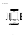
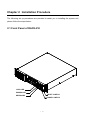
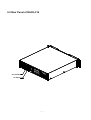
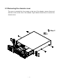
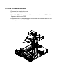
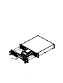
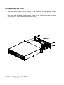
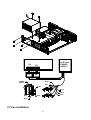
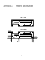
RACK-210 CHASSIS
USER’S MANUAL
Copyright Notice
This document and product is copyrighted, October 1998, by ICP Electronics Inc. All
rights are reserved. No part of this manual may be reproduced, copied, or translated
without prior notice to ICP Electronics Inc.
The information provided in this document is for reference only. We do not assume any
responsibility arising out of the application of the products. This manual is subject to
change without any notice.
RACK-210, ICP are trademark of ICP Electronics Inc.
--
1
Table of Contents
Chapter 1
Product Information
1.1 General Information
1.2 Product Specifications
1.3 Dimensions
Chapter 2
System Setup
2.1 Front Panel of RACK-210
2.2 Rear Panel of RACK-210
2.3 Removing the chassis cover
2.4 Backplane Installation
2.5 Disk Drives Installation
2.6 Replacing the Filter
2.7 Power Supply Installation
2.8 Fan Installation
Appendix A
Passive Backplane
Appendix B
Exploded Diagram
--
2
.
Chapter 1 Product Information
1.1 General Information
RACK-210 Wall-mount IPC chassis is a rugged PC/AT compatible computer designed for
the factory floor and other Industrial harsh environment. The RACK-210 features 5 slots
Passive Backplanes and high reliability AC Input Power Supply : ACE-920A.
1.2 Product Specifications
General specification
- Construction
- Disk Driver
- Cooling Fan
- Indicator
- Dimension
:
:
:
:
:
Heavy-duty steel
Supports one 3.5” FDD and one CD -ROM , two 3.5” HDD
One ball bearing fan for add-on cards cooling
Two LEDs to monitor the status of HDD and Power Supply
431 x 477.2 x 88 mm ( W x D x H )
Passive Backplanes (Optional)
BP-5S
5-slot ISA-bus Backplane
PCI-5SD 5-slot ISA/PCI bus Backplane
PCI-6SR 6-slot ISA/PCI bus Backplane
Power Supply
Standard equipped power supply for the RACK-210 is : ACE-920A
--
3
Working Environment
- Operating Temperature
- Relative Humidity
- Vibration
:
:
:
- Shock
- Safety approval
:
:
0~50°C
5~95% Relative
5-17Hz, 0.1” double amplitude displacement
17-640Hz, 1.5G acceleration peak to peak
10G acceleration peak to peak
meet CE, FCC
Cooling Fan
One ball bearing fan for add-on cards cooling
Drive Capacity
Supports one 3.5” FDD and one CD -ROM, two 3.5” HDD
--
4
1.3 Dimensions
457.20mm
477.20mm
431.00mm
483.00mm
466.00mm
76.30
88.00
6.5x10 HOLE
--
5
Chapter 2 Installation Procedure
The following set up procedures are provided to assist you in installing the system unit,
please follow the steps below:
2.1 Front Panel of RACK-210
H.D.D-LED
POWER-LED
RESET SWITCH
KEYBOARD
POWER SWITCH
--
6
2.2 Rear Panel of RACK-210
AC-OUTPUT
AC-INPUT
--
7
2.3 Removing the chassis cover
The cover is mounted by four screws on the top of the chassis, remove them and
slide the cover to the rear of the chassis. Figure below shows how to remove the
chassis cover.
Step 2
Step 1
--
8
2.4 Backplane Installation
Figure below illustrates how to install the backplanes on the RACK-210
Step 2
Step 1
--
9
-- 10
2.5 Disk Drives Installation
1. Remove the chassis top cover
2. Remove the disk drive bay
3. Attach the FDD to the bracket with four screws and connect FDD cable
& power cable to the FDD.
4. Attach the HDD to the bracket with four screws and connect a 40-pin flat
cable & power cable to the HDD.
-- 11
Step 2
Step 1
-- 12
2.6 Replacing the Filter
The filter of the RACK-210 is located at the front end of the chassis. Under
continuous use, the filter should be removed about once a mounth. To replace the
filter, open and close the door by screws . Take out the old filter and slide the new
one into place . Then close and lock the filter door.
Step1
Step2
2.7 Power Supply Installation
-- 13
P9
7
P9
ACE-920A
POWER
SUPPLY
P8
1
P8
POWER
SWITCH
Brown
Blue
Brown
Black
White
Blue
Black
White
2.7 Fan Installation
-- 14
GND
ACE-920A
POWER
SUPPLY
+12V (RED)
GND (BLACK)
-- 15
APPENDIX A
PASSIVE BACKPLANES
LEFT SIDE
RIGHT SIDE
80.00 mm
73.05 mm
23.55 mm
11.70 mm
0.00mm
-- 16
261.00 mm
253.30 mm
93.30 mm
0.00 mm
0.00 mm
APPENDIX B
EXPLODED DIAGRAM
-- 17