1
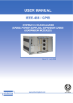
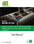
RACK-3000 CHASSIS
USER’S MANUAL
Copyright Notice
This document and product is copyrighted, May 2001, by ICP Electronics Inc. All
rights are reserved. No part of this manual may be reproduced, copied, or
translated without prior notice to ICP Electronics Inc.
The information provided in this document is for reference only. We do not assume
any responsibility arising out of the application of the products. This manual is
subject to change without any notice.
Rack-3000 is trademark of ICP Electronics Inc.
1
Table of Contents
Chapter 1
Product Information
1.1 General Information
1.2 Product Specifications
1.3 Dimensions
Chapter 2
System Setup
2.1 Filter of the Lockable Door
2.2 The Front Panel of Rack-3000
2.3 Removing the chassis cover
2.4 Disk Drives Installation
2.5 Fan Installation
2.6 Power Supply Installation
2.7 The Card Clamp & Backplane Installation
Appendix A
Passive Backplane
Appendix B
Power supply
Appendix C
Drive Bay
2
Chapter 1 Product Information
1.1 General Information
Rack-3000 is a PC/AT compatible computer designed for industrial applications. It
is a steel rugged chassis specially designed to work under harsh environment for
high reliability application. The Rack-3000 features 14-slots passive backplanes
and high reliability AC/DC input power supply (options available are: ACE-920A,
ACE-932A, ACE932T, ACE925T, ACE925C, ACE-916V, ACE-935A, ACE-83A and
ACE-R30A)…
Rack-3000 will withstand shock, vibration, dust and wide range of temperature in
industrial environments. A lockable door protects drives and switches from
unauthorized misuse and particle. Two removable cooling-fans installed in the front
panel for optimum cooling system.
1.2 Product Specifications
General specification
- Construction
- Disk Driver
:
:
- Cooling Fan
- Indicators
- Dimension
:
:
:
Heavy-duty steel
Three 5.25” drive and two 3.5” drive (FDD or HDD) open
space one 3.5” internal HDD space
Two ball bearing fans (8cm)
Three LEDs display for power HDD and alarm activities
19” rackmount, 4U height, 431(W) X 176(H) X 520(D) mm
Passive Backplanes (Optional)
Features 14 slots full-length backplanes with the options: PCI-14S, PCI-14S2,
PCI-14S3, BP-14S, PX-14S, PX-14S2, PX-14S3, PX-14S5IP-14S and IP-14S3…
3
Power Supply
PS/2 size of AT/ATX power supply for Rack-3000 are ACE-920A/ 932T/ 935A/
925C/ 916V/ 832A. For DC input power supply, you may choose: ACE-932T,
ACE-925T, ACE-925C or ACE-916V. ACE-R30A redundant power supply is
optional.
Working Environment
- Operating Temperature
- Relative Humidity
- Vibration
:
:
:
- Shock
- Safety approval
:
:
0~50°C environment
5~95% Relative
5-17Hz, 0.1” double amplitude displacement
17-640Hz, 1.5G acceleration peak to peak
10G-acceleration peak to peak
meet CE, FCC
Cooling Fan
Two removable ball bearing cooling fan (8cmX8cm)
Drive Capacity
Three 5.25” drive and two 3.5” open FDD or HDD space and one 3.5” internal HDD
drive space
4
1.3 Dimensions
D
E
L
M
R
A
L
A
N
A
F
D
E
L
D
D E
D L
H
R
E
W
O
P
5
Chapter 2 Installation Procedure
The following procedures are provided to assist you in installing the Rack-3000,
please follow the steps below:
2.1 Filter of the Lockable Door
A lockable door installed in the front panel .The filter is located at the inner of
the door. It should be cleaned at least once a month to achieve optimum
performance. The filter can be removed simply by slide out the locker. If filter
worn out, replace new one, lock the filter locker.
6
2.2 The Front Panel of Rack-3000
The drives, fans and power switch in the front panel. They protect by lockable
door for unauthorized misuse and particle environment.
7
2.3 Removing the chassis cover
The top cover is fixed by 6 screws at each side and the top of the chassis, remove them and
slide the cover to the rear of the chassis. Figure below shows how to remove the chassis
cover.
8
2.4 Disk Drives installation
1. Open the lockable door in the front panel
2. Remove 4 screws that lock the disk drive bay
3. Pull out the disk drive bay
4. Attach the drivers to the bracket with screws and connect flat cable &
power cable to the driver
5. Plug in the drive bay and lock it by screws.
SCREW X 2
SCREW X 2
9
2.5 Fan Installation
The Rack-3000 is easy to install the fan module in the chassis. Plug in the
plastic locker, connect the fan cable with the A60 controller board.
Figure below illustrates how to install the fan module.
Removable cooling-fan:
By two spring screw
YELLOW : Signal Feedback
RED : +12
BLACK : GND
SCREW X 4
10
2.6 Power Supply Installation
2.6.1 General Power Supply
For the Rack-3000 installation: ACE-920A/ 932A/ 932T/ 935A /925T/ 925C/ 916V/
832A…
SCREW X 2
SCREW X 4
11
2.6.2 Redundant Power Supply for the Rack-3000 installation: ACE-R30A
SCREW X 2
SCREW X 2
12
2.7 The Card Clamp & Backplane Installation
Figure below illustrates how to install the backplanes on the Rack-3000.
To install the backplanes in the chassis, remove the clamp panel first, then put
the backplanes inside the chassis and screw it.
13
Cable Management
- AT power supply
PX-14S
1
P8
P8
7
P9
ACE-932A
POWER
SUPPLY
P9
GND
Blue
White
Brown
Brown
Blue
Black
Black
White
- ATX power supply
PX-14S
BLACK
C
P
U
C
A
R
D
ACE-832A
POWER
SUPPLY
RED
14
A60 & IP-52B Controller
5
TO IP-52B
TO CPU card/ ATX MB
HDD and Power LED connector
4
JP1
FAN1
JP3
FAN2
JP4
JP6
3
JP2
JP5
FAN3
JP8
FAN4
2
1
TO POWER SUPPLY
ITEM
PART NO
1 32100-031101
2 32100-000260
3 131A60-00-010
4 32100-044500
5 131LP01-02-011
SPECIFICATION Q'TY
REMARK
Power cable
1
Fan Extend Cable
1
A60 Control Panel 1
1 for reset HDD Power Alarm
Cable
1 Control Panel
IP-52B
15
ALARM LED
POWER LED
POWER IN
A60
TO FAN
Front
Rear
IP-52B
16
A60 Alarm board (Ver. 1.1)
(Pin Define)
Name
JP1
JP3
JP5
JP8
JP2
JP6
JP4
JP7
JP9
Pin
1
2
3
1
2
3
1
2
3
1
2
3
1
2
3
1
2
1
2
1-2
ˇ
×
ˇ
×
Descripon
GND
Fan1 VCC
Fan1 sensor
GND
Fan2 VCC
Fan2 sensor
GND
Fan3 VCC
Fan3 sensor
GND
Fan4 VCC
Fan4 sensor
12V
5V
GND
Power good LED display
GND
Fan fail LED+
Fan fail LED3-4
Monitor speed limit
ˇ
30 rpm
ˇ
500 rpm
×
1000 rpm
×
1500 rpm
1-2
3-4
5-6
FAN2 disable
FAN3 disable
FAN4 disable
PS: ×=Open(開路)
ˇ=Short(短路)
Please firstly use Fan 1, otherwise it's void to disable Fan X.
17
APPENDIX A
Model
PCI-14S
PCI-14S2
PCI-14S3
BP-14S
PX-14S
PX-14S1
PX-14S2
PX-14S3
PX-14S5
IP-14S
IP-14S3
ISA
8
7
8
14
6
5
5
1
5
8
9
PASSIVE BACKPLANES
PCI
4
4
4
0
7
7
7
12
7
4
2
PICMG
2
2
2
0
2
2
2
2
2
0
0
PCISA
0
0
0
0
0
0
0
0
0
2
3
Remark
ISA/PICMG option
PCI/PICMG option
PCI-14S Serial
18
BP-14S Serial
PX-14S Serial
19
APPENDIX B
POWER SUPPLY
RACK-3000 was designed for PS/2 size power supply.
PS/2 POWER SUPPLY SERIAL
ACE-R30A
20
Model Name
ACE-920A
Description
Input Range
AC
DC
Output
Voltages
ACE-832A
350W PS/2 size AC 300W PS/2 size ATX
input power supply power supply
85~140VAC or
180~270VAC
@47~63Hz
-
95~132VAC,
180~264VAC
@47~63Hz
Auto-range
-
300W
300W
350W
300W
+5V
20A
40A
33A
40A
30A
+3.3V
-
-
-
-
28A
+12V
4A
12A
8A
8A
15A
-5V
0.5A
0.5
0.5A
0.3A
0.3A
-12V
0.5A
3A
3A
0.7A
0.8A
+5VSB
-
-
-
-
2A
216700
141000
124100
200050
100000
UL/CSA/TUV
UL/CSA/TUV/CE
UL/CSA/TUV
UL/CSA/TUV
UL/CSA/TUV
ACE-916V
ACE-925T
ACE-925C
Description
MTBF
(hours)
Safety
250W PS/2 size AC 300W -48V PS/2
300W PS/2 size AC
input power supply size DC input power input power supply
(PFC)
supply
85~265VAC
85~130VAC or
@47~63Hz
180~265VAC
@47~63Hz
Auto-switch
-40~-70VDC
-
ACE-935A
200W
Model Name
Output
Voltages
ACE-932A
Rating (max.)
MTBF
(hours)
Safety
Input Range
ACE-932T
AC
160W PS/2 size 12V 250W PS/2 size
DC input power
-48V DC input
supply
power supply
-
ACE-R30A
250W PS/2 size 24V 300W PS/2 size ATX redundant power
DC input power
supply (include two ACE-R30A power
supply
module)
90~132V or 180~264VAC
@47~63Hz Switch select
DC
8.5~16VDC
-40~-65VDC
19~30VDC
-
Rating (max.)
160W
250W
250W
300W
+5V
25A
30A
30A
+3.3V
-
-
-
+12V
7A
12A
12A
-5V
0.5A
1A
1A
35A
(2.5A min.)
15A
(0.5A min.)
15A
(0.5A min.)
0.5A
-12V
0.5A
2A
2A
0.8A
+5VSB
-
-
-
1.5A
202500
198500
206000
50000
UL/CSA/TUV/CE
UL/CSA/TUV/CE
UL/CSA/TUV/CE
UL/CSA/TUV
21
APPENDIX C
Drive Bay
5.25" Drive Bay
3 open space
3.5" Drive Bay
2 open
1 Internal space
22