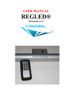
Download STIMULOPT User Manual
Transcript
STIMULOPT USER MANUAL
Version
005
Optokinetic ball
This document explains the features and utilization of the device
Stimulopt developed by FRAMIRAL.
Stimulopt User Manual
Version 005
Summary
I)
Presentation.................................................................................................................................................... 3
II)
Installation precautions ................................................................................................................................ 4
III)
Utilization ................................................................................................................................................... 9
IV)
Maintenance ............................................................................................................................................ 13
V)
Troubleshooting ........................................................................................................................................... 14
2
Stimulopt User Manual
I)
Version 005
Presentation
The STIMULOPT® is a device for
optokinetic stimulation, using a reflective ball,
illuminated by a powerful white light source,
rotating on two axes.
The projection on the side walls, ceiling and
floor, of a white room is usually
uncomfortable.
Figure 1 - Stimulopt
The rotation is done by step-to-step motors, accurate and quiet, controlled by an electronic system.
The device is preferably set up on a wall shelf, 2m high from the floor.
The light can be oriented, and offers a precise focusing on the wall, regarding the size of the room,
and an adjustable size of the light spots.
The device is powered with a transformer 240V/110V to 15V.
There are three ways to pilot this device :
-
Via Touchscreen
Via Infrared remote controller
Via computer (Multitest Software, through Multitest Platform)
CERTIFIED
3
Stimulopt User Manual
II)
Version 005
Installation precautions
Figure 2 - Stimulopt
In order to get nice light spots on your walls, it is advised to place the device on the edge of a wall
shelf. This shelf should be centered in the middle of the projection wall. The patient has to stand
under the device, in order to avoid shadows (see Figure 2 - Stimulopt).
Place the USB light as low as you can, and direct the light beam to the ball, in order to get an
evenly spread set of light dots on your wall.
The room walls should be as clear as possible (white is the best), and entirely dark. Watch out for
light under the doors and windows.
The device should be placed around 2m high, for a better projection. Don’t forget that the back axis
of the device can rotate, so the maximal height of the device is 45cm.
4
Stimulopt User Manual
Version 005
Setting up the USB light:
Figure 3 – Plug in the USB light
The USB connector of the light plugs in the USB port located in front of the device.
Electrical / Command plug in:
Link device – touch screen:
Link the device to the touch screen with the RJ11 cable.
Figure 4 - RJ11 Cable
5
Stimulopt User Manual
Version 005
Figure 5 – Touch screen connection
The connectors have to be locked in their connection socket (click).
Power:
Plug the transformer to the wall socket:
Figure 6 - Power
Plug the other side to the appropriate socket at the back of the device.
Figure 7 - Power plugin
A fuse 5x20mm - 2A has to be put in the fuse socket.
6
Stimulopt User Manual
Version 005
Start the device:
Swith on the device with the I/O switch located at the back. The red LED should light on, and the
touch screen should initialize:
Figure 8 – Touch screen
Power
Plateforme
Connection
Touch screen
Fuse
Figure 9 - Connections
On/Off
7
Stimulopt User Manual
Version 005
Setting up the light:
Once the device is correctly positioned in the room, you can adjust the USB light in order to get a
good quality of light dots on the walls, ceiling and floor.
First, turn on the ball by clicking on any of the “play” icon on the touch screen:
Figure 10 – Touch screen
The light should turn on automatically.
Modify the distance between the ball and the light, to change the size of the light spots (Figure 11).
The closest the light to the ball, the bigger the light spots on the wall.
You can also change the luminosity (Figure 11).
Luminosity
Figure 12 – USB Light
Figure 11 – Luminosity button
8
Stimulopt User Manual
III)
Version 005
Utilization
The device can be controlled with:
-
The touch screen.
The infrared remote controller
The MULTITEST plateform (please refer to the MULTITEST user manual for this solution)
Touch screen :
This touch screen allows you to control the device, and visualize the current parameters (speed,
cycles…).
Figure 13 – Touch screen
You can set a speed and a direction to each of the two motors.
You can also start an automated cycle, in which speeds and direction are pre-defined.
When cycle ‘0’ is selected, the control is manual: the ball will turn as specified by the practitioner,
for an unlimited time.
Frames « BALL » or « BACK » :
You can set/find the speed of the rotation, by step of 1°/s. ‘0’ means that the motor is off.
Two groups of button allow you to control the two motor « BALL » and « BACK »:
9
Stimulopt User Manual
Version 005
Turns On/Off the motor, back to its previous speed.
Change the direction of the rotation (only on cycle ‘0’).
Speed up or slow down the rotation by clicking on ‘+’ or ‘-‘. If the
motor is off, you can still pre-set the speed.
Frame « CYCLE » :
By clicking on this icon (‘CYCLE’ frame), you can select a running cycle:
10
Stimulopt User Manual
Version 005
CYCLE 1: alternative direction mode, invariable speed.
Icons
(ball rotation).
allows you to set the time lapse between every direction change
CYCLE 2: alternative direction mode – random time-lapse (1 to 59 s) invariable
speed.
CYCLE 3: alternative speed mode – random time-lapse, invariable direction.
CYCLE 4: alternative speed and direction mode – random time-lapse.
The parameters are saved when the device is turned off. They will be restored when the device is
turned on (power cuts).
Infrared Remote Controller :
Figure 14 – Remote controller
The remote controller offers the same functions as the touch screen.
.
11
Stimulopt User Manual
Version 005
For a better efficiency, it is advised to target the IR receiver located on the front of the device when
using the IR remote controller. The range is about 4 to 5 meters.
Functions available on the remote controller:
The column on the left side allows you to control the ‘BALL’ motor as the ‘BALL’ frame of the touch
screen:
Motor On/Off.
Reverse direction.
Speed up and slow down.
The column in the middleallows you to control the ‘BACK’ motor as the ‘BACK’ frame on the touch
screen:
Motor On/Off.
Reverse direction.
Speed up and slow down.
The column on the right side is for special functions:
Simultaneous direction change on both motor.
Memorization of the current parameters (speed, direction, cycles…).
Call back of the previously memorized parameters.
When in ‘CYCLE’ mode ,
allows you to set time period between each direction inversion (1s to 59s)
12
Stimulopt User Manual
IV)
Version 005
Maintenance
It is very important to clean up the mirrors on the ball regularly, as dust can reduce the quality of
the projected light dots.
Power should be turned off when cleaning the device.
Use an appropriate cleaning solution. No acetone.
Dry off with a cloth, without forcing too much on the ball. You can manually rotate it slowly on both
axes to get to the hidden parts.
Figure 15 - Cleaning
13
Stimulopt User Manual
V)
Version 005
Troubleshooting
Faded light:
Check the luminosity setting
Replace the USB light
The device does not turn on:
Check the plugs.
Replace the fuse.
Remote controller not responding:
Reset the controller
Unclip the top part of the controller (no screws).
Hold on the Reset button, and click on any other button. Release the Reset button.
Replace the batteries
The batteries lifetime will depend on the utilization. You can replace the batteries once a year to
keep the controller performances. Replace the 3 batteries (AAA 1,5V / LR03) ensuring the polarity
is respected.
Reset Button
Figure 16 – Batteries replacement
14
Stimulopt User Manual
Version 005
Table of Illustrations
Figure 1 - Stimulopt ............................................................................................................................................... 3
Figure 2 - Stimulopt ............................................................................................................................................... 4
Figure 3 – Plug in the USB light .......................................................................................................................... 5
Figure 4 - RJ11 Cable .......................................................................................................................................... 5
Figure 5 – Touch screen connection .................................................................................................................... 6
Figure 6 - Power .................................................................................................................................................... 6
Figure 7 - Power plugin ........................................................................................................................................ 6
Figure 8 – Touch screen ........................................................................................................................................ 7
Figure 9 - Connections........................................................................................................................................... 7
Figure 10 – Touch screen ...................................................................................................................................... 8
Figure 11 – Luminosity button .............................................................................................................................. 8
Figure 12 – USB Light ........................................................................................................................................... 8
Figure 13 – Touch screen ...................................................................................................................................... 9
Figure 14 – Remote controller ........................................................................................................................... 11
Figure 15 - Cleaning ........................................................................................................................................... 13
Figure 16 – Batteries replacement ................................................................................................................... 14
15
Stimulopt User Manual
Version 005
FRAMIRAL
107, avenue Jean Maubert
06130 GRASSE
FRANCE
Tél : +33 422 480 107
Fax : +33 956 372 472
Email : [email protected]
16


