1
FSO-11 user's manual.book Page 1 Friday, October 19, 2012 10:30 AM
ABB industrial drives
User’s manual
FSO-11 safety functions module
FSO-11 user's manual.book Page 2 Friday, October 19, 2012 10:30 AM
List of related manuals
Drive hardware manuals and guides
ACS880-01 hardware manual
ACS880-01 quick installation guide for frames R1 to R3
ACS880-01 quick installation guide for frames R4 and R5
ACS880-01 quick installation guide for frames R6 to R9
ACS880-04 hardware manual
ACS880-07 hardware manual
ACS880-104 inverter modules hardware manual
ACS880-107 inverter units hardware manual
BCU-02/12/22 control units hardware manual
ACS-AP-x assistant control panels user’s manual
Code (English)
3AUA0000078093
3AUA0000085966
3AUA0000099663
3AUA0000099689
3AUA0000128301
3AUA0000105718
3AUA0000105718
3AUA0000102519
3AUA0000113605
3AUA0000085685
Drive firmware manuals and guides
ACS880 primary control program firmware manual
Quick start-up guide for ACS880 drives with primary
control program
3AUA0000085967
3AUA0000098062
General safety manuals and guides
Functional safety; Technical guide No. 10
Safety and functional safety; A general guide
3AUA0000048753
1SFC001008B0201
Option manuals
FSO-11 safety function module user's manual
3AUA0000097054
Tool manuals
Drive composer start-up and maintenance PC tool user's
manual
3AUA0000094606
You can find manuals and other product documents in PDF format on the Internet. See section Document library on
the Internet on the inside of the back cover. For manuals not available in the Document library, contact your local ABB
representative.
FSO-11 user's manual.book Page 3 Friday, October 19, 2012 10:30 AM
User’s manual
FSO-11 safety functions module
Table of contents
1. Safety
7. Installation
10. Start-up
© 2012 ABB Oy. All Rights Reserved.
3AUA0000097054 Rev B
EN
EFFECTIVE: 2012-10-15
FSO-11 user's manual.book Page 4 Friday, October 19, 2012 10:30 AM
FSO-11 user's manual.book Page 5 Friday, October 19, 2012 10:30 AM
Table of contents 5
Table of contents
List of related manuals . . . . . . . . . . . . . . . . . . . . . . . . . . . . . . . . . . . . . . . . . . . . . . . . . . . . . . . 2
1. Safety
Contents of this chapter . . . . . . . . . . . . . . . . . . . . . . . . . . . . . . . . . . . . . . . . . . . . . . . . . . . . . . 11
Use of warnings . . . . . . . . . . . . . . . . . . . . . . . . . . . . . . . . . . . . . . . . . . . . . . . . . . . . . . . . . . . . 11
2. Introduction to the manual
Contents of this chapter . . . . . . . . . . . . . . . . . . . . . . . . . . . . . . . . . . . . . . . . . . . . . . . . . . . . . .
Exclusion of liability . . . . . . . . . . . . . . . . . . . . . . . . . . . . . . . . . . . . . . . . . . . . . . . . . . . . . . . . .
Applicability . . . . . . . . . . . . . . . . . . . . . . . . . . . . . . . . . . . . . . . . . . . . . . . . . . . . . Safety
..........
Compatible products . . . . . . . . . . . . . . . . . . . . . . . . . . . . . . . . . . . . . . . . . . . . . . . . . . . . . . . .
Drives . . . . . . . . . . . . . . . . . . . . . . . . . . . . . . . . . . . . . . . . . . . . . . . . . . . . . . . . . . . . . . . .
Tools . . . . . . . . . . . . . . . . . . . . . . . . . . . . . . . . . . . . . . . . . . . . . . . . . . . . . . . . . . . . . . . . .
Supported safety functions . . . . . . . . . . . . . . . . . . . . . . . . . . . . . . . . . . . . . . . . . . . . . . . . . . .
Target audience . . . . . . . . . . . . . . . . . . . . . . . . . . . . . . . . . . . . . . . . . . . . . . . . . . . . . . . . . . . .
Purpose of the manual . . . . . . . . . . . . . . . . . . . . . . . . . . . . . . . . . . . . . . . . . . . . . . . . . . . . . .
Contents . . . . . . . . . . . . . . . . . . . . . . . . . . . . . . . . . . . . . . . . . . . . . . . . . . . . . . . . . . . . . . . . .
Recommended reading . . . . . . . . . . . . . . . . . . . . . . . . . . . . . . . . . . . . . . . . . . . . . . . . . . . . . .
Related standards and directives . . . . . . . . . . . . . . . . . . . . . . . . . . . . . . . . . . . . . . . . . . . . . .
Definitions . . . . . . . . . . . . . . . . . . . . . . . . . . . . . . . . . . . . . . . . . . . . . . . . . . . . . . . . . . . . . . . .
Terms . . . . . . . . . . . . . . . . . . . . . . . . . . . . . . . . . . . . . . . . . . . . . . . . . . . . . . . . . . . . . . . . . . .
Abbreviations . . . . . . . . . . . . . . . . . . . . . . . . . . . . . . . . . . . . . . . . . . . . . . . . . . . . . . . . . . . . . .
Safety related . . . . . . . . . . . . . . . . . . . . . . . . . . . . . . . . . . . . . . . . . . . . . . . . . . . . . . . . . .
Other . . . . . . . . . . . . . . . . . . . . . . . . . . . . . . . . . . . . . . . . . . . . . . . . . . . . . . . . . . . . . . . . .
Certificate . . . . . . . . . . . . . . . . . . . . . . . . . . . . . . . . . . . . . . . . . . . . . . . . . . . . . . . . . . . . . . . .
13
13
13
14
14
14
14
14
14
15
16
16
17
18
19
19
19
20
3. Safety information and considerations
Contents of this chapter . . . . . . . . . . . . . . . . . . . . . . . . . . . . . . . . . . . . . . . . . . . . . . . . . . . . . .
Meeting the requirements of the Machinery Directive . . . . . . . . . . . . . . . . . . . . . . . . . . . . . . .
Responsibilities . . . . . . . . . . . . . . . . . . . . . . . . . . . . . . . . . . . . . . . . . . . . . . . . . . . . . . . . . . . .
Safety considerations . . . . . . . . . . . . . . . . . . . . . . . . . . . . . . . . . . . . . . . . . . . . . . . . . . . . . . .
Response times . . . . . . . . . . . . . . . . . . . . . . . . . . . . . . . . . . . . . . . . . . . . . . . . . . . . . . . .
FSO-11 diagnostics . . . . . . . . . . . . . . . . . . . . . . . . . . . . . . . . . . . . . . . . . . . . . . . . . . . . . .
I/O . . . . . . . . . . . . . . . . . . . . . . . . . . . . . . . . . . . . . . . . . . . . . . . . . . . . . . . . . . . . . . . . . . .
Safety function acknowledgement modes . . . . . . . . . . . . . . . . . . . . . . . . . . . . . . . . . . . . .
Encoderless mode . . . . . . . . . . . . . . . . . . . . . . . . . . . . . . . . . . . . . . . . . . . . . . . . . . . . . .
Speed estimation . . . . . . . . . . . . . . . . . . . . . . . . . . . . . . . . . . . . . . . . . . . . . . . . . . . . . . .
Characteristics . . . . . . . . . . . . . . . . . . . . . . . . . . . . . . . . . . . . . . . . . . . . . . . . . . . . . . . . .
Proof testing . . . . . . . . . . . . . . . . . . . . . . . . . . . . . . . . . . . . . . . . . . . . . . . . . . . . . . . . . . .
Safety separation . . . . . . . . . . . . . . . . . . . . . . . . . . . . . . . . . . . . . . . . . . . . . . . . . . . . . . .
21
21
21
22
22
22
23
23
24
24
25
25
25
4. Overview
Contents of this chapter . . . . . . . . . . . . . . . . . . . . . . . . . . . . . . . . . . . . . . . . . . . . . . . . . . . . . . 27
FSO-11 user's manual.book Page 6 Friday, October 19, 2012 10:30 AM
6 Table of contents
System description . . . . . . . . . . . . . . . . . . . . . . . . . . . . . . . . . . . . . . . . . . . . . . . . . . . . . . . . .
FSO-11 and safety system components . . . . . . . . . . . . . . . . . . . . . . . . . . . . . . . . . . . . .
Layout . . . . . . . . . . . . . . . . . . . . . . . . . . . . . . . . . . . . . . . . . . . . . . . . . . . . . . . . . . . . . . .
Connections . . . . . . . . . . . . . . . . . . . . . . . . . . . . . . . . . . . . . . . . . . . . . . . . . . . . . . . . . . .
Type designation label . . . . . . . . . . . . . . . . . . . . . . . . . . . . . . . . . . . . . . . . . . . . . . . . . . .
Operational characteristics . . . . . . . . . . . . . . . . . . . . . . . . . . . . . . . . . . . . . . . . . . . . . . . .
28
28
29
30
30
31
5. Implemented safety functions
Contents of this chapter . . . . . . . . . . . . . . . . . . . . . . . . . . . . . . . . . . . . . . . . . . . . . . . . . . . . .
Safety functions . . . . . . . . . . . . . . . . . . . . . . . . . . . . . . . . . . . . . . . . . . . . . . . . . . . . . . . . . . .
General . . . . . . . . . . . . . . . . . . . . . . . . . . . . . . . . . . . . . . . . . . . . . . . . . . . . . . . . . . . . . . . . . .
Acknowledgement . . . . . . . . . . . . . . . . . . . . . . . . . . . . . . . . . . . . . . . . . . . . . . . . . . . . . .
Ramp monitoring . . . . . . . . . . . . . . . . . . . . . . . . . . . . . . . . . . . . . . . . . . . . . . . . . . . . . . .
Function indication . . . . . . . . . . . . . . . . . . . . . . . . . . . . . . . . . . . . . . . . . . . . . . . . . . . . . .
States . . . . . . . . . . . . . . . . . . . . . . . . . . . . . . . . . . . . . . . . . . . . . . . . . . . . . . . . . . . . . . . .
Cascade . . . . . . . . . . . . . . . . . . . . . . . . . . . . . . . . . . . . . . . . . . . . . . . . . . . . . . . . . . . . . .
Safe torque off (STO) . . . . . . . . . . . . . . . . . . . . . . . . . . . . . . . . . . . . . . . . . . . . . . . . . . . . . . .
STO base function . . . . . . . . . . . . . . . . . . . . . . . . . . . . . . . . . . . . . . . . . . . . . . . . . . . . . .
Safe brake control (SBC) . . . . . . . . . . . . . . . . . . . . . . . . . . . . . . . . . . . . . . . . . . . . . . . . . . . .
SBC after STO . . . . . . . . . . . . . . . . . . . . . . . . . . . . . . . . . . . . . . . . . . . . . . . . . . . . . . . . .
SBC before STO . . . . . . . . . . . . . . . . . . . . . . . . . . . . . . . . . . . . . . . . . . . . . . . . . . . . . . .
Safe stop 1 (SS1) . . . . . . . . . . . . . . . . . . . . . . . . . . . . . . . . . . . . . . . . . . . . . . . . . . . . . . . . . .
SS1 with time monitoring
..............................................
SS1 with ramp monitoring
..............................................
SS1 with speed limit activated SBC
.......................................
Safe stop emergency (SSE) . . . . . . . . . . . . . . . . . . . . . . . . . . . . . . . . . . . . . . . . . . . . . . . . . .
SSE with time monitoring
..............................................
SSE with ramp monitoring
.............................................
SSE with speed limit activated SBC . . . . . . . . . . . . . . . . . . . . . . . . . . . . . . . . . . . . . . .
Safely-limited speed (SLS) . . . . . . . . . . . . . . . . . . . . . . . . . . . . . . . . . . . . . . . . . . . . . . . . . . .
SLS with speed below monitored speed . . . . . . . . . . . . . . . . . . . . . . . . . . . . . . . . . . . . .
SLS with speed above monitored speed . . . . . . . . . . . . . . . . . . . . . . . . . . . . . . . . . . . . .
Safe maximum speed (SMS) . . . . . . . . . . . . . . . . . . . . . . . . . . . . . . . . . . . . . . . . . . . . . . . . .
33
33
34
34
35
36
37
38
40
40
42
42
44
46
46
48
49
50
52
53
54
55
55
56
57
6. Planning for installation
Contents of this chapter . . . . . . . . . . . . . . . . . . . . . . . . . . . . . . . . . . . . . . . . . . . . . . . . . . . . .
Requirements for designers and installers . . . . . . . . . . . . . . . . . . . . . . . . . . . . . . . . . . . . . . .
Mechanical installation . . . . . . . . . . . . . . . . . . . . . . . . . . . . . . . . . . . . . . . . . . . . . . . . . . . . . .
Installation site . . . . . . . . . . . . . . . . . . . . . . . . . . . . . . . . . . . . . . . . . . . . . . . . . . . . . . . . .
Electrical installation . . . . . . . . . . . . . . . . . . . . . . . . . . . . . . . . . . . . . . . . . . . . . . . . . . . . . . . .
General requirements . . . . . . . . . . . . . . . . . . . . . . . . . . . . . . . . . . . . . . . . . . . . . . . . . . .
Connections . . . . . . . . . . . . . . . . . . . . . . . . . . . . . . . . . . . . . . . . . . . . . . . . . . . . . . . . . . .
Power supply connection/cables . . . . . . . . . . . . . . . . . . . . . . . . . . . . . . . . . . . . . . . . . . .
Ensuring the EMC compatibility . . . . . . . . . . . . . . . . . . . . . . . . . . . . . . . . . . . . . . . . . . . .
Selecting control cables . . . . . . . . . . . . . . . . . . . . . . . . . . . . . . . . . . . . . . . . . . . . . . . . . .
Routing the cables . . . . . . . . . . . . . . . . . . . . . . . . . . . . . . . . . . . . . . . . . . . . . . . . . . . . . .
Standard function and wiring examples . . . . . . . . . . . . . . . . . . . . . . . . . . . . . . . . . . . . . .
59
59
59
59
60
60
60
61
61
61
61
62
FSO-11 user's manual.book Page 7 Friday, October 19, 2012 10:30 AM
Table of contents 7
7. Installation
Contents of this chapter . . . . . . . . . . . . . . . . . . . . . . . . . . . . . . . . . . . . . . . . . . . . . . . . . . . . . .
Mechanical installation . . . . . . . . . . . . . . . . . . . . . . . . . . . . . . . . . . . . . . . . . . . . . . . . . . . . . .
Electrical installation . . . . . . . . . . . . . . . . . . . . . . . . . . . . . . . . . . . . . . . . . . . . . . . . . . . . . . . .
Terminals . . . . . . . . . . . . . . . . . . . . . . . . . . . . . . . . . . . . . . . . . . . . . . . . . . . . . . . . . . . . .
Connection procedure . . . . . . . . . . . . . . . . . . . . . . . . . . . . . . . . . . . . . . . . . . . . . . . . . . . .
65
66
67
67
68
8. Installation checklists
Contents of this chapter . . . . . . . . . . . . . . . . . . . . . . . . . . . . . . . . . . . . . . . . . . . . . . . . . . . . . .
Checklists . . . . . . . . . . . . . . . . . . . . . . . . . . . . . . . . . . . . . . . . . . . . . . . . . . . . . . . . . . . . . . . .
General checklist . . . . . . . . . . . . . . . . . . . . . . . . . . . . . . . . . . . . . . . . . . . . . . . . . . . . . . . .
Common cause failure (CCF) checklists . . . . . . . . . . . . . . . . . . . . . . . . . . . . . . . . . . . . . .
71
71
72
72
9. Configuration
Contents of this chapter . . . . . . . . . . . . . . . . . . . . . . . . . . . . . . . . . . . . . . . . . . . . . . . . . . . . . . 73
Password . . . . . . . . . . . . . . . . . . . . . . . . . . . . . . . . . . . . . . . . . . . . . . . . . . . . . . . . . . . . . . . . . 73
Configuring the FSO-11 . . . . . . . . . . . . . . . . . . . . . . . . . . . . . . . . . . . . . . . . . . . . . . . . . . . . . . 73
FSO-11 parameters . . . . . . . . . . . . . . . . . . . . . . . . . . . . . . . . . . . . . . . . . . . . . . . . . . . . . . . . . 76
Configuring general settings . . . . . . . . . . . . . . . . . . . . . . . . . . . . . . . . . . . . . . . . . . . . . . . . . . 96
How to configure general settings . . . . . . . . . . . . . . . . . . . . . . . . . . . . . . . . . . . . . . . . . . . 96
Configuring I/O . . . . . . . . . . . . . . . . . . . . . . . . . . . . . . . . . . . . . . . . . . . . . . . . . . . . . . . . . . . . 98
How to configure I/O . . . . . . . . . . . . . . . . . . . . . . . . . . . . . . . . . . . . . . . . . . . . . . . . . . . . . 98
Configuring STO . . . . . . . . . . . . . . . . . . . . . . . . . . . . . . . . . . . . . . . . . . . . . . . . . . . . . . . . . . 103
How to configure STO . . . . . . . . . . . . . . . . . . . . . . . . . . . . . . . . . . . . . . . . . . . . . . . . . . . 103
Configuring SBC . . . . . . . . . . . . . . . . . . . . . . . . . . . . . . . . . . . . . . . . . . . . . . . . . . . . . . . . . . 105
How to configure SBC after STO . . . . . . . . . . . . . . . . . . . . . . . . . . . . . . . . . . . . . . . . . . 105
How to configure SBC before STO . . . . . . . . . . . . . . . . . . . . . . . . . . . . . . . . . . . . . . . . . 107
Configuring SS1 . . . . . . . . . . . . . . . . . . . . . . . . . . . . . . . . . . . . . . . . . . . . . . . . . . . . . . . . . . 109
How to configure SS1 with time monitoring . . . . . . . . . . . . . . . . . . . . . . . . . . . . . . . . . . 109
How to configure SS1 with ramp monitoring . . . . . . . . . . . . . . . . . . . . . . . . . . . . . . . . . . 111
How to configure SS1 with speed limit activated SBC . . . . . . . . . . . . . . . . . . . . . . . . . . 113
Configuring SSE . . . . . . . . . . . . . . . . . . . . . . . . . . . . . . . . . . . . . . . . . . . . . . . . . . . . . . . . . . 115
How to configure SSE . . . . . . . . . . . . . . . . . . . . . . . . . . . . . . . . . . . . . . . . . . . . . . . . . . . 115
How to configure SSE with time monitoring . . . . . . . . . . . . . . . . . . . . . . . . . . . . . . . . . . 117
How to configure SSE with ramp monitoring . . . . . . . . . . . . . . . . . . . . . . . . . . . . . . . . . . 119
How to configure SSE with speed limit activated SBC . . . . . . . . . . . . . . . . . . . . . . . . . . 121
Configuring SAR . . . . . . . . . . . . . . . . . . . . . . . . . . . . . . . . . . . . . . . . . . . . . . . . . . . . . . . . . . 123
How to configure SARn . . . . . . . . . . . . . . . . . . . . . . . . . . . . . . . . . . . . . . . . . . . . . . . . . . 123
Configuring SLS . . . . . . . . . . . . . . . . . . . . . . . . . . . . . . . . . . . . . . . . . . . . . . . . . . . . . . . . . . 124
How to configure SLSn with time monitoring . . . . . . . . . . . . . . . . . . . . . . . . . . . . . . . . . 124
How to configure SLSn with ramp monitoring . . . . . . . . . . . . . . . . . . . . . . . . . . . . . . . . . 127
Configuring SMS . . . . . . . . . . . . . . . . . . . . . . . . . . . . . . . . . . . . . . . . . . . . . . . . . . . . . . . . . . 130
How to configure SMS . . . . . . . . . . . . . . . . . . . . . . . . . . . . . . . . . . . . . . . . . . . . . . . . . . 130
10. Start-up
Contents of this chapter . . . . . . . . . . . . . . . . . . . . . . . . . . . . . . . . . . . . . . . . . . . . . . . . . . . . . 131
Safety considerations . . . . . . . . . . . . . . . . . . . . . . . . . . . . . . . . . . . . . . . . . . . . . . . . . . . . . . 131
Checks . . . . . . . . . . . . . . . . . . . . . . . . . . . . . . . . . . . . . . . . . . . . . . . . . . . . . . . . . . . . . . . . . . 131
FSO-11 user's manual.book Page 8 Friday, October 19, 2012 10:30 AM
8 Table of contents
11. Verification and validation
Contents of this chapter . . . . . . . . . . . . . . . . . . . . . . . . . . . . . . . . . . . . . . . . . . . . . . . . . . . .
Verifying the achieved SIL/PL level . . . . . . . . . . . . . . . . . . . . . . . . . . . . . . . . . . . . . . . . . . .
Validation procedure . . . . . . . . . . . . . . . . . . . . . . . . . . . . . . . . . . . . . . . . . . . . . . . . . . . . . .
Validation checklist for start-up . . . . . . . . . . . . . . . . . . . . . . . . . . . . . . . . . . . . . . . . . . .
Authorized person . . . . . . . . . . . . . . . . . . . . . . . . . . . . . . . . . . . . . . . . . . . . . . . . . . . . .
Acceptance test reports . . . . . . . . . . . . . . . . . . . . . . . . . . . . . . . . . . . . . . . . . . . . . . . . .
Proof test intervals during operation . . . . . . . . . . . . . . . . . . . . . . . . . . . . . . . . . . . . . . . . . . .
Residual risks . . . . . . . . . . . . . . . . . . . . . . . . . . . . . . . . . . . . . . . . . . . . . . . . . . . . . . . . . . . .
133
133
133
134
140
140
141
141
12. Fault tracing
Contents of this chapter . . . . . . . . . . . . . . . . . . . . . . . . . . . . . . . . . . . . . . . . . . . . . . . . . . . .
Status LEDs . . . . . . . . . . . . . . . . . . . . . . . . . . . . . . . . . . . . . . . . . . . . . . . . . . . . . . . . . . . . .
FSO-11 related faults, warnings and events . . . . . . . . . . . . . . . . . . . . . . . . . . . . . . . . . . . .
Auxiliary code . . . . . . . . . . . . . . . . . . . . . . . . . . . . . . . . . . . . . . . . . . . . . . . . . . . . . . . . .
Faults and delayed faults . . . . . . . . . . . . . . . . . . . . . . . . . . . . . . . . . . . . . . . . . . . . . . . .
Warnings . . . . . . . . . . . . . . . . . . . . . . . . . . . . . . . . . . . . . . . . . . . . . . . . . . . . . . . . . . . .
Events . . . . . . . . . . . . . . . . . . . . . . . . . . . . . . . . . . . . . . . . . . . . . . . . . . . . . . . . . . . . .
143
143
144
144
144
145
146
13. Maintenance
Contents of this chapter . . . . . . . . . . . . . . . . . . . . . . . . . . . . . . . . . . . . . . . . . . . . . . . . . . . .
FSO-11 module failure . . . . . . . . . . . . . . . . . . . . . . . . . . . . . . . . . . . . . . . . . . . . . . . . . . . . .
Replacing the FSO-11 module . . . . . . . . . . . . . . . . . . . . . . . . . . . . . . . . . . . . . . . . . . . .
Drive replacement . . . . . . . . . . . . . . . . . . . . . . . . . . . . . . . . . . . . . . . . . . . . . . . . . . . . . . . .
Reinstalling the FSO-11 module to another drive . . . . . . . . . . . . . . . . . . . . . . . . . . . . .
Drive firmware update . . . . . . . . . . . . . . . . . . . . . . . . . . . . . . . . . . . . . . . . . . . . . . . . . . . . .
Updating the firmware of the drive where the FSO-11 is installed . . . . . . . . . . . . . . . .
Factory reset . . . . . . . . . . . . . . . . . . . . . . . . . . . . . . . . . . . . . . . . . . . . . . . . . . . . . . . . . . . .
Update . . . . . . . . . . . . . . . . . . . . . . . . . . . . . . . . . . . . . . . . . . . . . . . . . . . . . . . . . . . . . . . . .
Proof tests . . . . . . . . . . . . . . . . . . . . . . . . . . . . . . . . . . . . . . . . . . . . . . . . . . . . . . . . . . . . . .
Decommissioning . . . . . . . . . . . . . . . . . . . . . . . . . . . . . . . . . . . . . . . . . . . . . . . . . . . . . . . . .
147
147
147
148
148
149
149
150
150
150
150
14. Technical data
Contents of this chapter . . . . . . . . . . . . . . . . . . . . . . . . . . . . . . . . . . . . . . . . . . . . . . . . . . . .
Electrical data . . . . . . . . . . . . . . . . . . . . . . . . . . . . . . . . . . . . . . . . . . . . . . . . . . . . . . . . . . . .
Control connection data . . . . . . . . . . . . . . . . . . . . . . . . . . . . . . . . . . . . . . . . . . . . . . . . . . . .
Terminal and lead-through data for the control cables . . . . . . . . . . . . . . . . . . . . . . . . . . . . .
Degrees of protection . . . . . . . . . . . . . . . . . . . . . . . . . . . . . . . . . . . . . . . . . . . . . . . . . . . . . .
Size and weight . . . . . . . . . . . . . . . . . . . . . . . . . . . . . . . . . . . . . . . . . . . . . . . . . . . . . . . . . .
Cooling . . . . . . . . . . . . . . . . . . . . . . . . . . . . . . . . . . . . . . . . . . . . . . . . . . . . . . . . . . . . . . . . .
Speed estimation . . . . . . . . . . . . . . . . . . . . . . . . . . . . . . . . . . . . . . . . . . . . . . . . . . . . . . . . .
Safety functionality . . . . . . . . . . . . . . . . . . . . . . . . . . . . . . . . . . . . . . . . . . . . . . . . . . . . . . . .
Safety data . . . . . . . . . . . . . . . . . . . . . . . . . . . . . . . . . . . . . . . . . . . . . . . . . . . . . . . . . . . . . .
General . . . . . . . . . . . . . . . . . . . . . . . . . . . . . . . . . . . . . . . . . . . . . . . . . . . . . . . . . . . . .
Basic safety data . . . . . . . . . . . . . . . . . . . . . . . . . . . . . . . . . . . . . . . . . . . . . . . . . . . . . .
Safety data for some typical configurations . . . . . . . . . . . . . . . . . . . . . . . . . . . . . . . . . .
Life time . . . . . . . . . . . . . . . . . . . . . . . . . . . . . . . . . . . . . . . . . . . . . . . . . . . . . . . . . . . . .
Response times . . . . . . . . . . . . . . . . . . . . . . . . . . . . . . . . . . . . . . . . . . . . . . . . . . . . . . .
151
151
151
152
152
152
152
153
154
155
155
156
157
158
158
FSO-11 user's manual.book Page 9 Friday, October 19, 2012 10:30 AM
Table of contents 9
15. Dimension drawings
FSO-11 . . . . . . . . . . . . . . . . . . . . . . . . . . . . . . . . . . . . . . . . . . . . . . . . . . . . . . . . . . . . . . . . . 160
Further information
Product and service inquiries . . . . . . . . . . . . . . . . . . . . . . . . . . . . . . . . . . . . . . . . . . . . . . . .
Product training . . . . . . . . . . . . . . . . . . . . . . . . . . . . . . . . . . . . . . . . . . . . . . . . . . . . . . . . . . .
Providing feedback on ABB Drives manuals . . . . . . . . . . . . . . . . . . . . . . . . . . . . . . . . . . . . .
Document library on the Internet . . . . . . . . . . . . . . . . . . . . . . . . . . . . . . . . . . . . . . . . . . . . . .
161
161
161
161
FSO-11 user's manual.book Page 10 Friday, October 19, 2012 10:30 AM
10 Table of contents
FSO-11 user's manual.book Page 11 Friday, October 19, 2012 10:30 AM
Safety 11
1
Safety
Contents of this chapter
This chapter explains the usage of warnings in this manual.
Use of warnings
Warnings caution you about conditions which can result in serious injury or death
and/or damage to the equipment, and advise on how to avoid the danger. The
following warning symbols are used in this manual:
Electricity warning warns of hazards from electricity which can cause
physical injury and/or damage to the equipment.
General warning warns about conditions, other than those caused by
electricity, which can result in physical injury and/or damage to the equipment.
FSO-11 user's manual.book Page 12 Friday, October 19, 2012 10:30 AM
12 Safety
FSO-11 user's manual.book Page 13 Friday, October 19, 2012 10:30 AM
Introduction to the manual 13
2
Introduction to the manual
Contents of this chapter
This chapter states exclusion of liability and describes the applicability, compatible
products, supported safety functions, target audience and purpose of the manual.
The chapter also lists contents of this manual, recommended reading as well as
related standards and directives, and explains used definitions, terms and
abbreviations. The safety certificate is included at the end of the chapter.
Exclusion of liability
This manual is an informative aid only. It contains information needed to use the
FSO-11 safety functions module when implementing safety systems. The information
and examples given are for general use only. They do not describe all the necessary
details for implementing a safety system. The manufacturer of the machinery always
remains ultimately responsible for the product safety and compliance with applicable
laws. ABB does not accept any liability for direct or indirect injury or damage caused
by the information contained in this document. ABB hereby disclaims all liabilities that
may result from this document.
The FSO-11 module must not be opened, otherwise the safety classification will
become invalid and the warranty cease to be in effect.
Applicability
This manual applies to the FSO-11 safety functions module, firmware version 1.0 and
later, until the next revision of the manual is published.
FSO-11 user's manual.book Page 14 Friday, October 19, 2012 10:30 AM
14 Introduction to the manual
Compatible products
Drives
•
ACS880 series
Tools
•
Drive composer pro PC tool.
Supported safety functions
This manual provides instructions for creating the following safety functions
(according to EN 61800-5-2:2007) for the ACS880 drives:
•
Safe torque off (STO) – standard feature in ACS880 drives, see page 40
•
Safe brake control (SBC), see page 42
•
Safe stop 1 (SS1), without encoder only, see page 46
•
Safe stop emergency (SSE), see page 50
•
Safely limited speed (SLS), without encoder only, see page 55
•
Safe maximum speed (SMS), see page 57.
Note: The FSO-11 does not support encoder or safe fieldbus in safety applications.
Target audience
The manual is intended for qualified persons who design the safety application, plan
the installation as well as install and commission the safety application. Read the
manual before starting work on the safety application. The reader is expected to know
the fundamentals of safety technology, electricity, wiring, electrical components and
electrical schematic symbols.
Purpose of the manual
The manual explains how to install the FSO-11 safety functions module and configure
and commission the supported safety functions. It describes how to meet and
maintain safety life cycle requirements of the FSO-11 to ensure required safety
performance and specified safety integrity.
Drive-specific technical, configuration and installation details are found in the drive
Hardware manual (see List of related manuals on page 2).
FSO-11 user's manual.book Page 15 Friday, October 19, 2012 10:30 AM
Introduction to the manual 15
Contents
Chapter Safety (page 11) explains the usage of warnings in this manual.
Chapter Introduction to the manual (this chapter, page 13) states exclusion of liability
and describes the applicability, compatible products, supported safety functions,
target audience and purpose of the manual.
It also lists contents of this manual, recommended reading as well as related
standards and directives, and explains used definitions, terms and abbreviations. The
safety certificate is included at the end of the chapter.
Chapter Safety information and considerations (page 21) contains general safety
considerations and information to be taken into account when applying the FSO-11
safety functions.
Chapter Overview (page 27) briefly describes the FSO-11 with safety system
components as well as the FSO-11 layout, connections, type designation label and
operational characteristics.
Chapter Implemented safety functions (page 33) describes how the safety functions
are implemented with the drive and how they operate.
Chapter Planning for installation (page 59) gives instructions and references to
instructions in other manuals for planning the safety system installation, as well as the
requirements for installation in the applicable safety standards.
Chapter Installation (page 65) gives examples of how to connect the FSO-11 module
to the ACS880.
Chapter Installation checklists (page 71) contains a checklist for checking the
mechanical and electrical installation of the FSO-11 module and refers to common
cause failure checklists in standards.
Chapter Configuration (page 73) describes the password usage, outlines the
configuration process, lists the FSO-11 parameters and gives examples of how to
configure the FSO-11 to implement each safety function as described in chapter
Implemented safety functions.
Chapter Start-up (page 131) describes the general precautions to be taken before
starting up the safety system for the first time.
Chapter Verification and validation (page 133) describes verification and validation of
the implemented safety functionality.
Chapter Fault tracing (page 143) describes the status LEDs and provides generic
diagnostics and troubleshooting tips for FSO-11 related faults generated by the drive.
Chapter Maintenance (page 147) explains replacement of the FSO-11 module in
case of a module failure, reinstalling the FSO-11 module to another drive, updating
the firmware of the drive where the FSO-11 is installed, factory reset, FSO-11 update
and decommissioning as well as proof tests.
FSO-11 user's manual.book Page 16 Friday, October 19, 2012 10:30 AM
16 Introduction to the manual
Chapter Technical data (page 151) contains the technical specifications of the
FSO-11, for example electrical data, sizes and safety data.
Chapter Dimension drawings (page 159) shows dimension drawings of the FSO-11
module.
Recommended reading
This manual is based on the following standards. It is recommend that one is familiar
with these standards before implementing safety-related systems.
•
EN 61800-5-2:2007, Adjustable speed electrical power drive systems – Part 5-2:
Safety requirements – Functional. (Includes safety function definitions.)
•
EN ISO 13849-1:2008, Safety of machinery – Safety-related parts of control
systems – Part 1: General principles for design
•
EN 62061:2005, Safety of machinery – Functional safety of safety-related
electrical, electronic and programmable electronic control systems
•
EN 60204-1:2006, Safety of machinery – Electrical equipment of machines – Part
1: General requirements.
Before starting the implementation of safety-related systems, it is highly
recommended to read and understand the following manuals, which will also be
referred to in the later chapters of this manual.
•
Functional safety; Technical guide No. 10 (3AUA0000048753 [English])
•
Safety and functional safety; A general guide (1SFC001008B0201 [English])
•
Firmware manual of the drive.
Related standards and directives
Referenced standards are listed in the table below.
Standard
Name
EN 60204-1:2006
Safety of machinery – Electrical equipment of machines – Part 1:
General requirements
IEC 61508 Parts 1-7,
Ed. 2.0:2010
Functional safety of electrical/electronic/programmable electronic
safety-related systems
EN 61800-5-2:2007
Adjustable speed electrical power drive systems – Part 5-2: Safety
requirements – Functional
EN 62061:2005
Safety of machinery – Functional safety of safety-related electrical,
electronic and programmable electronic control systems
EN ISO 12100:2010
Safety of machinery – General principles for design – Risk
assessment and risk reduction
EN ISO 13849-1:2008
Safety of machinery – Safety-related parts of control systems –
Part 1: General principles for design. EN ISO 13849-1 has replaced
EN 954-1:1996 in November 2009.
2006/42/EC
European Machinery Directive
FSO-11 user's manual.book Page 17 Friday, October 19, 2012 10:30 AM
Introduction to the manual 17
Standard
Name
Other
Sector-specific C-type standards
Definitions
Safety-related definitions according to EN ISO 13849-1:2008, EN 62061:2005 and
EN 61800-5-2:2007 are presented in the table below.
Term
Definition
Acknowledgement
Acknowledges an event when the FSO-11 is in use. See section
Acknowledgement on page 34. See also term Reset on page 17.
Common cause failure
(CCF)
Failure, which is the result of one or more events, causing
coincident failures of two or more separate channels in a multiple
channel (redundant architecture) subsystem, leading to failure of a
Safety related electronic control function (SRCF)
Functional safety
Part of the safety of the machine and the machine control system
which depends on the correct functioning of the SRECS, other
technology safety-related systems and external risk reduction
facilities
Hazard
Potential source of harm (physical injury, or damage to health or
equipment)
Power drive systems
(Safety related),
PDS(SR)
Adjustable speed electrical power drive system suitable for use in
safety-related applications
Proof test
Test that can detect faults and degradation in a Safety related
electronic control system (SRECS) and its subsystems so that, if
necessary, the SRECS and its subsystems can be restored to an
"as new" condition or as close as practical to this condition.
Protective measure
Measure intended to achieve risk reduction
Reasonably foreseeable Use of a machine in a way not intended by the designer, but which
misuse
may result from readily predictable human behavior
Reset
Factory reset. Clears the configuration and sets the parameters to
their factory default values.
Residual risk
Risk remaining after protective measures have been taken
Response time of
FSO-11
The internal response time of the FSO-11, that is the time in which
the STO control output of the FSO-11 reacts after receiving a
request. Usually this is not the same as the time from the request to
the safe state of the machine application. See also term Safety
function response time on page 17.
Risk
Combination of the probability of occurrence of harm and the
severity of that harm
Safe state
STO activated (STO relay opened)
Safety function
response time
Response time of the combination of the drive and FSO-11. See
also term Response time of FSO-11 on page 17.
FSO-11 user's manual.book Page 18 Friday, October 19, 2012 10:30 AM
18 Introduction to the manual
Term
Definition
Safety related control
function (SRCF)
Control function implemented by a SRECS with a specified integrity
level that is intended to maintain the safe condition of the machine
or prevent an immediate increase of the risk(s)
Safety related electrical Electrical control system of a machine whose failure can result in an
control system (SRECS) immediate increase of the risk(s)
Stop category
There are three categories of stop functions:
• stop category 0: an uncontrolled stop where power to the
machine actuators is removed immediately
• stop category 1: a controlled stop where the machine actuators
have power for stopping, after which the power is removed
• stop category 2: a controlled stop where the machine actuators
continue to have power.
Category 0 and 1 definitions also apply to Emergency stop
categories.
Validation
Confirmation by, for example, analysis that the safety system meets
the functional safety requirements of the specific application
Verification
Confirmation by, for example, testing that the safety system meets
the requirements set by the specification
Zero speed
Speed below the value given with parameter 163 Zero speed
without encoder on page 87.
Terms
The following terms are used in this manual as defined in the table below.
Term
Definition
External active Load in systems where the motor speed does not decrease when the motor
load
control is stopped.
Life time
The period of time for which a device is designed to remain within it's
specifications
Safety function Function, with a specified safety performance, which is intended to maintain
the safe condition of the installation or prevent hazardous conditions arising
at the installation.
Example: Safe torque off (STO)
Safety module
Part of a safety system, physical entity.
Example: FSO-11 safety functions module.
Safety system
Whole safety system including for example human interface, FSO-11 safety
functions module, drive and sensors.
FSO-11 user's manual.book Page 19 Friday, October 19, 2012 10:30 AM
Introduction to the manual 19
Abbreviations
Safety related
This manual uses abbreviations for safety levels as defined in the table below.
Abbreviation
Reference
Description
B10d
EN ISO 13849-1
Number of cycles until 10% of the components fail
dangerously (for pneumatic and electromechanical
components).
CCF
EN ISO 13849-1
Common cause failure
DC
EN ISO 13849-1
Diagnostic coverage (%)
FIT
IEC 61508
Failure in time: 1E-9 hours. Expected failure rate of
semiconductors and other electronic devices.
HFT
IEC 61508
Hardware fault tolerance
MTTFd
EN ISO 13849-1
Mean time to dangerous failure: (The total number of
life units) / (the number of dangerous, undetected
failures) during a particular measurement interval
under stated conditions
PFD
IEC 61508
Probability of failure on demand
PFHd
IEC 61508
Probability of dangerous failures per hour
PL
EN ISO 13849-1
Performance level (a-e)
SFF
IEC 61508
Safe failure fraction (%)
SIL
IEC 61508
Safety integrity level (1-3)
STO
EN 61800-5-2
Safe torque off
T1
IEC 61508
Proof test interval
Other
This manual uses other than safety related abbreviations as defined in the table
below.
Abbreviation
Description
AWG
American wire gauge
CRC
Cyclic redundancy check
ELV
Extra-low voltage
I/O
Input/output
PCB
Printed circuit board
PELV
Protected extra-low voltage (IEC 60364-4-41)
ZCU-11
A control unit type used by ACS880
FSO-11 user's manual.book Page 20 Friday, October 19, 2012 10:30 AM
20 Introduction to the manual
Certificate
TÜV NORD certificate is attached below.
FSO-11 user's manual.book Page 21 Friday, October 19, 2012 10:30 AM
Safety information and considerations 21
3
Safety information and
considerations
Contents of this chapter
This chapter contains general safety considerations and information to be taken into
account when applying the FSO-11 safety functions.
WARNING! The FSO-11 safety functions module is delivered with the safety
functions bypassed by jumper wires in connectors X:113 and X:114 to allow
initial drive commissioning without the need to configure safety functions first. The
safety system must always be properly commissioned and verified/validated before it
can be considered safe.
Meeting the requirements of the Machinery Directive
In order to fulfill the requirements of the Machine directive, the requirements in the
applicable standards must be met and the FSO-11 must be used according to all
instructions provided in this manual.
Implementing safety functions requires following a process, which is introduced for
example in Functional safety; Technical guide No. 10 (3AUA0000048753 [English]).
The process includes a risk assessment, and residual risks, as well as any
foreseeable misuse, must be documented in the user instructions of the machinery.
Responsibilities
It is the responsibility of the machine builder / OEM / system integrator to ensure that
the essential health and safety requirements specified in the Machinery Directive are
met.
FSO-11 user's manual.book Page 22 Friday, October 19, 2012 10:30 AM
22 Safety information and considerations
If you detect any failure in safety functions, contact your local ABB representative.
Safety considerations
Note: After you initially start-up the FSO-11 and also after you later modify any
application parameters or the configuration, you must check the safety of the entire
system by doing a verification according to the system safety verification plan and by
doing a validation of the correct operation of the safety application. See Verification
and validation on page 133.
Response times
Safety function response time and FSO-11 response times are specified in section
Response times on page 158.
FSO-11 diagnostics
The FSO-11 performs extensive auto diagnostics tests during the runtime operation
on FSO-11 internal parts as well as the communication and STO connection between
the FSO-11 and the drive, and it will go into the Fault state if it detects a fault. If the
safety functions are still in control, the SSE is activated, otherwise the STO is
activated.
•
The communication between the FSO-11 and the drive is diagnosed continuously.
•
The STO connection between the FSO-11 and the drive STO connector is
diagnosed during the power up and periodically during the runtime.
FSO-11 user's manual.book Page 23 Friday, October 19, 2012 10:30 AM
Safety information and considerations 23
I/O
The FSO-11 supports input and output redundancy.
The FSO-11 provides an option for applying diagnostic pulsing for its inputs and
outputs. When applied, the pulsing enables the FSO-11 diagnostics to detect cable
failures as follows:
•
Inputs: Open-circuiting and short-circuiting failures are detected, with the
exception of failures that short-circuit the sensor. These failures are detected
upon input activation when redundant connection is used.
TP2 Test pulse 1
TP1 Test pulse 2
DI1 Digital input 1
DI2 Digital input 2
•
Failure can be detected
Failure cannot be detected
(except upon input activation
when redundancy is used)
Outputs: Failures that short-circuit the signal to the voltage supply or the ground
potential are detected. Failures that open-circuit the actuator are not detected.
Safety function acknowledgement modes
Safety functions have two acknowledgement modes for entering the Operational
state (during the first start-up or after a safety function request is removed):
•
Monitored: In the monitored (manual) restart (recommended), the user must first
acknowledge the FSO-11 state to allow the drive to restart.
•
Automatic: In the automatic restart, the FSO-11 grants the drive permission to
restart after a safety function request is removed or the start-up is complete. If the
drive is in the automatic start mode, it starts automatically, which may cause
danger.
The acknowledgement mode can be selected separately for the start-up, STO (SSE
and SS1 always end in STO) and SLS.
Note: STO, SSE and SS1 cannot be acknowledged before the motor is stopped.
Note: The FSO-11 is not designed to protect a machine against intentional misuse.
FSO-11 user's manual.book Page 24 Friday, October 19, 2012 10:30 AM
24 Safety information and considerations
WARNING! If the FSO-11 is used in the automatic mode, make sure that the
system is designed so that this does not cause unacceptable risk.
Encoderless mode
Note: The FSO-11 uses drive output frequency measurement to estimate the motor
speed instead of measuring the motor speed with an encoder. This has to be taken
into consideration when designing safety functions, that is, whether this type of speed
estimation is suitable for the application.
Note: Observe restrictions for use. At least normal Identification run, preferably full
Identification run must be performed.
In the encoderless mode,
•
the motor must decelerate when the power is switched off – for example, in a
crane application, the hanging load would potentially cause an accelerating
motion, thus the encoderless mode, and thereby the FSO-11, cannot be used for
these types of applications.
•
the drive cannot be used in generator mode (torque limit) operation where an
external force is rotating the motor faster than the drive controls the motor.
•
the system must be designed so that it has no physical capability of
accelerating/decelerating from an acceptable speed to a dangerous speed within
the response time of the FSO-11 (see section Safety data on page 155).
•
depending on the load, the frequency estimation of an encoderless drive may not
be equal to the actual induction motor speed.
WARNING! Do not use encoderless mode in applications when the external
load of the application may rotate the motor driven shaft in spite of the drive
frequency. In this case, an encoder and encoder supporting version of the FSO must
be used to measure and monitor the shaft speed.
Speed estimation
The FSO-11 monitors the frequency with which the drive is rotating the magnetic field
in the motor because the FSO-11 has no way of detecting the actual speed with
which the motor shaft is rotating.
Note: “Speed” is used in this manual instead of “frequency”.
Note: It must be taken into account in the system design that the FSO-11 estimation
and the actual motor speed differ by the slip, which is dependent on the load of the
motor among other things.
FSO-11 user's manual.book Page 25 Friday, October 19, 2012 10:30 AM
Safety information and considerations 25
Characteristics
The allowed speed range depends on the used motor.
Max. speed range =
-18000…+18000 rpm
Number of motor pole pairs
Proof testing
Periodic proof testing of for example electromechanical parts of the safety system
may be required in order to maintain the claimed SIL / PL level of the system. In this
case proof testing must be taken in to consideration in the safety calculations and it
must be properly documented in the user documentation. Proof testing has to be
verified in the acceptance testing during the commissioning phase.
The FSO-11 module itself does not require periodic proof testing.
External contactors, relays and mechanical actuators must be sized correctly for
safety use as the automatic diagnostics only monitor the electrical connections; the
mechanical final elements like brakes are not diagnosed.
Failure of a mechanical actuator, for example a brake, could lead up to an undetected
fault, and a possible loss of the load control.
Safety separation
The FSO-11 and the drive Safe torque off (STO) channel/function are safety relevant,
and the rest of the drive is considered as not safety relevant, for example the drive
regular I/O cannot be used for requesting safety functions on the FSO-11.
WARNING! The Safe torque off function does not disconnect the voltage of the
main and auxiliary circuits from the drive. Therefore maintenance work on
electrical parts of the drive or the motor can only be carried out after isolating the
drive system from the main supply, from the rotating permanent magnet motors and
from the rotating motors equipped with sinus filters; asserting the STO is not
sufficient.
Note: The Safe torque off function can be used for stopping the drive in the
operational mode. If a running drive is stopped by using the STO function, the drive
will stop by coasting.
FSO-11 user's manual.book Page 26 Friday, October 19, 2012 10:30 AM
26 Safety information and considerations
FSO-11 user's manual.book Page 27 Friday, October 19, 2012 10:30 AM
Overview 27
4
Overview
Contents of this chapter
This chapter briefly describes the FSO-11 with safety system components as well as
the FSO-11 layout, connections, type designation label and operational
characteristics.
FSO-11 user's manual.book Page 28 Friday, October 19, 2012 10:30 AM
28 Overview
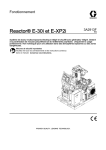
System description
FSO-11 and safety system components
Example figure of an FSO-11 safety functions module, ACS880 drive, safety PLC,
switches and buttons.
Safety PLC
system master
Safe stopping
Gate opening switch
FSO-11
Safety function requests
Prevention of unexpected
start-up
Key switch
Emergency stop
Stop button
Channel separation
The FSO-11 safety functions module is an option for ACS880 drives. Safe torque off
(STO) is a standard feature on ACS880 drives.
The FSO-11 does not operate the drive; it only monitors the actions of the drive and
commands safety functions to be executed. The request for safety functions can
come from an external safety system, for example a push button, safety PLC, or from
the FSO-11 internal fault. If the drive does not fulfill the commands of the FSO-11, the
FSO-11 will shut down the drive using the Safe torque off (STO) function.
Safety functions supported by the FSO-11 are presented in chapter Implemented
safety functions on page 33.
FSO-11 user's manual.book Page 29 Friday, October 19, 2012 10:30 AM
Overview 29
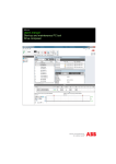
Layout
1
2
4
3
6
4b
4
5
7
8
9
4
No Description
1
24 V DC input connection
2
Safe torque off (STO) connection
3
Data connection
4, Mounting for drives with ZCU-11 control unit shown. Two mounting points on each side.
4b The screw fixed at 4b also grounds the enclosure of the FSO-11. Mounting points for
drives with other control units may vary.
5
FSO-11 grounding screw, grounds the electronics
6
FSO-11 status LEDs, see section Status LEDs on page 143.
7
Input / output status LEDs, one for each I/O connector (see 8). The LEDs are in two rows
above the corresponding two rows of I/O connectors. The LED is lit if the state of the
corresponding I/O is ON (24 V in the input or output). The data shown by LEDs is only
indicative and cannot be considered safe.
FSO-11 user's manual.book Page 30 Friday, October 19, 2012 10:30 AM
30 Overview
No Description
8
Input / output connections
• 4 redundant or 8 single digital inputs, or combinations of redundant and single inputs.
Possible redundant pairs: X113:1 & X114:1, X113:2 & X114:2, X113:3 & X114:3 and
X113:4 & X114:4.
• 3 redundant or 6 single digital outputs, or combinations of redundant and single
outputs. Possible redundant pairs: X113:7 & X114:7, X113:8 & X114:8 and X113:9 &
X114:9.
• two 24 V DC reference outputs with configurable diagnostic pulses.
9
Factory reset button (under the label)
Connections
The FSO-11 has several safety I/O’s for external safety devices, for example buttons,
gates and indicators. FSO-11 does not have ability to interface to an encoder.
When using the Safe brake control (SBC) function, the mechanical brake is controlled
by the FSO-11. For more information on the SBC, see section Safe brake control
(SBC) on page 42.
One FSO-11 is needed for each drive/inverter to be monitored.
Connection details are described in section Terminals on page 67.
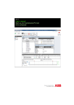
Type designation label
The type designation label is attached on the top of the FSO-11 module. An example
label and explanation of the label contents are shown below.
1
2
3
ABB OY FSO-11 SN: 41101B0001 CODE: 3AXD50000000005
3AXD5000000000541101B0001
3AXD5000000000541101B0001
3AXD5000000000541101B0001
RoHS
4
5
No Description
1 Type
2 Serial number of format MYYWWRXXXX, where
M:
Manufacturer
YY:
11, 12, … for 2011, 2012, …
WW:
01, 02, 03, … for week 1, week 2, week 3, …
R:
A, B, C, … for product revision number
XXXX:
Integer starting every week from 0001
3 ABB MRP code of the FSO-11 module
4 Combined ABB MRP code and serial number
5 RoHS mark
FSO-11 user's manual.book Page 31 Friday, October 19, 2012 10:30 AM
Overview 31
Operational characteristics
The FSO-11 monitors that the drive operates within the configured operating limits,
and if the limits are exceeded, activates the STO function within the response time.
Activation of the STO function removes the torque and, if configured, applies the
brake.
WARNING! The Safe torque off function does not disconnect the voltage of the
main and auxiliary circuits from the drive. See the warning on page 25.
Prevention of unexpected start-up is also handled by the FSO-11.
The supported functions are preprogrammed in the firmware; they cannot be
programmed in any way.
Authorized personnel configure the FSO-11 with the Drive composer pro PC tool. The
FSO-11 checks the authorization with a password before it is possible to edit the
FSO-11 parameters. Parameters are sent from the tool to the drive, and after the tool
has displayed the CRC values of the parameters, the user must validate the feedback
values.
The FSO-11 goes into the Fault state if it detects an internal fault during its
diagnostics tests.
FSO-11 user's manual.book Page 32 Friday, October 19, 2012 10:30 AM
32 Overview
FSO-11 user's manual.book Page 33 Friday, October 19, 2012 10:30 AM
Implemented safety functions 33
5
Implemented safety functions
Contents of this chapter
This chapter describes how the safety functions are implemented with the drive and
how they operate.
Safety functions
The FSO-11 supports the following safety functions:
Safety function
Safe torque off (STO)
Stop category
Information
Page
Stop category 0
Drive feature
40
Safe brake output
42
Stop category 1
Also with ramp monitoring
46
Safe stop emergency (SSE)
Configurable as STO or
SS1 with E-Stop ramp
50
Safely-limited speed (SLS)
Safely limited speed
55
Safe maximum speed (SMS)
Function permanently
on/off
57
Safe brake control (SBC)
Safe stop 1 (SS1)
FSO-11 user's manual.book Page 34 Friday, October 19, 2012 10:30 AM
34 Implemented safety functions
General
Acknowledgement
Acknowledgement can be configured to be manual or automatic, separately for the
start-up, STO (SSE and SS1 always end in STO) and SLS. In manual
acknowledgement there must be an acknowledgement button connected to the
FSO-11. In automatic acknowledgement the FSO-11 automatically acknowledges the
start-up, STO or SLS when this has completed successfully.
Acknowledgement cannot be performed if
•
safety function request is active
•
STO, SSE, SS1: safety function is not completed
•
SLS: speed is not below monitored limit.
All active safety functions that can be acknowledged are acknowledged with the
same acknowledgement.
The acknowledgement button is connected like a normal safety input. 24 V in the
input is the standby (negative) state and 0 V is the positive (acknowledge) state.
Button release allowed
0.3 s
3.0 s
ID
Description
A
Normal acknowledgement: The acknowledgement is recognized when the button is
released after pressing it; the system must detect both falling and rising edge changes
for successful acknowledgement triggering. The pressing time of the button must be
between 0.3 s…3.0 s.
B
Short low signals (less than 300 ms) are ignored.
C
Too long interruptions (signal low longer than 3 s) on the signal are ignored and a
warning message is generated to the drive. If there is something to acknowledge, it is
ignored and the user must press the acknowledgement button again. If there is nothing
to acknowledge, nothing happens and no errors are generated.
FSO-11 user's manual.book Page 35 Friday, October 19, 2012 10:30 AM
Implemented safety functions 35
Ramp monitoring
The ramp monitoring is configured with four parameters as described below.
Motor speed
D
Time
B
A
C
ID
Description
A
Ramp minimum time from the scaling speed to the zero speed = B - A. Specified for each
SARn ramp, n = 0…1 separately. For example for SAR0: parameter 104 SAR0 min ramp
time to zero.
B
Target time for the ramp down from the scaling speed to the zero speed. Specified for
each SARn ramp, n = 0…1 separately. For example for SAR0: parameter 103 SAR0
ramp time to zero.
C
Ramp maximum time from the scaling speed to the zero speed = B + C. Specified for
each SARn ramp, n = 0…1 separately. For example for SAR0: parameter 105 SAR0 max
ramp time to zero.
D
Initial allowed range for the SARn ramp. This is the time when the monitoring of the ramp
maximum time is started after the request. Common for all ramps SARn, n = 0…1.
Parameter 127 SAR initial allowed range.
Note: Maximum allowed time for a ramp is ten minutes from 1500 rpm to the zero speed.
FSO-11 user's manual.book Page 36 Friday, October 19, 2012 10:30 AM
36 Implemented safety functions
Function indication
The logic state of the output indication can be configured to be active low or active
high.
STO, SS1, SSE:
States of the configured and connected functions are indicated with FSO-11 digital
outputs when the function is started:
•
Stopping functions are always started immediately (first they monitor the time,
then possibly the ramp).
•
STO is indicated right away when the request is active (requested from input or by
diagnostics).
•
Ramp monitoring (SAR0 and SAR1, see section Configuring SAR on page 123) is
not indicated.
Digital output indication is removed when the function is completed.
•
SSE and SS1 are completed when the STO is acknowledged.
Stopping indication is activated when the stopping function has completed, but is not
yet acknowledged. There are separate indications for each stopping function STO,
SSE and SS1 (parameters 21 STO completed output, 31 SSE completed output and
40 SS1 completed output) and one common for all of them (parameter 6 Stop
completed output).
SLS:
•
SLS indication starts when the speed is in the monitored range, and indication is
removed when the function is completed or the monitored speed limit is exceeded
(this also causes the SLS to trip, that is, SSE is activated).
FSO-11 user's manual.book Page 37 Friday, October 19, 2012 10:30 AM
Implemented safety functions 37
States
The FSO-11 can be in one of the following states:
•
Power down:
STO active, power off (below 19 V)
•
Start-up:
STO active, power on (above 19 V), start-up checks performed
•
Configuration:
STO active, setting of parameters
•
Operational:
STO inactive, FSO-11 running
•
Safe:
STO active, FSO-11 running
•
Fault:
STO active, FSO-11 or communication fault detected.
Power down
(STO active)
Power
switch-off
Drive composer pro
Start-up
(STO active)
Drive composer pro
Operational
(STO inactive)
Drive composer pro
Configuration
(STO active)
Safe
(STO active)
Acknowledgement
Normal/obligatory transitions
Fault
(STO active)
Possible transitions
At power-up, the FSO-11 goes into the Start-up state; it performs start-up checks and,
according to the configuration, enters the Operational state either automatically or
after a manual acknowledgement.
FSO-11 user's manual.book Page 38 Friday, October 19, 2012 10:30 AM
38 Implemented safety functions
The Drive composer pro PC tool can request the Configuration state, when the
FSO-11 is in the Start-up, Operational, Safe or Fault state and the drive is in the
Torque off mode (not modulating). The FSO-11 exits the Configuration state into the
Start-up state either by a request from the Drive composer pro PC tool, or by
removing the power from the FSO-11 (through the Power down state).
In the Operational and Safe states, the FSO-11 can execute the safety functions.
Note: When the FSO-11 is in the Configuration state, the status/fault LED is lit red.
This requires the FSO-11 power down cycle to take the new parameters into use
before entering the Operational state.
If there is an internal fault, the FSO-11 enters the Fault state. The FSO-11 exits the
Fault state either by a request from the Drive composer pro PC tool into the
Configuration state, or by removing the power from the FSO-11 into the Power down
state. In the latter case, the FSO-11 starts again normally from the Start-up state after
restoring power.
When the FSO-11 is in the Power down, Start-up, Configuration, Safe or Fault state,
the STO is always active. When the FSO-11 is in the Operational state, the STO is
inactive.
Cascade
It is possible to cascade up to six FSO-11’s into a daisy-chain type network
(resembles somewhat an I/O master-follower system): If an FSO-11 triggers a
cascaded function, it passes the triggering information to the next FSO-11, which
triggers the next one, and so on, until the last FSO-11 again triggers the first one.
Acknowledgement
Automatic acknowledgement
G
ER EN
CY
EM
Emergency stop
STO P
FSO
FSO-11
FSO-11
Master
In
Out
Safety
function 1
In
In
Out
Out
Safety
Safety
function
function 2
In
Out
FSO
FSO-11
Follower
In
Out
Follower
In
Safety
Safety
function
function 1
In
Out
In
Out
Safety
Safety
function
function 2
In
Out
Out
Safety
Safety
function
function 1
In
Out
In
Out
In
Out
Safety
Safety
function
function 2
In
Out
FSO-11 user's manual.book Page 39 Friday, October 19, 2012 10:30 AM
Implemented safety functions 39
Cascade I/O connections must be set to use diagnostic pulsing.
One of the cascaded FSO-11’s must be configured as a master and the others as
followers.
All of the cascaded FSO-11’s must be set to use automatic acknowledgement. The
master may have an acknowledgement button, and the acknowledgement always
starts from the master.
Up to two safety functions may be cascaded, but it is highly recommended that one of
them is either SSE or STO.
If an FSO-11 activates STO for any reason, also the cascaded SSE output is
triggered.
FSO-11 user's manual.book Page 40 Friday, October 19, 2012 10:30 AM
40 Implemented safety functions
Safe torque off (STO)
STO base function
The STO brings the machine safely into a no-torque state and/or prevents it from
starting accidentally.
For more information on the STO base function in ACS880 drives, see the drive
Firmware manual.
The operation of the STO function is described in the time diagram and table below.
Motor
speed
STO time to zero speed
Time
STO request
Inactive
Active
STO state
STO state indication
STO completed
indication
ID
Description
A
Time to zero speed: Time from the STO activation to the moment when the
acknowledgment becomes allowed. Configured to the estimated time in which the motor
coasts to a stop from the maximum speed.
B
STO request removal allowed (shaded area). The STO request must be active for at
least 10 ms. The STO request must be removed before the acknowledgement is
accepted.
1
STO activated after the STO request has been received (for example from the I/O)
2
Acknowledgement is not allowed before the motor is presumably stopped.
3
After the time to zero speed (A) has elapsed, the STO is completed and the
acknowledgement is possible as soon as the STO request has been removed.
4
After the acknowledgement (manual or automatic), the STO is deactivated.
Note: Logic states of the STO state indication and STO completed indication signals
(outputs) are configurable.
Note: STO activation also activates the SSE state indication signal (output), if the
SSE is cascaded. See Safe stop emergency (SSE) on page 50 and Cascade on page
38.
FSO-11 user's manual.book Page 41 Friday, October 19, 2012 10:30 AM
Implemented safety functions 41
For configuration, see section How to configure STO on page 103 in chapter
Configuration.
FSO-11 user's manual.book Page 42 Friday, October 19, 2012 10:30 AM
42 Implemented safety functions
Safe brake control (SBC)
The SBC provides a safe output for controlling external (mechanical) brakes.
If the SBC is used, it is always combined with the STO, except in drive proof testing.
The SBC can be configured to be activated before, at the same time with, or after the
STO. The SBC and STO combination can also be configured to be activated below a
certain speed level while ramping down to the zero speed (see SS1 with speed limit
activated SBC on page 49 and SSE with speed limit activated SBC on page 54). In
that case, the SBC is activated at the configured speed level.
SBC after STO
The operation of the SBC after the STO is described in the time diagram and table
below.
STO time to zero speed
Motor
speed
SBC delay
Time
STO request
Inactive
Active
STO state
STO state indication
Inactive
Active
SBC control
STO completed
indication
ID
Description
A
SBC delay: Time from the STO activation to the moment when the mechanical brake is
active (on). Configurable.
B
Time to zero speed: Time from the STO activation to the moment when the
acknowledgment becomes allowed. Configured to the estimated time in which the motor
coasts to a stop from the maximum speed.
C
STO request removal allowed (shaded area). The STO request can be removed after a
minimum down time. It must be removed before the acknowledgement is accepted.
1
STO activated after the STO request has been received (for example from the I/O)
2
SBC is activated
3
Acknowledgement is not allowed before the motor is presumably stopped.
FSO-11 user's manual.book Page 43 Friday, October 19, 2012 10:30 AM
Implemented safety functions 43
ID
Description
4
After the time to zero speed (B) has elapsed, the STO is completed and the
acknowledgement is possible as soon as the STO request has been removed.
5
After the acknowledgement (manual or automatic), the STO and SBC are deactivated,
and the control is given back to the drive, which controls the brake from now on.
Note: Logic states of the STO state indication and STO completed indication signals
(outputs) are configurable.
Note: STO activation also activates the SSE state indication signal (output), if the
SSE is cascaded. See Safe stop emergency (SSE) on page 50 and Cascade on page
38.
It is possible to set the SBC delay so that the SBC is activated while the motor is still
rotating, as in the example above.
For configuration, see section How to configure SBC after STO on page 105 in
chapter Configuration.
FSO-11 user's manual.book Page 44 Friday, October 19, 2012 10:30 AM
44 Implemented safety functions
SBC before STO
The target of the 'negative' SBC delay is to have the mechanical brake closed just
before (or at the same moment as) the STO is opened.
The operation of the SBC before the STO is described in the time diagram and table
below.
Motor speed
STO time to zero speed
SBC delay < 0
Time
STO request
Active
Inactive
Active
STO state
STO state indication
SBC control
STO completed indication
ID
Description
A
SBC delay: Time from the STO activation to the moment when the mechanical brake is
active (on). Value negative.
B
Time to zero speed: Time from the STO activation to the moment when the
acknowledgment becomes allowed. Configured to the estimated time in which the motor
coasts to a stop from the maximum speed.
C
STO request removal allowed (shaded area). The STO request can be removed after a
minimum down time. It must be removed before the acknowledgement is accepted.
1
SBC activated after the STO request has been received (for example from the I/O)
2
Braking has ended and the motor is at a standstill.
3
STO activated after the SBC delay (A) has elapsed.
4
After the time to zero speed (B) has elapsed, the acknowledgement is possible as soon
as the STO request has been removed.
5
After the acknowledgement (manual or automatic), the STO and SBC are deactivated,
and the control is given back to the drive, which controls the brake from now on.
Note: Logic states of the STO state indication and STO completed indication signals
(outputs) are configurable.
FSO-11 user's manual.book Page 45 Friday, October 19, 2012 10:30 AM
Implemented safety functions 45
Note: STO activation also activates the SSE state indication signal (output), if the
SSE is cascaded. See Safe stop emergency (SSE) on page 50 and Cascade on page
38.
For configuration, see section How to configure SBC before STO on page 107 in
chapter Configuration.
FSO-11 user's manual.book Page 46 Friday, October 19, 2012 10:30 AM
46 Implemented safety functions
Safe stop 1 (SS1)
The SS1 stops the motor safely, initiating the STO function below a specified speed
or after a specified time limit.
SS1 with time monitoring
Motor speed
SS1 delay for STO
STO time to zero speed
Zero
speed
Time
SS1 request
Inactive
Active
STO state
STO state indication
SS1 state
SS1 state indication
SS1 completed indication
ID
Description
A
SS1 delay for STO: Time after which the STO is activated regardless of the speed.
B
Time to zero speed: Time from the STO activation to the moment when acknowledgment
becomes allowed. Configured to the estimated time in which the motor coasts to a stop
from the maximum speed. Relevant only if 3b occurs.
C
Zero speed: Speed limit for activating the STO
D
SS1 request removal allowed (shaded area). The SS1 request can be removed after a
minimum down time. It must be removed before the acknowledgement is accepted.
E
Safety function response time
1
SS1 request received (for example from the I/O)
2
After the safety function response time, ramping down is started.
3
Speed goes below the defined zero speed limit, and the STO is activated.
3b
If the drive has not ramped down fast enough when the delay for STO (A) has elapsed,
the STO is activated now and the time to zero speed (B) is started.
4
After the acknowledgement (manual or automatic), the STO and SS1 are deactivated.
4b
If the drive had not ramped down fast enough at 3b, acknowledgement would become
allowed now.
FSO-11 user's manual.book Page 47 Friday, October 19, 2012 10:30 AM
Implemented safety functions 47
Note: Logic states of the STO state indication, SS1 state indication and SS1
completed indication signals (output) are configurable.
Note: SS1 monitoring is started immediately after the SS1 request is received.
For configuration, see section How to configure SS1 with time monitoring on page
109 in chapter Configuration.
FSO-11 user's manual.book Page 48 Friday, October 19, 2012 10:30 AM
48 Implemented safety functions
SS1 with ramp monitoring
Motor speed
STO time to zero speed
Zero
speed
Time
SS1 request
Inactive
Active
STO state
STO state indication
SS1 state
SS1 state indication
SS1 completed indication
ID
Description
A
Time to zero speed: Time from the STO activation to the moment when the
acknowledgment becomes allowed. Configured to the estimated time in which the motor
coasts to a stop from the maximum speed. Relevant only if 2b occurs.
B
Zero speed: Speed limit for activating the STO.
C
SS1 request removal allowed (shaded area). The SS1 request can be removed after a
minimum down time. It must be removed before the acknowledgement is accepted.
D
Safety function response time
1
SS1 request received (for example from the I/O)
2
After the safety function response time, ramping down with SAR1 monitoring is started.
2b
If the drive has not followed the ramp, the STO is activated now and the time to zero
speed (A) is started.
3
Speed goes below the defined zero limit, the SAR monitoring is stopped and the STO is
activated
4
After acknowledgement (manual or automatic), the STO and SS1 are deactivated, and
the control is given back to the drive, which is allowed to modulate again.
4b
If the drive had not followed the ramp at 2b, acknowledgement would become allowed
now.
Note: Logic states of the STO state indication, SS1 state indication and SS1
completed indication signals (output) are configurable.
For configuration, see section How to configure SS1 with ramp monitoring on page
111 in chapter Configuration.
FSO-11 user's manual.book Page 49 Friday, October 19, 2012 10:30 AM
Implemented safety functions 49
SS1 with speed limit activated SBC
Motor speed
SBC
speed
Zero
speed
Time
SS1 request
Inactive
Active
STO state
STO state indication
SBC control
SS1 state
SS1 state indication
SS1 completed indication
ID.
Description
A
SBC speed: Speed below which the brake is activated while ramping
B
Zero speed: Speed limit for activating the STO
C
SS1 request removal allowed (shaded area). The SS1 request can be removed after a
minimum down time. It must be removed before the acknowledgement is accepted.
D
Safety function response time
1
SS1 is requested (for example from the I/O).
2
After the safety function response time, ramping down with SAR0/SAR1 monitoring is
started.
3
Speed is below the SBC speed; the SAR monitoring is stopped and the brake is
activated
4
STO is activated after brake activation.
5
After acknowledgement (manual or automatic), the STO and the brake are deactivated,
and the control is given back to the drive, which is allowed to modulate again.
Note: Logic states of the STO state indication, SS1 state indication and SS1
completed indication signals (output) are configurable.
For configuration, see section How to configure SS1 with speed limit activated SBC
on page 113 in chapter Configuration
FSO-11 user's manual.book Page 50 Friday, October 19, 2012 10:30 AM
50 Implemented safety functions
Safe stop emergency (SSE)
The SSE can be configured to execute either the STO, or the SS1 with emergency
ramp.
The behavior of the SSE with STO is identical to the pure STO, except that different
timing parameters are used.
The behavior of the SSE with SS1 with emergency ramp is identical to the SS1 with
ramp monitoring.
For configuration, see section How to configure SSE on page 115 in chapter
Configuration.
The operation of the SSE function with STO is described in the time diagram and
table below.
Motor
speed
SSE time to zero speed with STO
Time
SSE request
Active
Active
STO state
STO state indication
SSE state
SSE state indication
SSE completed
indication
ID
Description
A
SSE time to zero speed with STO: Time from the STO activation to the moment when the
acknowledgment becomes allowed. Configured to the estimated time in which the motor
coasts to a stop from the maximum speed.
B
SSE request removal allowed (shaded area). The SSE request can be removed after a
minimum down time. It must be removed before the acknowledgement is accepted.
1
STO activated after the SSE request has been received (for example from the I/O).
2
Acknowledgment not yet allowed before the motor is presumably stopped.
3
After the time to zero speed (A) has elapsed, the acknowledgement is possible as soon
as the STO request has been removed.
4
After the acknowledgement, the STO and SSE are deactivated, and the control is given
back to the drive.
FSO-11 user's manual.book Page 51 Friday, October 19, 2012 10:30 AM
Implemented safety functions 51
Note: Logic states of the STO state indication signal, SSE state indication and SSE
completed indication signals (output) are configurable.
FSO-11 user's manual.book Page 52 Friday, October 19, 2012 10:30 AM
52 Implemented safety functions
SSE with time monitoring
Motor speed
SSE delay for STO
STO time to zero speed
Zero
speed
Time
SSE request
Inactive
Active
Active
STO state
STO state indication
SSE state
SSE state indication
SSE completed indication
ID
Description
A
SSE delay for STO: Time after which the STO is activated regardless of the speed.
B
STO time to zero speed: Time from the STO activation to the moment when
acknowledgment becomes allowed. Configured to the estimated time in which the motor
coasts to a stop from the maximum speed. Relevant only if 3b occurs.
C
Zero speed: Speed limit for activating the STO
D
SSE request removal allowed. (shaded area) The SSE request can be removed after a
minimum down time. It must be removed before the acknowledgement is accepted.
E
Safety function response time
1
SSE request received (for example from the I/O)
2
Ramping down is started.
3
Speed goes below the defined zero speed limit and the STO is activated.
3b
If the drive has not ramped down fast enough when the delay for STO (A) has elapsed,
the STO is activated now and the time to zero speed (B) is started.
4
After acknowledgement (manual or automatic), the STO and SSE are deactivated.
4b
If the drive had not ramped down fast enough at 3b, acknowledgement would become
allowed now.
Note: Logic states of the STO state indication signal, SSE state indication and SSE
completed indication signals (output) are configurable.
Note: SSE monitoring is started immediately after the SSE request is received.
FSO-11 user's manual.book Page 53 Friday, October 19, 2012 10:30 AM
Implemented safety functions 53
For configuration, see section How to configure SSE with time monitoring on page
117 in chapter Configuration.
SSE with ramp monitoring
Motor speed
STO time to zero speed
Zero
speed
Time
SSE request
Inactive
Active
STO state
STO state indication
Active
SSE state
SSE state indication
SSE completed indication
ID
Description
A
Time to zero speed. Time from the STO activation to the moment when the
acknowledgment becomes allowed. Configured to the estimated time in which the motor
coasts to a stop from the maximum speed. Relevant only if 2b occurs.
B
Zero speed: Speed limit for activating the STO.
C
SSE request removal allowed (shaded area). The SSE request can be removed after a
minimum down time. It must be removed before the acknowledgement is accepted.
1
SSE request received (for example from the I/O)
2
After the safety function response time, ramping down with SAR0 monitoring is started.
2b
If the drive has not followed the ramp, the STO is activated now and the time to zero
speed (A) is started.
3
Speed goes below the defined zero limit, the SAR monitoring is stopped and the STO is
activated.
4
After the acknowledgement (manual or automatic), the STO and SSE are deactivated,
and the control is given back to the drive, which is allowed to modulate again.
4b
If the drive had not followed the ramp at 2b, acknowledgement would become allowed
now.
Note: Logic states of the STO state indication signal, SSE state indication and SSE
completed indication signals (output) are configurable.
FSO-11 user's manual.book Page 54 Friday, October 19, 2012 10:30 AM
54 Implemented safety functions
For configuration, see section How to configure SSE with ramp monitoring on page
119 in chapter Configuration.
SSE with speed limit activated SBC
Motor speed
A
SBC
speed
Zero
speed
Time
SSE request
Inactive
Active
STO state
STO state indication
SBC control
SSE state
SSE state indication
SSE completed indication
ID.
Description
A
SBC speed: Speed below which the brake is activated while ramping
B
Zero speed: Speed limit for activating the STO
C
SSE request removal allowed (shaded area). The SSE request can be removed after a
minimum down time. It must be removed before the acknowledgement is accepted.
1
SSE is requested (for example from the I/O).
2
Ramping down with SAR0 monitoring is started.
3
Speed is below the SBC speed; the SAR monitoring is stopped and the brake is
activated
4
STO is activated after the brake activation.
5
After the acknowledgement (manual or automatic), the STO and the brake are
deactivated, and the control is given back to the drive.
Note: Logic states of the STO state indication signal, SSE state indication and SSE
completed indication signals (output) are configurable.
For configuration, see section How to configure SSE with speed limit activated SBC
on page 121 in chapter Configuration
FSO-11 user's manual.book Page 55 Friday, October 19, 2012 10:30 AM
Implemented safety functions 55
Safely-limited speed (SLS)
The SLS prevents the motor from exceeding the specified speed limit.
SLS with speed below monitored speed
This applies to both time and ramp monitoring.
Motor speed
Zero
speed
Time
SLS request
Inactive
ID
Active
SLS state
SLS state indication
Description
A
SLS upper trip limit
B
SLS request removal allowed (shaded area). The SLS request can be removed after a
minimum down time. It must be removed before the acknowledgement is accepted.
1
SLS is requested, the speed is below the SLS upper trip limit and so the monitoring is
started.
2
SLS request is removed, but the monitoring is still on if manual acknowledgement is
configured. If automatic acknowledgement is configured, the monitoring is also ended.
3
SLS is acknowledged (manually) and the monitoring is ended.
Note: Logic state of the SLS state indication signal (output) is configurable.
For configuration, see section Configuring SLS on page 124 in chapter Configuration.
FSO-11 user's manual.book Page 56 Friday, October 19, 2012 10:30 AM
56 Implemented safety functions
SLS with speed above monitored speed
This applies to time monitoring.
Motor speed
SLS time delay
Zero
speed
Time
SLS request
Inactive
Active
SLS state
SLS state indication
ID
Description
A
SLS upper trip limit
B
SLS request removal allowed (shaded area). The SLS request can be removed after a
minimum down time. It must be removed before the acknowledgement is accepted.
C
SLS time delay: Delay for forcing to start SLS monitoring when time monitoring is in use.
D
Safety function response time
1
SLS is requested but the speed is above the SLS upper trip limit.
2
The drive starts to ramp down. If ramp monitoring were in use, the SAR1 ramp would be
used from here until the speed would go below the SLS upper trip limit. If time monitoring
were in use, the ramp defined by the drive parameters would be used from here until the
speed would go below the SLS upper trip limit.
3
Speed is below the SLS upper trip limit and the monitoring of the SLS is started.
4
The FSO-11 would start the SLS monitoring at the latest here, that is, after the SLS time
delay has elapsed.
5
SLS request is removed, but the monitoring is still on.
6
SLS is acknowledged (manually or automatically) and the monitoring is ended. When the
SLS is removed, the drive continues with the previously set speed.
Note: Logic state of the SLS state indication signal (output) is configurable.
Note: If the SLS monitoring must be activated immediately, regardless of the current
speed, time monitoring with zero time must be used instead of ramp monitoring.
For configuration, see section Configuring SLS on page 124 in chapter Configuration.
FSO-11 user's manual.book Page 57 Friday, October 19, 2012 10:30 AM
Implemented safety functions 57
Safe maximum speed (SMS)
SMS is used to protect the machine from too high speeds/frequencies. It can only be
configured to be on or off. The upper and lower limits can be configured separately.
If the speed should reach the maximum limit, the SSE would be activated.
Motor speed
Time
ID
Description
A
SMS maximum speed
B
SMS minimum speed
For configuration, see section Configuring SMS on page 130 in chapter
Configuration.
FSO-11 user's manual.book Page 58 Friday, October 19, 2012 10:30 AM
58 Implemented safety functions
FSO-11 user's manual.book Page 59 Friday, October 19, 2012 10:30 AM
Planning for installation 59
6
Planning for installation
Contents of this chapter
This chapter gives instructions and references to instructions in other manuals for
planning the safety system installation, as well as the requirements for installation in
the applicable safety standards.
Requirements for designers and installers
•
Designers and installers must be trained to understand the requirements and
principles of designing and installing safety-related systems.
•
Designers and maintainers must be trained to understand the causes and
consequences of Common Cause Failures (CCF). See the checklist for the
appropriate standard in section Common cause failure (CCF) checklists on page
72.
Mechanical installation
Installation site
The subsystem elements must always be likely to operate within the range of
temperature, humidity, corrosion, dust, vibration, etc. over which it has been tested,
without the use of external environmental control.
The FSO-11 module must only be used in an environment where no conductive dust
or contaminants are present. One way to ensure proper protection against
contamination is to use the FSO-11 in at least an IP 54 enclosure. For further
information on environmental limits of the FSO-11, see chapter Planning the
mechanical installation in the drive Hardware manual.
FSO-11 user's manual.book Page 60 Friday, October 19, 2012 10:30 AM
60 Planning for installation
WARNING! Operating the drive system with a safety module in environmental
conditions that are outside of the specified ranges for the safety module may
result in losing the safety function.
Electrical installation
General requirements
Electrical installation of the safety system must be performed according to the
practices outlined in chapter Planning the electrical installation in the drive Hardware
manual.
Reading chapter Installation checklists on page 71 provides additional advice for the
planning.
All wiring must be well protected, routed and clamped where practicable.
When installing cabling it must be assured that there is no pulling or pinching on the
cables.
Connections
Inputs and outputs
To design the safety system architecture and select components to be used, it is
essential to read and understand the different architecture options (for example single
channel / redundancy).
Single inputs can be connected to any connection X113:1…4 or X114:1…4, and they
can use either one of the test pulses X113:10 and X114:10.
Redundant inputs must be connected so that one input is connected to X113:n and
uses test pulse X113:10, and the other is connected to X114:n and uses test pulse
X114:10 (n= 1…4; the same for both inputs).
TP2 X114:10
Test pulse 1
TP1 X113:10
Test pulse 2
DI1 X113:n, n = 1…4
Digital input 1
DI2 X114:n, n = 1…4
Digital input 2
FSO-11 user's manual.book Page 61 Friday, October 19, 2012 10:30 AM
Planning for installation 61
Note: Calculation software can be used to assist in selecting the appropriate
architecture that will meet the safety integrity requirements for a particular application.
Power supply connection/cables
The system must be protected against over-voltage and over-current.
The length of the cabling between the FSO-11 and its power supply must be
three meters or shorter, or a sufficiently low interference level must be otherwise
guaranteed.
Note: The 24 V DC power supply should be equipped with a supply disconnecting
device to enable the easy start-up of the FSO-11.
Ensuring the EMC compatibility
The system must only be used in the EMC environment it is designed for, or
necessary mitigations must be applied.
Selecting control cables
For the control cables to on-field devices, it is recommended that shielded cabling is
used. Double-shielded cable is the best alternative for low-voltage digital signals but
single-shielded twisted multipair cable is also usable.
See Control connection data on page 151 and chapter Planning the electrical
installation in the drive Hardware manual.
Routing the cables
See chapter Planning the electrical installation in the drive Hardware manual. Follow
especially the rules below:
•
When using redundant signaling, take care to avoid common cause failures in the
cables. This can be done by routing the two channels through two well-apart
routes, or by protecting the cabling appropriately, for example by using doubleshielded cables.
•
Never mix 24V-level signals with non-ELV-signals or power feeds in the same
cable.
•
Safety Related Electronic Control System (SRECS) signal cables for the
individual channels must be routed separately from the other channels at all
positions or sufficiently shielded.
•
SRECS signal and electrical energy power cables must be separated at all
positions or sufficiently shielded.
•
Cross-connection between the channels of the subsystem must be prevented.
•
Signal paths must be physically separated (for example separation in wiring).
FSO-11 user's manual.book Page 62 Friday, October 19, 2012 10:30 AM
62 Planning for installation
Standard function and wiring examples
Passive switch
Examples:
•
Limit switch
•
Emergency stop button
X113
X114
TP
10
9
DO 8
7
6
GND
5
4
3
DI
2
1
Physical separation of the
different channels or appropriate
cable protection (eg. doubleshielding)
Channel separation
Diagnostic pulses
Relay / contactor output with feedback
Safety relays must have positive driven contacts. Contactors must have mechanically
linked contacts.
Examples:
•
Brake control
•
Door/gate unlock
X113
X114
TP
10
9
DO 8
7
6
GND
5
4
3
DI
2
1
Diagnostic pulses
FSO-11 user's manual.book Page 63 Friday, October 19, 2012 10:30 AM
Planning for installation 63
Active sensors / input signals from solid state devices
Examples:
•
PLC 24 V DC PNP
•
Light curtain OSSD
X113
X114
Physical separation of the different channels
or appropriate cable protection (eg. doubleshielding)
TP
10
9
DO 8
7
6
GND
5
4
3
DI
2
1
CH 2 24 V DC
PNP
outputs
CH 1
Diagnostic pulses from an
active sensor must not be
overlapping.
+
COM /
GND
GND
Channel separation
Outputs to solid state devices
Example:
•
PLC 24 V DC NPN
X113
TP
10
9
DO 8
7
6
GND
5
4
3
DI
2
1
X114
Physical separation of different the channels
or appropriate cable protection (eg. doubleshielding)
CH 1 24 V DC
NPN
CH 2 inputs
+
COM /
GND
GND
Channel separation
Diagnostic pulses
FSO-11 user's manual.book Page 64 Friday, October 19, 2012 10:30 AM
64 Planning for installation
Cascade
Example:
X114
E-stop
button
X113
1
2
DI
3
4
5 GND
6
7
8 DO
9
10 TP
ACK
button
Module 1
(cascade
master)
Common
GND
Physical separation of the different
channels or appropriate cable protection
(eg. double-shielding)
X114
X113
Module 2
1
2
DI
3
4
5 GND
6
7
8 DO
9
10 TP
Common
GND
X114
X113
1
2
DI
3
4
5 GND
6
7
8 DO
9
10 TP
Channel separation
Diagnostic pulses
Common
GND
Module 3
FSO-11 user's manual.book Page 65 Friday, October 19, 2012 10:30 AM
Installation 65
7
Installation
Contents of this chapter
This chapter gives examples of how to connect the FSO-11 module to the ACS880.
WARNING! The supply voltage for FSO-11 is 24 V DC. If the FSO-11 is
supplied with a higher voltage, for example 230 V or 115 V, it is damaged and
needs to be replaced.
WARNING! For connecting the FSO-11 module to the drive, only use wire kits
delivered by ABB.
FSO-11 user's manual.book Page 66 Friday, October 19, 2012 10:30 AM
66 Installation
Mechanical installation
If you have ordered the FSO-11 module option with the drive, it is delivered with the
FSO-11 already installed and the FSO-11 data cable connected, so you can go
directly to section Electrical installation on page 67.
If you have ordered the FSO-11 module option separately, it is delivered in its own
package. Install the FSO-11 mechanically on the drive as described in chapter
Mechanical installation in the drive Hardware manual.
Depending on the type of the drive, the location of the module may be for example
one of the following:
FSO-11 user's manual.book Page 67 Friday, October 19, 2012 10:30 AM
Installation 67
Electrical installation
Terminals
The connections are shown in the figure below.
X110:
DATA Data connection to drive
control unit
X111:
1 STO
2 STO
3 STO
4 STO
STO 24 V
STO ground
STO1LO drive internal signal
STO2LO drive internal signal
X112:
1 POWER 24 V
2 POWER 0 V
B
A
B
A
B
A
Electronics grounding screw
Enclosure grounding screw, at one of the
mounting points, depending on the drive
type
X113:
1 DI
2 DI
3 DI
4 DI
5 GND
6 GND
7 DO
8 DO
9 DO
10 TP
Channel 1 digital input 1
Channel 1 digital input 2
Channel 1 digital input 3
Channel 1 digital input 4
Signal ground
Signal ground
Channel 1 digital output 1
Channel 1 digital output 2
Channel 1 digital output 3
Channel 1 test pulse out
X114:
1 DI
2 DI
3 DI
4 DI
5 GND
6 GND
7 DO
8 DO
9 DO
10 TP
Channel 2 digital input 1
Channel 2 digital input 2
Channel 2 digital input 3
Channel 2 digital input 4
Signal ground
Signal ground
Channel 2 digital output 1
Channel 2 digital output 2
Channel 2 digital output 3
Channel 2 test pulse out
FSO-11 user's manual.book Page 68 Friday, October 19, 2012 10:30 AM
68 Installation
Connection procedure
Depending on the type of the drive, the location of the module may be for example
one of the following shown in the figures below.
1. Ensure that the FSO-11 electronics grounding screw is properly tightened.
2. Ensure that the FSO-11 enclosure grounding screw is properly tightened.
1
2
1
2
3. Ensure that the FSO-11 data cable (terminal X110) is connected to the drive.
3
3
FSO-11 user's manual.book Page 69 Friday, October 19, 2012 10:30 AM
Installation 69
4. Connect the supplied four-wire cable to the FSO-11 terminal X111 and plug the
other end of the cable to the drive STO connection. Use the tightening torque of
0.24 Nm (2.1 lbf·in) for the FSO-11 terminals.
5. Connect the digital inputs, digital outputs, test pulses and ground at the FSO-11
terminals X113 and X114 according to the application. Use the tightening torque
of 0.24 Nm (2.1 lbf·in).
5
4
4
5
FSO-11 user's manual.book Page 70 Friday, October 19, 2012 10:30 AM
70 Installation
6. Connect the FSO-11 power terminals X112. Use the tightening torque of 0.24 Nm
(2.1 lbf·in) for the FSO-11 terminals.
6
6
FSO-11 user's manual.book Page 71 Friday, October 19, 2012 10:30 AM
Installation checklists 71
8
Installation checklists
Contents of this chapter
This chapter contains a checklist for checking the mechanical and electrical
installation of the FSO-11 module and refers to common cause failure checklists in
standards.
Checklists
Check the mechanical and electrical installation of the FSO-11 before start-up. Go
through the checklists below together with another person. Read chapter Safety on
page 11 before you work on the safety system.
FSO-11 user's manual.book Page 72 Friday, October 19, 2012 10:30 AM
72 Installation checklists
General checklist
Check
MECHANICAL INSTALLATION (See Planning for installation and Installation: Mechanical
installation)
The ambient operating conditions are within the allowed range.
The module is fastened properly.
ELECTRICAL INSTALLATION (See Planning for installation and Installation: Electrical
installation)
The drive and the module are properly grounded to the same potential.
If a PELV power supply is used, its ground has to be in the same potential as the drive
ground.
Appropriate supply (input power) fuses are installed.
Signal wiring between the drive and the module is routed separately from the power
supply wiring and high power cables (drive supply and motor cabling).
Signal wiring is appropriately clamped, marked and protected.
Common cause failure (CCF) checklists
Check measures against common cause failures (CCF). There is one checklist in
EN ISO 13849-1 and another in EN 62061. The checklists are useful for both the
planning of the installation and the actual installation.
FSO-11 user's manual.book Page 73 Friday, October 19, 2012 10:30 AM
Configuration 73
9
Configuration
Contents of this chapter
This chapter describes the password usage, outlines the configuration process, lists
the FSO-11 parameters and gives examples of how to configure the FSO-11 to
implement each safety function as described in chapter Implemented safety functions
on page 33.
Password
Note: You need a password to be able to copy the configuration to the FSO-11.
The configuration is protected with a password. You need a password to be able to
upload the parameters from the drive to the FSO-11 and download the modified
parameters from your PC to the FSO-11.
The password is set to “12345678” at the factory. The password must contain 4…8
digits. When you change it, do not forget the new password; otherwise you have to do
a factory reset to the FSO-11 which clears the configuration and resets the
parameters to the factory defaults. The password is reset to the default “12345678”.
Factory defaults are not a valid configuration, so you have to reconfigure the FSO-11
or download the configuration to the FSO-11.
Configuring the FSO-11
The FSO-11 parameters are set with the Drive composer pro PC tool. The names of
the FSO-11 parameters and parameter settings are shown in the manual as they
appear on the screen when using the tool. See the Drive composer PC tool user's
manual (3AUA0000094606 [English]) for instructions on using the tool.
Note: Only trained persons are allowed to configure safety functions.
FSO-11 user's manual.book Page 74 Friday, October 19, 2012 10:30 AM
74 Configuration
Note: Configuration is only possible when the motor is stopped and the drive is not
modulating.
Note: After you initially start-up the FSO-11 and also after you later modify any
application parameters or the configuration, you must check the safety of the entire
system by doing a verification according to the system safety verification plan and by
doing a validation of the correct operation of the safety application. See Verification
and validation on page 133.
When configuring the FSO-11, follow the steps shown in the diagram below:
Configuration
1
2
3
Plan configuration
Configure
Print, sign and file the configuration report
Do commissioning tests
Print, sign and file the commissioning report
1. Plan the configuration (parameter values) according to the safety system,
installation, wiring, etc.
2. Set the parameter values in the Drive composer pro PC tool.
a. Start the drive and stop the motor.
b. Connect your PC to the drive, start the tool and select Safety settings.
c. Open the parameters for setting in one of these two ways:
•
First start: Upload the parameters from the FSO-11 to the tool (button
Upload from FSO). Password is required.
•
Existing configuration: Open the configuration file (button Open safety
file).
FSO-11 user's manual.book Page 75 Friday, October 19, 2012 10:30 AM
Configuration 75
d. Set the safety function parameters.
•
General parameters: Start from the general parameters. Check at least
that the motor parameters are correct.
•
I/O: Check that the I/O parameters are set according to the installation
(wiring) plan. Remove diagnostic pulsing from any unused I/O. Check
possible safety relays and cascade connections
Note: If there are only passive devices (for example switches) connected,
do not make any changes to the diagnostic pulsing. However, if there is an
active device (for example a PLC or light curtain), check if it can use the
same diagnostic pulsing as the FSO-11; if not, tune the FSO-11 diagnostic
pulsing.
•
Safety functions: You must at least configure the STO, regardless of what
you use the FSO-11 for or which safety functions you are using. The STO
is essential for the FSO-11 to be able to make the system safe; all other
functions are just for monitoring the drive
e. After configuring all functions, do these two steps:
f.
•
Save the configuration to your PC (button Save safety file).
•
Download the configuration to the FSO-11 (button Download to FSO and
validate). Password is required.
After downloading, the FSO-11 and the tool validate the configuration, and the
tool asks you to confirm the validation.
g. The tool then automatically reboots the drive to take the changes in use.
h. If necessary, change the password to protect the settings (button Change
password). Password is required.
Note: The motor must be stopped if you change the password.
3. After validation, print the report from the configuration, including all the values of
the parameters and CRC. Sign and file the report according to your safety
management plan.
Note: If you want to clear the configuration and start configuration again from the
factory setup, do a factory reset. See section Drive firmware update on page 149.
FSO-11 user's manual.book Page 76 Friday, October 19, 2012 10:30 AM
76 Configuration
FSO-11 parameters
The following table lists the FSO-11 parameters: The parameter row shows
parameter number, name, description and default value. The subsequent rows show
the parameter value range or names, descriptions and numerical values of the
selectable named alternatives.
For additional information on parameters and their settings, see the drive Firmware
manual.
Note: When the encoderless mode is used, the unit of the speed parameters is rpm.
Note: When the FSO-11 is connected to the drive, you must set drive parameter
31.22 STO indication run/stop to value 3, 4 or 5. This setting prevents the drive from
making a fault every time the FSO-11 opens the STO. The FSO-11 will generate the
necessary faults to the drive event system.
Note: If Time is selected for the method of SLS activation monitoring, the ramp used
is defined by the drive ramp parameters.
No
Name/Value
200 Safety
6 Stop completed
output
None
Description
Default /
sel. value
Safety related parameters
Digital output indicating completion of any stop. Active None
if STO, SSE or SS1 is completed.
No input connected
0
DO X113:7 & X114:7 Redundant output X113:7 & X114:7
1
DO X113:8 & X114:8 Redundant output X113:8 & X114:8
2
DO X113:9 & X114:9 Redundant output X113:9 & X114:9
3
DO X113:7
Single output X113:7
4
DO X113:8
Single output X113:8
5
DO X113:9
Single output X113:9
6
DO X114:7
Single output X114:7
7
DO X114:8
Single output X114:8
8
DO X114:9
Single output X114:9
9
Digital input connected to the STO primary input
DI X113:1 &
X114:1
No input connected
0
7 STO input A
None
DI X113:1 & X114:1 Redundant input X113:1 & X114:1
1
DI X113:2 & X114:2 Redundant input X113:2 & X114:2
2
DI X113:3 & X114:3 Redundant input X113:3 & X114:3
3
DI X113:4 & X114:4 Redundant input X113:4 & X114:4
4
DI X113:1
Single input X113:1
5
DI X113:2
Single input X113:2
6
DI X113:3
Single input X113:3
7
DI X113:4
Single input X113:4
8
FSO-11 user's manual.book Page 77 Friday, October 19, 2012 10:30 AM
Configuration 77
No
Name/Value
Description
Default /
sel. value
DI X114:1
Single input X114:1
9
DI X114:2
Single input X114:2
10
DI X114:3
Single input X114:3
11
DI X114:4
Single input X114:4
12
Digital input connected to the STO secondary input.
Secondary input is mostly used for the cascade
connection.
None
8 STO input B
See parameters 188 Cascade A and 189 Cascade B.
None
No input connected
0
DI X113:1 & X114:1 Redundant input X113:1 & X114:1
1
DI X113:2 & X114:2 Redundant input X113:2 & X114:2
2
DI X113:3 & X114:3 Redundant input X113:3 & X114:3
3
DI X113:4 & X114:4 Redundant input X113:4 & X114:4
4
DI X113:1
Single input X113:1
5
DI X113:2
Single input X113:2
6
DI X113:3
Single input X113:3
7
DI X113:4
Single input X113:4
8
DI X114:1
Single input X114:1
9
DI X114:2
Single input X114:2
10
DI X114:3
Single input X114:3
11
DI X114:4
Single input X114:4
12
Time after which the restart is allowed after the STO
2000 ms
9 Restart delay after
STO
0…3,600,000 ms
11 STO SBC usage
Time
Brake usage is always coupled with the STO. This
parameter defines how.
None
None
No brake
0
Delayed brake
Time controlled brake
1
Brake usage delay relative to the STO. Negative
value means that the brake is activated before STO
activation. Note: Mechanical brake delays must be
included in here.
3,600,000
ms
12 STO SBC delay
-1000…
3,600,000 ms
15 SSE/SS1 SBC
speed
0.0…1000.0 rpm
16 SBC output
None
Time
Absolute speed below which the brake is activated
while ramping. If the value is 0.0 rpm, this feature is
not in use.
0.0 rpm
Speed
Digital output connected to the SBC output (brake
relays)
None
No output connected
0
DO X113:7 & X114:7 Redundant output X113:7 & X114:7
1
FSO-11 user's manual.book Page 78 Friday, October 19, 2012 10:30 AM
78 Configuration
No
Name/Value
Description
DO X113:8 & X114:8 Redundant output X113:8 & X114:8
DO X113:9 & X114:9 Redundant output X113:9 & X114:9
17 SBC feedback type
Default /
sel. value
2
3
Where the SBC gets the feedback from
Safety relay
feedback
Safety relay
feedback
Feedback is connected to a safety relay (inverted
state compared with the outputs)
0
Mechanical brake
feedback
Feedback is connected to a mechanical brake (same 1
state as the outputs, but delayed)
18 SBC feedback
action
STO
Action taken when there is a problem on the SBC
feedback
STO
STO activated
0
STO acknowledgement method
Manual
Manual
Manual acknowledgement after the removal of
requests
0
Automatic
Automatic acknowledgement after the removal of
requests
1
19 STO
acknowledgement
20 STO output
None
Digital output indicating activity of the STO
None
No output connected
0
DO X113:7 & X114:7 Redundant output X113:7 & X114:7
1
DO X113:8 & X114:8 Redundant output X113:8 & X114:8
2
DO X113:9 & X114:9 Redundant output X113:9 & X114:9
3
DO X113:7
Single output X113:7
4
DO X113:8
Single output X113:8
5
DO X113:9
Single output X113:9
6
DO X114:7
Single output X114:7
7
DO X114:8
Single output X114:8
8
DO X114:9
Single output X114:9
9
21 STO completed
output
None
Digital output indicating completion of the STO. Active None
when the time defined by parameter 9 Restart delay
after STO has elapsed after the STO request.
No output connected
0
DO X113:7 & X114:7 Redundant output X113:7 & X114:7
1
DO X113:8 & X114:8 Redundant output X113:8 & X114:8
2
DO X113:9 & X114:9 Redundant output X113:9 & X114:9
3
DO X113:7
Single output X113:7
4
DO X113:8
Single output X113:8
5
DO X113:9
Single output X113:9
6
DO X114:7
Single output X114:7
7
DO X114:8
Single output X114:8
8
DO X114:9
Single output X114:9
9
FSO-11 user's manual.book Page 79 Friday, October 19, 2012 10:30 AM
Configuration 79
No
Name/Value
24 SSE time to zero
speed with STO
0…3,600,000 ms
25 SSE input A
None
Description
Default /
sel. value
Time in which the acknowledgement is allowed after 3,600,000
the SSE, when the SSE activates the STO (parameter ms
27 SSE function = Immediate STO)
Time
Digital input connected to the SSE primary input
None
No input connected
0
DI X113:1 & X114:1 Redundant input X113:1 & X114:1
1
DI X113:2 & X114:2 Redundant input X113:2 & X114:2
2
DI X113:3 & X114:3 Redundant input X113:3 & X114:3
3
DI X113:4 & X114:4 Redundant input X113:4 & X114:4
4
DI X113:1
Single input X113:1
5
DI X113:2
Single input X113:2
6
DI X113:3
Single input X113:3
7
DI X113:4
Single input X113:4
8
DI X114:1
Single input X114:1
9
DI X114:2
Single input X114:2
10
DI X114:3
Single input X114:3
11
DI X114:4
Single input X114:4
12
Digital input connected to the SSE secondary input.
Secondary input is mostly used for the cascade
connection.
None
26 SSE input B
See parameters 188 Cascade A and 189 Cascade B.
None
No input connected
0
DI X113:1 & X114:1 Redundant input X113:1 & X114:1
1
DI X113:2 & X114:2 Redundant input X113:2 & X114:2
2
DI X113:3 & X114:3 Redundant input X113:3 & X114:3
3
DI X113:4 & X114:4 Redundant input X113:4 & X114:4
4
DI X113:1
Single input X113:1
5
DI X113:2
Single input X113:2
6
DI X113:3
Single input X113:3
7
DI X113:4
Single input X113:4
8
DI X114:1
Single input X114:1
9
DI X114:2
Single input X114:2
10
DI X114:3
Single input X114:3
11
DI X114:4
Single input X114:4
12
Function activated by the SSE
Immediate
STO
27 SSE function
Immediate STO
SSE activates the STO immediately
0
Emergency ramp
SSE activates the SS1 with emergency ramp
1
Method used for the SSE monitoring
Ramp
28 SSE monitoring
method
FSO-11 user's manual.book Page 80 Friday, October 19, 2012 10:30 AM
80 Configuration
No
Name/Value
Description
Default /
sel. value
Ramp
Ramp monitoring
0
Time
Time monitoring
1
Time delay after which the STO is executed if time
monitoring used.
1000 ms
29 SSE delay for STO
See parameter 28 SSE monitoring method.
0…1,800,000 ms
30 SSE output
None
Time
Digital output indicating activity of the SSE
None
No output connected
0
DO X113:7 & X114:7 Redundant output X113:7 & X114:7
1
DO X113:8 & X114:8 Redundant output X113:8 & X114:8
2
DO X113:9 & X114:9 Redundant output X113:9 & X114:9
3
DO X113:7
Single output X113:7
4
DO X113:8
Single output X113:8
5
DO X113:9
Single output X113:9
6
DO X114:7
Single output X114:7
7
DO X114:8
Single output X114:8
8
DO X114:9
Single output X114:9
9
31 SSE completed
output
None
Digital output indicating completion of the SSE. Active None
when the speed is below the speed defined by
parameter 163 Zero speed without encoder and the
STO is active.
No output connected
0
DO X113:7 & X114:7 Redundant output X113:7 & X114:7
1
DO X113:8 & X114:8 Redundant output X113:8 & X114:8
2
DO X113:9 & X114:9 Redundant output X113:9 & X114:9
3
DO X113:7
Single output X113:7
4
DO X113:8
Single output X113:8
5
DO X113:9
Single output X113:9
6
DO X114:7
Single output X114:7
7
DO X114:8
Single output X114:8
8
DO X114:9
Single output X114:9
9
Digital input connected to the SS1 primary input
None
No input connected
0
35 SS1 input A
None
DI X113:1 & X114:1 Redundant input X113:1 & X114:1
1
DI X113:2 & X114:2 Redundant input X113:2 & X114:2
2
DI X113:3 & X114:3 Redundant input X113:3 & X114:3
3
DI X113:4 & X114:4 Redundant input X113:4 & X114:4
4
DI X113:1
Single input X113:1
5
DI X113:2
Single input X113:2
6
DI X113:3
Single input X113:3
7
DI X113:4
Single input X113:4
8
FSO-11 user's manual.book Page 81 Friday, October 19, 2012 10:30 AM
Configuration 81
No
Name/Value
Description
Default /
sel. value
DI X114:1
Single input X114:1
9
DI X114:2
Single input X114:2
10
DI X114:3
Single input X114:3
11
DI X114:4
Single input X114:4
12
Digital input connected to the SS1 secondary input.
Secondary input is mostly used for the cascade
connection.
None
36 SS1 input B
See parameters 188 Cascade A and 189 Cascade B.
None
No input connected
0
DI X113:1 & X114:1 Redundant input X113:1 & X114:1
1
DI X113:2 & X114:2 Redundant input X113:2 & X114:2
2
DI X113:3 & X114:3 Redundant input X113:3 & X114:3
3
DI X113:4 & X114:4 Redundant input X113:4 & X114:4
4
DI X113:1
Single input X113:1
5
DI X113:2
Single input X113:2
6
DI X113:3
Single input X113:3
7
DI X113:4
Single input X113:4
8
DI X114:1
Single input X114:1
9
DI X114:2
Single input X114:2
10
DI X114:3
Single input X114:3
11
DI X114:4
Single input X114:4
12
Method used for the SS1 monitoring
Ramp
Ramp
Ramp monitoring
0
Time
Time monitoring
1
Time delay after which the STO is executed if time
monitoring used.
1000 ms
37 SS1 monitoring
method
38 SS1 delay for STO
See parameter 37 SS1 monitoring method.
0…1,800,000 ms
39 SS1 output
None
Time
Digital output indicating activity of the SS1
None
No output connected
0
DO X113:7 & X114:7 Redundant output X113:7 & X114:7
1
DO X113:8 & X114:8 Redundant output X113:8 & X114:8
2
DO X113:9 & X114:9 Redundant output X113:9 & X114:9
3
DO X113:7
Single output X113:7
4
DO X113:8
Single output X113:8
5
DO X113:9
Single output X113:9
6
DO X114:7
Single output X114:7
7
DO X114:8
Single output X114:8
8
DO X114:9
Single output X114:9
9
FSO-11 user's manual.book Page 82 Friday, October 19, 2012 10:30 AM
82 Configuration
No
Name/Value
40 SS1 completed
output
None
Description
Default /
sel. value
Digital output indicating completion of the SS1. Active None
when the speed is below the speed defined by
parameter 163 Zero speed without encoder and the
STO is active.
No output connected
0
DO X113:7 & X114:7 Redundant output X113:7 & X114:7
1
DO X113:8 & X114:8 Redundant output X113:8 & X114:8
2
DO X113:9 & X114:9 Redundant output X113:9 & X114:9
3
DO X113:7
Single output X113:7
4
DO X113:8
Single output X113:8
5
DO X113:9
Single output X113:9
6
DO X114:7
Single output X114:7
7
DO X114:8
Single output X114:8
8
DO X114:9
Single output X114:9
9
Digital input connected to the SLS with limits 1
(primary input)
None
No input connected
0
60 SLS1 input A
None
DI X113:1 & X114:1 Redundant input X113:1 & X114:1
1
DI X113:2 & X114:2 Redundant input X113:2 & X114:2
2
DI X113:3 & X114:3 Redundant input X113:3 & X114:3
3
DI X113:4 & X114:4 Redundant input X113:4 & X114:4
4
DI X113:1
Single input X113:1
5
DI X113:2
Single input X113:2
6
DI X113:3
Single input X113:3
7
DI X113:4
Single input X113:4
8
DI X114:1
Single input X114:1
9
DI X114:2
Single input X114:2
10
DI X114:3
Single input X114:3
11
DI X114:4
Single input X114:4
12
61 SLS1 input B
Digital input connected to the SLS with limits 1
None
(secondary input). Secondary input is mostly used for
cascade connection (only SLS1 can be cascaded).
See parameters 188 Cascade A and 189 Cascade B.
None
No input connected
0
DI X113:1 & X114:1 Redundant input X113:1 & X114:1
1
DI X113:2 & X114:2 Redundant input X113:2 & X114:2
2
DI X113:3 & X114:3 Redundant input X113:3 & X114:3
3
DI X113:4 & X114:4 Redundant input X113:4 & X114:4
4
DI X113:1
Single input X113:1
5
DI X113:2
Single input X113:2
6
DI X113:3
Single input X113:3
7
FSO-11 user's manual.book Page 83 Friday, October 19, 2012 10:30 AM
Configuration 83
No
Name/Value
Description
Default /
sel. value
DI X113:4
Single input X113:4
8
DI X114:1
Single input X114:1
9
DI X114:2
Single input X114:2
10
DI X114:3
Single input X114:3
11
DI X114:4
Single input X114:4
12
Digital input connected to the SLS with limits 2
None
No input connected
0
62 SLS2 input
None
DI X113:1 & X114:1 Redundant input X113:1 & X114:1
1
DI X113:2 & X114:2 Redundant input X113:2 & X114:2
2
DI X113:3 & X114:3 Redundant input X113:3 & X114:3
3
DI X113:4 & X114:4 Redundant input X113:4 & X114:4
4
DI X113:1
Single input X113:1
5
DI X113:2
Single input X113:2
6
DI X113:3
Single input X113:3
7
DI X113:4
Single input X113:4
8
DI X114:1
Single input X114:1
9
DI X114:2
Single input X114:2
10
DI X114:3
Single input X114:3
11
DI X114:4
Single input X114:4
12
Digital input connected to the SLS with limits 3
None
No input connected
0
63 SLS3 input
None
DI X113:1 & X114:1 Redundant input X113:1 & X114:1
1
DI X113:2 & X114:2 Redundant input X113:2 & X114:2
2
DI X113:3 & X114:3 Redundant input X113:3 & X114:3
3
DI X113:4 & X114:4 Redundant input X113:4 & X114:4
4
DI X113:1
Single input X113:1
5
DI X113:2
Single input X113:2
6
DI X113:3
Single input X113:3
7
DI X113:4
Single input X113:4
8
DI X114:1
Single input X114:1
9
DI X114:2
Single input X114:2
10
DI X114:3
Single input X114:3
11
DI X114:4
Single input X114:4
12
Digital input connected to the SLS with limits 4
None
No input connected
0
64 SLS4 input
None
DI X113:1 & X114:1 Redundant input X113:1 & X114:1
1
DI X113:2 & X114:2 Redundant input X113:2 & X114:2
2
DI X113:3 & X114:3 Redundant input X113:3 & X114:3
3
DI X113:4 & X114:4 Redundant input X113:4 & X114:4
4
DI X113:1
5
Single input X113:1
FSO-11 user's manual.book Page 84 Friday, October 19, 2012 10:30 AM
84 Configuration
No
Name/Value
Description
Default /
sel. value
DI X113:2
Single input X113:2
6
DI X113:3
Single input X113:3
7
DI X113:4
Single input X113:4
8
DI X114:1
Single input X114:1
9
DI X114:2
Single input X114:2
10
DI X114:3
Single input X114:3
11
DI X114:4
Single input X114:4
12
SLS1 negative speed limit tripping the drive
-250.0 rpm
65 SLS1 trip limit
negative
-30000.0 …0.0 rpm Speed
66 SLS1 trip limit
positive
0.0…30000.0 rpm
67 SLS1 limit negative
SLS1 positive speed limit tripping the drive
250.0 rpm
Speed
SLS1 negative speed limit for the drive
-200.0 rpm
-30000.0 …0.0 rpm Speed
68 SLS1 limit positive
0.0…30000.0 rpm
69 SLS2 trip limit
negative
SLS1 positive speed limit for the drive
200.0 rpm
Speed
SLS2 negative speed limit tripping the drive
-450.0 rpm
-30000.0 …0.0 rpm Speed
70 SLS2 trip limit
positive
0.0…30000.0 rpm
71 SLS2 limit negative
SLS2 positive speed limit tripping the drive
450.0 rpm
Speed
SLS2 negative speed limit for the drive
-400.0 rpm
-30000.0 …0.0 rpm Speed
72 SLS2 limit positive
0.0…30000.0 rpm
73 SLS3 trip limit
negative
SLS2 positive speed limit for the drive
400.0 rpm
Speed
SLS3 negative speed limit tripping the drive
-650.0 rpm
-30000.0 …0.0 rpm Speed
74 SLS3 trip limit
positive
0.0…30000.0 rpm
75 SLS3 limit negative
SLS3 positive speed limit tripping the drive
650.0 rpm
Speed
SLS3 negative speed limit for the drive
-600.0 rpm
-30000.0 …0.0 rpm Speed
76 SLS3 limit positive
0.0…30000.0 rpm
77 SLS4 trip limit
negative
SLS3 positive speed limit for the drive
600.0 rpm
Speed
SLS4 negative speed limit tripping the drive
-1050.0 rpm
-30000.0 …0.0 rpm Speed
78 SLS4 trip limit
positive
0.0…30000.0 rpm
SLS4 positive speed limit tripping the drive
Speed
1050.0 rpm
FSO-11 user's manual.book Page 85 Friday, October 19, 2012 10:30 AM
Configuration 85
No
Name/Value
79 SLS4 limit negative
Description
Default /
sel. value
SLS4 negative speed limit for the drive
-1000.0 rpm
-30000.0 …0.0 rpm Speed
80 SLS4 limit positive
0.0…30000.0 rpm
81 SLS activation
monitoring method
SLS4 positive speed limit for the drive
1000.0 rpm
Speed
Method of SLS activation monitoring
Ramp
Ramp
Ramp monitoring
0
Time
Time monitoring
1
Delay for starting speed monitoring when time
monitoring is used.
4000 ms
82 SLS time delay
See parameter 81 SLS activation monitoring method.
0…4,000,000 ms
83 SLS1 output A
None
Time
Digital output connected to the SLS1 primary output
None
No output connected
0
DO X113:7 & X114:7 Redundant output X113:7 & X114:7
1
DO X113:8 & X114:8 Redundant output X113:8 & X114:8
2
DO X113:9 & X114:9 Redundant output X113:9 & X114:9
3
DO X113:7
Single output X113:7
4
DO X113:8
Single output X113:8
5
DO X113:9
Single output X113:9
6
DO X114:7
Single output X114:7
7
DO X114:8
Single output X114:8
8
DO X114:9
Single output X114:9
9
Digital output connected to the SLS1 secondary
output. Secondary output is mostly used for cascade
connection.
None
84 SLS1 output B
See parameters 188 Cascade A and 189 Cascade B.
None
No output connected
0
DO X113:7 & X114:7 Redundant output X113:7 & X114:7
1
DO X113:8 & X114:8 Redundant output X113:8 & X114:8
2
DO X113:9 & X114:9 Redundant output X113:9 & X114:9
3
DO X113:7
Single output X113:7
4
DO X113:8
Single output X113:8
5
DO X113:9
Single output X113:9
6
DO X114:7
Single output X114:7
7
DO X114:8
Single output X114:8
8
DO X114:9
Single output X114:9
9
Digital output connected to the SLS2
None
No output connected
0
85 SLS2 output
None
DO X113:7 & X114:7 Redundant output X113:7 & X114:7
1
DO X113:8 & X114:8 Redundant output X113:8 & X114:8
2
FSO-11 user's manual.book Page 86 Friday, October 19, 2012 10:30 AM
86 Configuration
No
Name/Value
Description
Default /
sel. value
DO X113:9 & X114:9 Redundant output X113:9 & X114:9
3
DO X113:7
Single output X113:7
4
DO X113:8
Single output X113:8
5
DO X113:9
Single output X113:9
6
DO X114:7
Single output X114:7
7
DO X114:8
Single output X114:8
8
DO X114:9
Single output X114:9
9
Digital output connected to the SLS3
None
No output connected
0
86 SLS3 output
None
DO X113:7 & X114:7 Redundant output X113:7 & X114:7
1
DO X113:8 & X114:8 Redundant output X113:8 & X114:8
2
DO X113:9 & X114:9 Redundant output X113:9 & X114:9
3
DO X113:7
Single output X113:7
4
DO X113:8
Single output X113:8
5
DO X113:9
Single output X113:9
6
DO X114:7
Single output X114:7
7
DO X114:8
Single output X114:8
8
DO X114:9
Single output X114:9
9
Digital output connected to the SLS4
None
No output connected
0
87 SLS4 output
None
DO X113:7 & X114:7 Redundant output X113:7 & X114:7
1
DO X113:8 & X114:8 Redundant output X113:8 & X114:8
2
DO X113:9 & X114:9 Redundant output X113:9 & X114:9
3
DO X113:7
Single output X113:7
4
DO X113:8
Single output X113:8
5
DO X113:9
Single output X113:9
6
DO X114:7
Single output X114:7
7
DO X114:8
Single output X114:8
8
DO X114:9
Single output X114:9
9
SLS acknowledgement method
Automatic
Manual
Manual acknowledgement after the removal of
requests
0
Automatic
Automatic acknowledgement after the removal of
requests
1
SMS activation
Active
88 SLS
acknowledgement
92 SMS function
Inactive
Deactivates the SMS
0
Active
Activates the SMS
1
Negative speed limit for the SMS
-2000.0 rpm
93 SMS limit negative
-30000.0 …0.0 rpm Speed
94 SMS limit positive
Positive speed limit for the SMS
2000.0 rpm
FSO-11 user's manual.book Page 87 Friday, October 19, 2012 10:30 AM
Configuration 87
No
Name/Value
Description
Default /
sel. value
-0.0 …30000.0 rpm Speed
103 SAR0 ramp time to
zero
1…1,800,000 ms
Emergency ramp target time from the “scaling speed” 1000 ms
to the zero speed
Time
104 SAR0 min ramp time Time to be subtracted from the target time to calculate 500 ms
to zero
the emergency ramp minimum time (-1 = not
monitored)
-1…10,000 ms
105 SAR0 max ramp
time to zero
0…10,000 ms
106 SAR1 ramp time to
zero
1…1,800,000 ms
Time
Time to be added to the target time to calculate the
emergency ramp maximum time
500 ms
Time
Stopping/SLS ramp target time from the “scaling
speed“ to the zero speed
2000 ms
Time
107 SAR1 min ramp time Time to be subtracted from the target time to calculate 500 ms
to zero
the Stopping/SLS ramp minimum time (-1 = not
monitored)
-1…10,000 ms
108 SAR1 max ramp
time to zero
0…10,000 ms
127 SAR initial allowed
range
0…60,000 ms
161 Power-up
acknowledgement
Time
Time to be added to the target time to calculate the
Stopping/SLS ramp maximum time
500 ms
Time
Initial allowed range for the SAR (min/max modifies
the range when the ramp goes on)
100 ms
Time
Power-up acknowledgement method
Manual
Manual
Manual acknowledgement after the removal of
requests
0
Automatic
Automatic acknowledgement after the removal of
requests
1
Digital input connected to the button for
acknowledging operations
None
None
No input connected
0
DI X113:1
Single input X113:1
5
DI X113:2
Single input X113:2
6
DI X113:3
Single input X113:3
7
DI X113:4
Single input X113:4
8
DI X114:1
Single input X114:1
9
DI X114:2
Single input X114:2
10
DI X114:3
Single input X114:3
11
DI X114:4
Single input X114:4
12
162 Acknowledgement
button input
163 Zero speed without
encoder
General zero speed limit for safety functions when no 90.0 rpm
safety encoder in use
FSO-11 user's manual.book Page 88 Friday, October 19, 2012 10:30 AM
88 Configuration
No
Name/Value
6.0…600.0 rpm
165 Motor nominal
speed
1.0 …30000.0 rpm
166 Motor nominal
frequency
0.00…500.00 Hz
Description
Default /
sel. value
Speed
Defines the nominal motor speed
1500.0 rpm
Speed
Defines the nominal motor frequency
50.00 Hz
Frequency
Type of the generated event for an external request
(STO, SSE or SS1) ending in the STO (faults
generating the STO are always faults)
Fault
None
No event generated
0
Fault
Fault generated
1
Warning
Warning generated
2
Pure event generated
3
167 STO indication ext
request
Event
168 STO indication
safety limit
Fault
Type of the generated event for the STO or SSE
caused by a safety function limit hit (faults generating
the STO are always faults)
None
No event generated
Fault
Fault generated
1
Warning
Warning generated
2
Pure event generated
3
Event
181 M/F mode for
cascade
0
Master/follower mode of this FSO-11 module for both A = follower,
cascade channels separately
B = follower
A = follower, B =
follower
This module is a follower on cascade connection A
and a follower on cascade connection B.
0
A = master, B =
follower
This module is the master on cascade connection A
and a follower on cascade connection B.
1
A = follower, B =
master
This module is a follower on cascade connection A
and the master on cascade connection B.
2
A = master, B =
master
This module is the master on cascade connection A
and the master on cascade connection B.
3
Logic state of digital output X113:7
Active low
182 DO X113:7 logic
state
Active low
Active state of the output is low voltage.
0
Active high
Active state of the output is high voltage.
1
Logic state of digital output X113:8
Active low
183 DO X113:8 logic
state
Active low
Active state of the output is low voltage.
0
Active high
Active state of the output is high voltage.
1
Logic state of digital output X113:9
Active low
184 DO X113:9 logic
state
Active low
Active state of the output is low voltage.
0
Active high
Active state of the output is high voltage.
1
FSO-11 user's manual.book Page 89 Friday, October 19, 2012 10:30 AM
Configuration 89
No
Name/Value
Description
Default /
sel. value
Logic state of digital output X114:7
Active low
Active low
Active state of the output is low voltage.
0
Active high
Active state of the output is high voltage.
1
Logic state of digital output X114:8
Active low
Active low
Active state of the output is low voltage.
0
Active high
Active state of the output is high voltage.
1
Logic state of digital output X114:9
Active low
Active low
Active state of the output is low voltage.
0
Active high
Active state of the output is high voltage.
1
185 DO X114:7 logic
state
186 DO X114:8 logic
state
187 DO X114:9 logic
state
188 Cascade A
For each FSO module in cascade A, the digital input None
connected to the safety function is also internally
connected to the corresponding digital output of the
module (digital input -> digital output). This resembles
a master/follower connection.
See section Cascade on page 38.
None
Not cascaded
0
X113:1 & X114:1 ->
X113:7 & X114:7
Redundant cascade X113:1 & X114:1 -> X113:7 &
X114:7
1
X113:2 & X114:2 ->
X113:8 & X114:8
Redundant cascade X113:2 & X114:2 -> X113:8 &
X114:8
2
X113:3 & X114:3 ->
X113:9 & X114:9
Redundant cascade X113:3 & X114:3 -> X113:9 &
X114:9
3
X113:1 -> X113:7
Single cascade X113:1 -> X113:7
4
X113:2 -> X113:8
Single cascade X113:2 -> X113:8
5
X113:3 -> X113:9
Single cascade X113:3 -> X113:9
6
X114:1 -> X114:7
Single cascade X114:1 -> X114:7
7
X114:2 -> X114:8
Single cascade X114:2 -> X114:8
8
X114:3 -> X114:9
Single cascade X114:3 -> X114:9
9
For each FSO module in cascade B, the digital input
connected to the safety function is also internally
connected to the corresponding digital output of the
module (digital input -> digital output).
None
189 Cascade B
See section Cascade on page 38.
None
Not cascaded
0
X113:1 & X114:1 ->
X113:7 & X114:7
Redundant cascade X113:1 & X114:1 -> X113:7 &
X114:7
1
X113:2 & X114:2 ->
X113:8 & X114:8
Redundant cascade X113:2 & X114:2 -> X113:8 &
X114:8
2
X113:3 & X114:3 ->
X113:9 & X114:9
Redundant cascade X113:3 & X114:3 -> X113:9 &
X114:9
3
FSO-11 user's manual.book Page 90 Friday, October 19, 2012 10:30 AM
90 Configuration
No
Name/Value
Description
Default /
sel. value
X113:1 -> X113:7
Single cascade X113:1 -> X113:7
4
X113:2 -> X113:8
Single cascade X113:2 -> X113:8
5
X113:3 -> X113:9
Single cascade X113:3 -> X113:9
6
X114:1 -> X114:7
Single cascade X114:1 -> X114:7
7
X114:2 -> X114:8
Single cascade X114:2 -> X114:8
8
X114:3 -> X114:9
Single cascade X114:3 -> X114:9
9
Length of the diagnostic pulse for digital inputs
0.5 ms
190 DI diagnostic pulse
length
0.5 ms
0
1 ms
1
2 ms
191 DI diagnostic pulse
period
50…59,000 ms
2
Cycle time of the diagnostic pulse falling edge for
digital inputs (time between diagnostic pulse falling
edges)
10,000 ms
Time
192 DI X113:1 diag pulse Diagnostic pulse of digital input X113:1 on or off
on/off
On
Off
Diagnostic pulse off
0
On
Diagnostic pulse on
1
193 DI X113:2 diag pulse Diagnostic pulse of digital input X113:2 on or off
on/off
On
Off
Diagnostic pulse off
0
On
Diagnostic pulse on
1
194 DI X113:3 diag pulse Diagnostic pulse of digital input X113:3 on or off
on/off
On
Off
Diagnostic pulse off
0
On
Diagnostic pulse on
1
195 DI X113:4 diag pulse Diagnostic pulse of digital input X113:4 on or off
on/off
On
Off
Diagnostic pulse off
0
On
Diagnostic pulse on
1
196 DI X114:1 diag pulse Diagnostic pulse of digital input X114:1 on or off
on/off
On
Off
Diagnostic pulse off
0
On
Diagnostic pulse on
1
197 DI X114:2 diag pulse Diagnostic pulse of digital input X114:2 on or off
on/off
On
Off
Diagnostic pulse off
0
On
Diagnostic pulse on
1
198 DI X114:3 diag pulse Diagnostic pulse of digital input X114:3 on or off
on/off
On
Off
Diagnostic pulse off
0
On
Diagnostic pulse on
1
FSO-11 user's manual.book Page 91 Friday, October 19, 2012 10:30 AM
Configuration 91
No
Name/Value
Description
199 DI X114:4 diag pulse Diagnostic pulse of digital input X114:4 on or off
on/off
Off
Diagnostic pulse off
On
Diagnostic pulse on
200 DO diagnostic pulse Length of the diagnostic pulse for digital outputs
length
Default /
sel. value
On
0
1
1 ms
0.5 ms
0
1 ms
1
2 ms
2
201 DO diagnostic pulse Cycle time of the diagnostic pulse falling edge for
period
digital outputs (time between diagnostic pulse falling
edges)
30…59,000 ms
202 DO X113:7 diag
pulse on/of
10,000 ms
Time
Diagnostic pulse of digital output X113:7 on or off
On
Off
Diagnostic pulse off
0
On
Diagnostic pulse on
1
Diagnostic pulse of digital output X113:8 on or off
On
Off
Diagnostic pulse off
0
On
Diagnostic pulse on
1
Diagnostic pulse of digital output X113:9 on or off
On
Off
Diagnostic pulse off
0
On
Diagnostic pulse on
1
Diagnostic pulse of digital output X114:7 on or off
On
Off
Diagnostic pulse off
0
On
Diagnostic pulse on
1
Diagnostic pulse of digital output X114:8 on or off
On
Off
Diagnostic pulse off
0
On
Diagnostic pulse on
1
Diagnostic pulse of digital output X114:9 on or off
On
Off
Diagnostic pulse off
0
On
Diagnostic pulse on
203 DO X113:8 diag
pulse on/off
204 DO X113:9 diag
pulse on/off
205 DO X114:7 diag
pulse on/off
206 DO X114:8 diag
pulse on/off
207 DO X114:9 diag
pulse on/off
208 Safety relay 1 output Output for the safety relay 1
None
No output connected
1
None
0
DO X113:7 & X114:7 Redundant output X113:7 & X114:7
1
DO X113:8 & X114:8 Redundant output X113:8 & X114:8
2
DO X113:9 & X114:9 Redundant output X113:9 & X114:9
209 Safety relay 1
feedback
Feedback input of the safety relay 1
3
None
FSO-11 user's manual.book Page 92 Friday, October 19, 2012 10:30 AM
92 Configuration
No
Name/Value
Description
Default /
sel. value
None
No input connected
0
DI X113:1
Single input X113:1
5
DI X113:2
Single input X113:2
6
DI X113:3
Single input X113:3
7
DI X113:4
Single input X113:4
8
DI X114:1
Single input X114:1
9
DI X114:2
Single input X114:2
10
DI X114:3
Single input X114:3
11
DI X114:4
Single input X114:4
12
210 Safety relay 2 output Output for the safety relay 2
None
None
No output connected
0
DO X113:7 & X114:7 Redundant output X113:7 & X114:7
1
DO X113:8 & X114:8 Redundant output X113:8 & X114:8
2
DO X113:9 & X114:9 Redundant output X113:9 & X114:9
211 Safety relay 2
feedback
3
Feedback input of the safety relay 2
None
None
No input connected
0
DI X113:1
Single input X113:1
5
DI X113:2
Single input X113:2
6
DI X113:3
Single input X113:3
7
DI X113:4
Single input X113:4
8
DI X114:1
Single input X114:1
9
DI X114:2
Single input X114:2
10
DI X114:3
Single input X114:3
11
DI X114:4
Single input X114:4
12
241 FSO DI status
States of the FSO inputs
Bit Name
Values
0
Input X113:1
0 = Off, 1 = On
1
Input X113:2
0 = Off, 1 = On
2
Input X113:3
0 = Off, 1 = On
3
Input X113:4
0 = Off, 1 = On
4
Input X114:1
0 = Off, 1 = On
5
Input X114:2
0 = Off, 1 = On
6
Input X114:3
0 = Off, 1 = On
7
Input X114:4
0 = Off, 1 = On
FSO-11 user's manual.book Page 93 Friday, October 19, 2012 10:30 AM
Configuration 93
No
Name/Value
242 FSO DO status
243 FSO control word 1
Description
States of the FSO outputs
Bit Name
Values
0
Output X113:7
0 = Off, 1 = On
1
Output X113:8
0 = Off, 1 = On
2
Output X113:9
0 = Off, 1 = On
3
Output X114:7
0 = Off, 1 = On
4
Output X114:8
0 = Off, 1 = On
5
Output X114:9
0 = Off, 1 = On
States of the FSO commands
Bit Name
244 FSO control word 2
245 FSO status word 1
Default /
sel. value
Values
0
STO request
0 = Off, 1 = On
1
SSE request
0 = Off, 1 = On
2
SS1 request
0 = Off, 1 = On
4
SAR0 request
0 = Off, 1 = On
5
SAR1 request
0 = Off, 1 = On
10
SLS1 request
0 = Off, 1 = On
11
SLS2 request
0 = Off, 1 = On
12
SLS3 request
0 = Off, 1 = On
13 SLS4 request
States of the FSO commands
0 = Off, 1 = On
Bit Name
Values
0
SDI negative request
0 = Off, 1 = On
1
CRC request
0 = Off, 1 = On
2
FSO brake
0 = Off, 1 = On
FSO status word 1
Bit Name
Values
0
FSO mode bit 1
1
FSO mode bit 2
0 = Undefined
1 = Boot mode
2 = Running mode
3 = Fail safe mode
4 = Configuration
mode
2
FSO mode bit 3
3
FSO state bit
5
FSO STO active
0 = Off, 1 = On
6
Brake state
0 = Off, 1 = On
8
SSE monitoring
0 = Off, 1 = On
9
SS1 monitoring
0 = Off, 1 = On
11
SAR0 monitoring
0 = Off, 1 = On
12
SAR1 monitoring
0 = Off, 1 = On
0 = Safe state
1 = Operational
FSO-11 user's manual.book Page 94 Friday, October 19, 2012 10:30 AM
94 Configuration
No
Name/Value
246 FSO status word 2
247 Drive status word 1
Description
Default /
sel. value
FSO status word 2
Bit Name
Values
1
SLS1 monitoring
0 = Off, 1 = On
2
SLS2 monitoring
0 = Off, 1 = On
3
SLS3 monitoring
0 = Off, 1 = On
4
SLS4 monitoring
0 = Off, 1 = On
6
SDI positive monitoring
0 = Off, 1 = On
7
SDI negative monitoring
0 = Off, 1 = On
12
SMS monitoring
0 = Off, 1 = On
Drive status word 1
Bit Name
Description Values
0
Drive status bit 1
1
Drive status bit 2
0 = Disabled
1 = Readyon
2 = Readyrun
3 = Starting
4 = Readyref
5 = Stopping
6 = Faulted
2
Drive status bit 3
3
Drive status bit 4
4
Brake proof test
5
Encoder present
6
Modulation
0 = Off, 1 = On
7
STO circuit 1
0 = Off, 1 = On
8
STO circuit 2
9
SS1 active
11
SAR0 active
12
SAR1 active
Drive
requests a
brake proof
test.
0 = Off, 1 = On
0 = Off, 1 = On
0 = Off, 1 = On
State on the
drive side
0 = Off, 1 = On
0 = Off, 1 = On
0 = Off, 1 = On
FSO-11 user's manual.book Page 95 Friday, October 19, 2012 10:30 AM
Configuration 95
No
Name/Value
248 Drive status word 2
252 FSO configuration
version
0…4294967295
Description
Default /
sel. value
Drive status word 2
Bit Name
Description Values
1
SLS1 active
2
SLS2 active
State on the
drive side
3
SLS3 active
0 = Off, 1 = On
4
SLS4 active
0 = Off, 1 = On
6
SDI positive
active
0 = Off, 1 = On
7
SDI negative
active
0 = Off, 1 = On
0 = Off, 1 = On
0 = Off, 1 = On
8
Drive brake
0 = Off, 1 = On
9
STO 1 diag
0, 1
Drive has
noticed an
10 STO 2 diag
STO diagnostic pulse
on circuit
1/2.
FSO user configuration version
0, 1
FSO-11 user's manual.book Page 96 Friday, October 19, 2012 10:30 AM
96 Configuration
Configuring general settings
How to configure general settings
To configure the general settings, set the FSO-11 parameters listed in the table below
to appropriate values using the Drive composer pro PC tool.
Example: The figure below and the Example value column in the table show an
example I/O set-up:
•
Acknowledgement button is connected to input X114:4. After power-up the
acknowledgement can only be performed manually.
•
Motor nominal frequency 50.00 Hz
•
Motor nominal speed 1360.0 rpm
•
Zero speed 90.0 rpm
•
External requests ending in the STO are reported to the drive as events. Other
safety function limit hits are reported as faults.
Acknowledgement
button input
M
Power-up
acknowledgement
Motor nominal frequency
= 50.00 Hz
Motor nominal speed
= 1360.0 rpm
Zero speed without encoder
= 90.0 rpm
No Name/Value
STO indication ext request
= Event
STO indication safety limit
= Fault
Description
200 Safety
Safety parameters
161 Power-up
acknowledgeme
nt
Power-up acknowledgement method
Manual
Manual acknowledgement after the removal of requests
162 Acknowledgeme Digital input connected to the button for acknowledging
nt button input
operations
DI X114:4
Drive
event
system
Example
value
Manual
0
DI X114:4
Single input X114:4
12
163 Zero speed
without encoder
General zero speed limit for safety functions when no
safety encoder in use
90.0 rpm
165 Motor nominal
speed
Defines the nominal motor speed
1360.0 rpm
FSO-11 user's manual.book Page 97 Friday, October 19, 2012 10:30 AM
Configuration 97
No Name/Value
Description
Example
value
166 Motor nominal
frequency
Defines the nominal motor frequency
50.00 Hz
167 STO indication
ext request
Event
Type of the generated event for an external request
(STO, SSE or SS1) ending in the STO (faults generating
the STO are always faults)
Event
168 STO indication
safety limit
Fault
Pure event generated
3
Type of the generated event for the STO or SSE caused
by a safety function limit hit (faults generating the STO
are always faults)
Fault
Fault generated
1
FSO-11 user's manual.book Page 98 Friday, October 19, 2012 10:30 AM
98 Configuration
Configuring I/O
How to configure I/O
To configure the I/O, set the FSO-11 parameters listed in the table below to
appropriate values using the Drive composer pro PC tool. The location of the input
and output terminals on the FSO-11 module is shown in section Layout on page 29.
FSO-11 user's manual.book Page 99 Friday, October 19, 2012 10:30 AM
Configuration 99
Example: The figure below and the Example value column in the table show an
example I/O set-up:
•
All inputs use diagnostic pulses with 1 ms width and 30 s period.
•
one redundant cascaded connection from input 1 to output 7
•
one safety relay (always redundant) connected to output 8 with feedback
connected to input 3
•
All outputs, except X114:9, have active low logic state and diagnostic pulsing on.
Pulse width 1 ms and period 59 s.
•
Output X114:9 has active high logic state and no diagnostics pulses can be used.
X113:1
X113:2
X113:3
X113:4
I
N
P
U
T
S
DI X113:1 diag
pulse on/off = On
DI X113:2 diag
pulse on/off = On
DI X113:3 diag
pulse on/off = On
DI X113:4 diag
pulse on/off = On
Cascade A =
X113:1 & X114:1 ->
X113:7 & X114:7
Cascade B = None
DO X113:7 logic
state = Active low
DO X113:7 diag
pulse on/of = On
X113:7
DO diagnostic pulse
length = 1 ms
DO diagnostic pulse
period = 59000 ms
DO X113:8 logic
state = Active low
DO X113:8 diag
pulse on/off = On
X113:8
Safety relay 1
output = DO X113:8
& X114:8
X114:1
X114:2
X114:3
X114:4
DI X114:1 diag
pulse on/off = On
DI X114:2 diag
pulse on/off = On
DI X114:3 diag
pulse on/off = On
DI X114:4 diag
pulse on/off = On
Safety relay 1
feedback =
DI X113:4
Safety relay 2
output = None
Safety relay 2
feedback = None
DI diagnostic pulse
length = 1 ms
DI diagnostic pulse
period = 30000 ms
X113:10
DO X113:9 logic
state = Active low
DO X113:9 diag
pulse on/off = On
DO X114:7 logic
state = Active low
DO X114:7 diag
pulse on/off = On
O
U
X113:9
T
P
U
X114:7 T
S
DO X114:8 logic
state = Active low
DO X114:8 diag
pulse on/off = On
X114:8
DO X114:9 logic
state = Active high
DO X114:9 diag
pulse on/off = Off
X114:9
X114:10
TP Diagnostic (test) pulses
Note: The safety relay inputs and outputs must be configured so that in the safe state
the circuit is disconnected (0 V).
FSO-11 user's manual.book Page 100 Friday, October 19, 2012 10:30 AM
100 Configuration
Inputs
Set the length and period of the diagnostic pulse for the digital inputs. Select for each
input whether the diagnostic pulse is on or off.
No Name/Value
Description
Example
value
200 Safety
Safety parameters
190 DI diagnostic
pulse length
Length of the diagnostic pulse for digital inputs
1 ms
191 DI diagnostic
pulse period
Cycle time of the diagnostic pulse falling edge for digital
inputs (time between diagnostic pulse falling edges)
30,000 ms
192 DI X113:1 diag
pulse on/off
Diagnostic pulse of digital input X113:1 on or off
On
1 ms
On
193 DI X113:2 diag
pulse on/off
On
194 DI X113:3 diag
pulse on/off
On
195 DI X113:4 diag
pulse on/off
On
196 DI X114:1 diag
pulse on/off
On
197 DI X114:2 diag
pulse on/off
On
198 DI X114:3 diag
pulse on/off
On
199 DI X114:4 diag
pulse on/off
On
1
Diagnostic pulse on
1
Diagnostic pulse of digital input X113:2 on or off
On
Diagnostic pulse on
1
Diagnostic pulse of digital input X113:3 on or off
On
Diagnostic pulse on
1
Diagnostic pulse of digital input X113:4 on or off
On
Diagnostic pulse on
1
Diagnostic pulse of digital input X114:1 on or off
On
Diagnostic pulse on
1
Diagnostic pulse of digital input X114:2 on or off
On
Diagnostic pulse on
1
Diagnostic pulse of digital input X114:3 on or off
On
Diagnostic pulse on
1
Diagnostic pulse of digital input X114:4 on or off
On
Diagnostic pulse off
1
Outputs
Set the logic state for each digital output. Set the length and period of the diagnostic
pulse for the digital outputs. Select for each output whether the diagnostic pulse is on
or off.
No Name/Value
Description
200 Safety
Safety parameters
182 DO X113:7 logic
state
Logic state of digital output X113:7
Example
value
Active low
FSO-11 user's manual.book Page 101 Friday, October 19, 2012 10:30 AM
Configuration 101
No Name/Value
Description
Example
value
Active state of the output is low voltage.
0
Logic state of digital output X113:8
Active low
Active state of the output is low voltage.
0
Logic state of digital output X113:9
Active low
Active state of the output is low voltage.
0
Logic state of digital output X114:7
Active low
Active state of the output is low voltage.
0
Logic state of digital output X114:8
Active low
Active state of the output is low voltage.
0
Logic state of digital output X114:9
Active high
Active state of the output is high voltage.
1
Length of the diagnostic pulse for digital outputs
1 ms
201 DO diagnostic
pulse period
Cycle time of the diagnostic pulse falling edge for digital
outputs (time between diagnostic pulse falling edges)
59,000 ms
202 DO X113:7 diag
pulse on/of
Diagnostic pulse of digital output X113:7 on or off
On
Active low
183 DO X113:8 logic
state
Active low
184 DO X113:9 logic
state
Active low
185 DO X114:7 logic
state
Active low
186 DO X114:8 logic
state
Active low
187 DO X114:9 logic
state
Active high
200 DO diagnostic
pulse length
1 ms
On
203 DO X113:8 diag
pulse on/off
On
204 DO X113:9 diag
pulse on/off
On
205 DO X114:7 diag
pulse on/off
On
206 DO X114:8 diag
pulse on/off
On
207 DO X114:9 diag
pulse on/off
Off
1
Diagnostic pulse on
1
Diagnostic pulse of digital output X113:8 on or off
On
Diagnostic pulse on
1
Diagnostic pulse of digital output X113:9 on or off
On
Diagnostic pulse on
1
Diagnostic pulse of digital output X114:7 on or off
On
Diagnostic pulse on
1
Diagnostic pulse of digital output X114:8 on or off
On
Diagnostic pulse on
1
Diagnostic pulse of digital output X114:9 on or off
Off
Diagnostic pulse off
0
FSO-11 user's manual.book Page 102 Friday, October 19, 2012 10:30 AM
102 Configuration
Cascade connection
If the FSO-11 module belongs to a cascaded safety function, connect the digital input
also to the corresponding digital output. See section Cascade on page 38.
No Name/Value
Description
200 Safety
Safety parameters
169 M/F mode for
cascade
Master/follower mode of this FSO-11 module for both
cascade channels separately
Example
value
A = follower,
B = follower
A = follower, B = This module is a follower on cascade connection A and a 0
follower
follower on cascade connection B.
176 Cascade A
For each FSO module in cascade A, the digital input
connected to the safety function is also internally
connected to the corresponding digital output of the
module (digital input -> digital output). This resembles a
master/follower connection.
X113:1 &
X114:1 ->
X113:7 &
X114:7
See section Cascade on page 38.
X113:1 & X114:1 Redundant cascade X113:1 & X114:1 -> X113:7 & X114:7 1
-> X113:7 &
X114:7
177 Cascade B
For each FSO module in cascade B, the digital input
connected to the safety function is also internally
connected to the corresponding digital output of the
module (digital input -> digital output).
None
See section Cascade on page 38.
None
Not cascaded
0
Safety relays
If the FSO-11 module belongs to a cascaded safety function, connect the digital input
also to the corresponding digital output.
No Name/Value
Description
Example
value
200 Safety
Safety parameters
196 Safety relay 1
output
Output for the safety relay 1
DO X113:8
& X114:8
Redundant output X113:8 & X114:8
2
Feedback input of the safety relay 1
DI X113:4
Single input X113:4
8
Output for the safety relay 2
None
DO X113:8 &
X114:8
197 Safety relay 1
feedback
DI X113:4
198 Safety relay 2
output
None
199 Safety relay 2
feedback
None
No output connected
0
Feedback input of the safety relay 2
None
No input connected
0
FSO-11 user's manual.book Page 103 Friday, October 19, 2012 10:30 AM
Configuration 103
Configuring STO
How to configure STO
To configure the STO, set the FSO-11 parameters listed in the table below to
appropriate values using the Drive composer pro PC tool. For more information on
the STO function, see page 40.
Example: The figure below and the Example value column in the table show an
example of a simple STO function set-up:
•
redundant emergency button connected to input
•
automatic acknowledgement
•
restart delay after STO 1000 ms
•
no output connected
•
no brake.
STO acknowledgement
STO active
STO input A
= DI X113:1 & X114:1
Speed
STO output
= None
STO completed
output
Restart delay after STO
STO input B
= None
SSE/SS1 SBC
speed
Time
STO SBC usage = None
No Name/Value
200 Safety
7 STO input A
DI X113:1 &
X114:1
8 STO input B
Description
Example
value
Safety parameters
Digital input connected to the STO primary input
DI X113:1 &
X114:1
Redundant input X113:1 & X114:1
1
Digital input connected to the STO secondary input.
Secondary input is mostly used for the cascade
connection.
None
See parameters 188 Cascade A and 189 Cascade B.
None
9 Restart delay
after STO
No input connected
0
Time after which the restart is allowed after the STO
1000 ms
11 STO SBC usage Brake usage is always coupled with the STO. This
parameter defines how.
None
FSO-11 user's manual.book Page 104 Friday, October 19, 2012 10:30 AM
104 Configuration
No Name/Value
None
Description
Example
value
No brake
0
15 SSE/SS1 SBC
speed
Absolute speed below which the brake is activated while 0.0 rpm
ramping. If the value is 0.0 rpm, this feature is not in use.
19 STO
acknowledgeme
nt
STO acknowledgement method
Automatic
Automatic acknowledgement after the removal of
requests
1
Automatic
20 STO output
None
21 STO completed
output
None
Digital output indicating activity of the STO
None
No output connected
0
None
Digital output indicating completion of the STO. Active
when the time defined by parameter 9 Restart delay after
STO has elapsed after the STO request.
No output connected
0
FSO-11 user's manual.book Page 105 Friday, October 19, 2012 10:30 AM
Configuration 105
Configuring SBC
How to configure SBC after STO
To configure the SBC after the STO, set the FSO-11 parameters listed in the table
below to appropriate values using the Drive composer pro PC tool. For more
information on the SBC after the STO, see page 42.
Example: The figure below and the Example value column in the table show an
example of a set-up of the SBC after the STO:
•
STO with brake
•
redundant emergency button connected to input
•
automatic acknowledgement
•
restart delay after STO 1000 ms
•
delayed brake with 900 ms delay
•
brake connected to redundant output
•
STO is activated if brake feedback fails.
Note: Maximum response time of the FSO-11 and drive combination is 100 ms.
STO acknowledgement
STO input A
= DI X113:1 & X114:1
Speed
Restart delay after STO
STO output
= None
STO SBC delay
STO completed
output
STO input B
= None
STO activated
Check also
feedback input
SBC activated
Time
STO SBC usage = Delayed brake
SBC feedback action
No
Name/Value
200 Safety
7 STO input A
DI X113:1 &
X114:1
Description
SBC output
= DO X113:7 &
X114:7
Example
value
Safety parameters
Digital input connected to the STO primary input
DI X113:1 &
X114:1
Redundant input X113:1 & X114:1
1
FSO-11 user's manual.book Page 106 Friday, October 19, 2012 10:30 AM
106 Configuration
No Name/Value
8 STO input B
Description
Example
value
Digital input connected to the STO secondary input.
Secondary input is mostly used for the cascade
connection.
None
See parameter 188 Cascade A.
None
9 Restart delay
after STO
No input connected
0
Time after which the restart is allowed after the STO
1000 ms
11 STO SBC usage Brake usage is always coupled with the STO. This
parameter defines how.
Delayed brake
Time controlled brake
Delayed
brake
1
12 STO SBC delay
900 ms
Brake usage delay relative to the STO. Negative value
means that the brake is activated before STO activation.
Note: Mechanical brake delays must be included in here.
16 SBC output
Digital output connected to the SBC output (brake relays) DO X113:7
& X114:7
DO X113:7 &
X114:7
18 SBC feedback
action
STO
19 STO
acknowledgeme
nt
Automatic
20 STO output
None
21 STO completed
output
None
Redundant output X113:7 & X114:7
1
Action taken when there is a problem on the SBC
feedback
STO
STO activated
0
STO acknowledgement method
Automatic
Automatic acknowledgement after the removal of
requests
1
Digital output indicating activity of the STO
None
No output connected
0
None
Digital output indicating completion of the STO. Active
when the time defined by parameter 9 Restart delay after
STO has elapsed after the STO request.
No output connected
0
FSO-11 user's manual.book Page 107 Friday, October 19, 2012 10:30 AM
Configuration 107
How to configure SBC before STO
To configure the SBC before the STO, set the FSO-11 parameters listed in the table
below to appropriate values using the Drive composer pro PC tool. For more
information on the SBC before the STO, see page 44.
Example: The figure below and the Example value column in the table show an
example of a set-up of the SBC before the STO:
•
STO with negative brake
•
redundant emergency button connected to input
•
automatic acknowledgement
•
restart delay after STO 600 ms
•
delayed brake with negative delay -500 ms
•
brake connected to redundant output
•
STO activated if brake feedback fails.
Note: Maximum response time of the FSO-11 and drive combination is 100 ms.
STO acknowledgement
Speed
Restart delay after STO
STO input A
= DI X113:1 & X114:1
STO input B
= None
SBC activated
Check also
feedback input
STO output
= None
STO SBC delay = -500 ms
STO activated
Time
STO SBC usage = Delayed brake
STO completed
output
SBC output
= DO X113:7 &
X114:7
SBC feedback action
No Name/Value
200 Safety
7 STO input A
DI X113:1 &
X114:1
8 STO input B
None
Description
Example
value
Safety parameters
Digital input connected to the STO primary input
DI X113:1 &
X114:1
Redundant input X113:1 & X114:1
1
Digital input connected to the STO secondary input.
Secondary input is mostly used for the cascade
connection.
None
No input connected
0
FSO-11 user's manual.book Page 108 Friday, October 19, 2012 10:30 AM
108 Configuration
No Name/Value
9 Restart delay
after STO
Description
Example
value
Time after which the restart is allowed after the STO
600 ms
11 STO SBC usage Brake usage is always coupled with the STO. This
parameter defines how.
Delayed brake
Time controlled brake
Delayed
brake
1
12 STO SBC delay
-500 ms
Brake usage delay relative to the STO. Negative value
means that the brake is activated before STO activation.
Note: Mechanical brake delays must be included in here.
16 SBC output
Digital output connected to the SBC output (brake relays) DO X113:7
& X114:7
DO X113:7 &
X114:7
18 SBC feedback
action
STO
19 STO
acknowledgeme
nt
Automatic
20 STO output
None
21 STO completed
output
None
Redundant output X113:7 & X114:7
1
Action taken when there is a problem on the SBC
feedback
STO
STO activated
0
STO acknowledgement method
Automatic
Automatic acknowledgement after the removal of
requests
1
Digital output indicating activity of the STO
None
No output connected
0
None
Digital output indicating completion of the STO. Active
when the time defined by parameter 9 Restart delay after
STO has elapsed after the STO request.
No output connected
0
FSO-11 user's manual.book Page 109 Friday, October 19, 2012 10:30 AM
Configuration 109
Configuring SS1
How to configure SS1 with time monitoring
To configure the SS1 with time monitoring, set the FSO-11 parameters listed in the
table below to appropriate values using the Drive composer pro PC tool. For more
information on the SS1 with time monitoring, see page 46.
Example: The figure below and the Example value column in the table show an
example of an SS1 with time monitoring set-up:
•
SS1 with time monitored ramp
•
redundant emergency button connected to input
•
delay for activating STO 2000 ms
•
single output connected
•
speed activated brake not in use
•
monitored ramp (SAR0).
SS1 monitoring method = Time
SS1 input A
= DI X113:1 & X114:1
Speed
SS1 output
= DO X114:9
SS1 delay for STO
SS1 input B
= None
SS1 completed
output
SSE/SS1 SBC
speed
Zero speed
No Name/Value
200 Safety
Time
Description
Example
value
Safety parameters
15 SSE/SS1 SBC
speed
Absolute speed below which the brake is activated while 0.0 rpm
ramping. If the value is 0.0 rpm, this feature is not in use.
35 SS1 input A
Digital input connected to the SS1 primary input
DI X113:1 &
X114:1
Redundant input X113:1 & X114:1
1
Digital input connected to the SS1 secondary input.
Secondary input is mostly used for the cascade
connection.
None
No input connected
0
Method used for the SS1 monitoring
Time
DI X113:1 &
X114:1
36 SS1 input B
None
37 SS1 monitoring
method
FSO-11 user's manual.book Page 110 Friday, October 19, 2012 10:30 AM
110 Configuration
No Name/Value
Time
Description
Example
value
Time monitoring
1
38 SS1 delay for
STO
Time delay after which the STO is executed if time
monitoring used.
2000 ms
39 SS1 output
Digital output indicating activity of the SS1
DO X114:9
Single output X114:9
9
DO X114:9
40 SS1 completed
output
None
None
Digital output indicating completion of the SS1. Active
when the speed is below the speed defined by parameter
163 Zero speed without encoder and the STO is active.
No output connected
0
FSO-11 user's manual.book Page 111 Friday, October 19, 2012 10:30 AM
Configuration 111
How to configure SS1 with ramp monitoring
To configure the SS1 with ramp monitoring, set the FSO-11 parameters listed in the
table below to appropriate values using the Drive composer pro PC tool. For more
information on the SS1 with ramp monitoring, see page 48.
Example: The figure below and the Example value column in the table show an
example of an SS1 with ramp monitoring set-up:
•
monitored ramp (SAR1; see section How to configure SARn on page 123)
•
redundant emergency button connected to input
•
single output connected
•
speed activated brake not in use.
SS1 monitoring method = Ramp
SS1 input A
= DI X113:1 & X114:1
Remember to configure SAR1
SS1 output
= DO X114:9
Speed
SS1 input B
= None
SS1 completed
output
SSE/SS1 SBC
speed
Zero speed
No Name/Value
200 Safety
Time
Description
Example
value
Safety parameters
15 SSE/SS1 SBC
speed
Absolute speed below which the brake is activated while 0.0 rpm
ramping. If the value is 0.0 rpm, this feature is not in use.
35 SS1 input A
Digital input connected to the SS1 primary input
DI X113:1 &
X114:1
Redundant input X113:1 & X114:1
1
Digital input connected to the SS1 secondary input.
Secondary input is mostly used for the cascade
connection.
None
No input connected
0
Method used for the SS1 monitoring
Ramp
DI X113:1 &
X114:1
36 SS1 input B
None
37 SS1 monitoring
method
Ramp
39 SS1 output
DO X114:9
Ramp monitoring
0
Digital output indicating activity of the SS1
DO X114:9
Single output X114:9
9
FSO-11 user's manual.book Page 112 Friday, October 19, 2012 10:30 AM
112 Configuration
No Name/Value
40 SS1 completed
output
None
Description
Example
value
None
Digital output indicating completion of the SS1. Active
when the speed is below the speed defined by parameter
163 Zero speed without encoder and the STO is active.
No output connected
0
FSO-11 user's manual.book Page 113 Friday, October 19, 2012 10:30 AM
Configuration 113
How to configure SS1 with speed limit activated SBC
To configure the SS1 with speed limit activated SBC, set the FSO-11 parameters
listed in the table below to appropriate values using the Drive composer pro PC tool.
For more information on the SS1 with speed limit activated SBC, see page 49.
Example: The figure below and the Example value column in the table show an
example of an SS1 with speed limit activated SBC set-up:
•
monitored ramp (SAR1; see section How to configure SARn on page 123)
•
redundant emergency button connected to input
•
single output connected
•
speed activated brake in use, speed below which the brake is activated
180.0 rpm.
SS1 monitoring method = Ramp
SS1 input A
= DI X113:1 & X114:1
Remember to configure SAR1
SS1 output
= DO X114:9
Speed
SS1 input B
= None
SS1 completed
output
SSE/SS1 SBC
speed
Zero speed
No Name/Value
200 Safety
Time
Description
Example
value
Safety parameters
15 SSE/SS1 SBC
speed
Absolute speed below which the brake is activated while 180.0 rpm
ramping. If the value is 0.0 rpm, this feature is not in use.
35 SS1 input A
Digital input connected to the SS1 primary input
DI X113:1 &
X114:1
Redundant input X113:1 & X114:1
1
Digital input connected to the SS1 secondary input.
Secondary input is mostly used for the cascade
connection.
None
No input connected
0
Method used for the SS1 monitoring
Ramp
DI X113:1 &
X114:1
36 SS1 input B
None
37 SS1 monitoring
method
Ramp
39 SS1 output
DO X114:9
Ramp monitoring
0
Digital output indicating activity of the SS1
DO X114:9
Single output X114:9
9
FSO-11 user's manual.book Page 114 Friday, October 19, 2012 10:30 AM
114 Configuration
No Name/Value
40 SS1 completed
output
None
Description
Example
value
None
Digital output indicating completion of the SS1. Active
when the speed is below the speed defined by parameter
163 Zero speed without encoder and the STO is active.
No output connected
0
FSO-11 user's manual.book Page 115 Friday, October 19, 2012 10:30 AM
Configuration 115
Configuring SSE
How to configure SSE
To configure the SSE, set the FSO-11 parameters listed in the table below to
appropriate values using the Drive composer pro PC tool. For more information on
the SSE function, see page 50.
Example: The figure below and the Example value column in the table show an
example of a simple SSE set-up:
•
redundant emergency button connected to input
•
no outputs connected
•
STO related features configured in STO function.
Parameter SSE time to zero speed with STO must be configured to be the estimated
time in which the motor coasts to a stop from the maximum speed.
SSE function = Immediate STO
Speed
SSE input A
= DI X113:1 & X114:1
SSE time to zero
speed with STO
SSE input B
= None
SSE output
= None
Time
No Name/Value
Description
200 Safety
Safety parameters
SSE completed
output
Example
value
24 SSE time to zero Time in which the acknowledgement is allowed after the
speed with STO SSE, when the SSE activates the STO (parameter 27
SSE function = Immediate STO)
5000 ms
25 SSE input A
Digital input connected to the SSE primary input
DI X113:1 &
X114:1
Redundant input X113:1 & X114:1
1
Digital input connected to the SSE secondary input.
Secondary input is mostly used for the cascade
connection.
None
DI X113:1 &
X114:1
26 SSE input B
None
27 SSE function
Immediate STO
No input connected
0
Function activated by the SSE
Immediate
STO
SSE activates the STO immediately
0
FSO-11 user's manual.book Page 116 Friday, October 19, 2012 10:30 AM
116 Configuration
No Name/Value
30 SSE output
None
31 SSE completed
output
None
Description
Example
value
Digital output indicating activity of the SSE
None
No output connected
0
None
Digital output indicating completion of the SSE. Active
when the speed is below the speed defined by parameter
163 Zero speed without encoder and the STO is active.
No output connected
0
FSO-11 user's manual.book Page 117 Friday, October 19, 2012 10:30 AM
Configuration 117
How to configure SSE with time monitoring
To configure the SSE with time monitoring, set the FSO-11 parameters listed in the
table below to appropriate values using the Drive composer pro PC tool. For more
information on the SSE with time monitoring, see page 52.
Example: The figure below and the Example value column in the table show an
example of an SSE with time monitoring set-up:
•
time monitored ramp
•
redundant emergency button connected to input
•
delay for activating STO 2000 ms
•
single output connected
•
speed activated brake not in use.
SSE function = Emergency ramp
SSE input A
= DI X113:1 & X114:1
SSE input B
= None
SSE output
= DO X113:9
SSE monitoring method = Time
SSE completed
output
Speed SSE delay for STO
SSE/SS1 SBC
speed
Zero speed
No Name/Value
200 Safety
Time
Description
Example
value
Safety parameters
15 SSE/SS1 SBC
speed
Absolute speed below which the brake is activated while 0.0 rpm
ramping. If the value is 0.0 rpm, this feature is not in use..
25 SSE input A
Digital input connected to the SSE primary input
DI X113:1 &
X114:1
Redundant input X113:1 & X114:1
1
Digital input connected to the SSE secondary input.
Secondary input is mostly used for the cascade
connection.
None
No input connected
0
Function activated by the SSE
Emergency
ramp
DI X113:1 &
X114:1
26 SSE input B
None
27 SSE function
Emergency ramp SSE activates the SS1 with emergency ramp
28 SSE monitoring
method
Method used for the SSE monitoring
1
Time
FSO-11 user's manual.book Page 118 Friday, October 19, 2012 10:30 AM
118 Configuration
No Name/Value
Time
Description
Example
value
Time monitoring
1
29 SSE delay for
STO
Time delay after which the STO is executed if time
monitoring used.
2000 ms
30 SSE output
Digital output indicating activity of the SSE
DO X113:9
Single output X113:9
6
DO X113:9
30 SSE completed
output
None
None
Digital output indicating completion of the SSE. Active
when the speed is below the speed defined by parameter
163 Zero speed without encoder and the STO is active.
No output connected
0
FSO-11 user's manual.book Page 119 Friday, October 19, 2012 10:30 AM
Configuration 119
How to configure SSE with ramp monitoring
To configure the SSE with ramp monitoring, set the FSO-11 parameters listed in the
table below to appropriate values using the Drive composer pro PC tool. For more
information on the SSE with ramp monitoring, see page 53.
Example: The figure below and the Example value column in the table show an
example of an SSE with ramp monitoring set-up:
•
monitored ramp (SAR0; see section How to configure SARn on page 123)
•
redundant emergency button connected to input
•
single output connected
•
speed activated brake not in use.
SSE function = Emergency ramp
SSE monitoring method = Ramp
SSE input A
= DI X113:1 & X114:1
SSE input B
= None
Speed
SSE/SS1 SBC
speed
Zero speed
No Name/Value
200 Safety
SSE output
= DO X113:9
Remember to configure SAR0
SSE completed
output
Time
Description
Example
value
Safety parameters
15 SSE/SS1 SBC
speed
Absolute speed below which the brake is activated while 0.0 rpm
ramping. If the value is 0.0 rpm, this feature is not in use.
25 SSE input A
Digital input connected to the SSE primary input
DI X113:1 &
X114:1
Redundant input X113:1 & X114:1
1
Digital input connected to the SSE secondary input.
Secondary input is mostly used for the cascade
connection.
None
No input connected
0
Function activated by the SSE
Emergency
ramp
DI X113:1 &
X114:1
26 SSE input B
None
27 SSE function
Emergency ramp SSE activates the SS1 with emergency ramp
28 SSE monitoring
method
Ramp
1
Method used for the SSE monitoring
Ramp
Ramp monitoring
0
FSO-11 user's manual.book Page 120 Friday, October 19, 2012 10:30 AM
120 Configuration
No Name/Value
30 SSE output
DO X113:9
31 SSE completed
output
None
Description
Example
value
Digital output indicating activity of the SSE
DO X113:9
Single output X113:9
6
None
Digital output indicating completion of the SSE. Active
when the speed is below the speed defined by parameter
163 Zero speed without encoder and the STO is active.
No output connected
0
FSO-11 user's manual.book Page 121 Friday, October 19, 2012 10:30 AM
Configuration 121
How to configure SSE with speed limit activated SBC
To configure the SSE with speed limit activated SBC, set the FSO-11 parameters
listed in the table below to appropriate values using the Drive composer pro PC tool.
For more information on the SSE with speed limit activated SBC, see page 54.
Example: The figure below and the Example value column in the table show an
example of an SSE with speed limit activated SBC set-up:
•
monitored ramp (SAR0; see section How to configure SARn on page 123)
•
redundant emergency button connected to input
•
single output connected
•
speed activated brake in use, speed below which the brake is activated is
240.0 rpm.
SSE input A
= DI X113:1 & X114:1
SSE function = Emergency ramp
SSE monitoring method = Ramp
SSE output
= DO X113:9
Remember to configure SAR0
Speed
SSE input B
= None
SSE completed
output
SSE/SS1 SBC
speed
Zero speed
No Name/Value
200 Safety
Time
Description
Example
value
Safety parameters
15 SSE/SS1 SBC
speed
Absolute speed below which the brake is activated while 240.0 rpm
ramping. If the value is 0.0 rpm, this feature is not in use.
25 SSE input A
Digital input connected to the SSE primary input
DI X113:1 &
X114:1
Redundant input X113:1 & X114:1
1
Digital input connected to the SSE secondary input.
Secondary input is mostly used for the cascade
connection.
None
No input connected
0
Function activated by the SSE
Emergency
ramp
DI X113:1 &
X114:1
26 SSE input B
None
27 SSE function
Emergency ramp SSE activates the SS1 with emergency ramp
28 SSE monitoring
method
Ramp
1
Method used for the SSE monitoring
Ramp
Ramp monitoring
0
FSO-11 user's manual.book Page 122 Friday, October 19, 2012 10:30 AM
122 Configuration
No Name/Value
30 SSE output
DO X113:9
31 SSE completed
output
None
Description
Example
value
Digital output indicating activity of the SSE
DO X113:9
Single output X113:9
6
None
Digital output indicating completion of the SSE. Active
when the speed is below the speed defined by parameter
163 Zero speed without encoder and the STO is active.
No output connected
0
FSO-11 user's manual.book Page 123 Friday, October 19, 2012 10:30 AM
Configuration 123
Configuring SAR
How to configure SARn
To configure the SARn (n = 0…1), set the FSO-11 parameters listed in the table
below to appropriate values using the Drive composer pro PC tool.
Example: The figure below and the Example value column in the table show an
example of a SAR0 set-up:
•
SAR0
•
ramp time from scaling speed to zero 800 ms
•
minimum allowed ramp 500 ms
•
maximum allowed ramp 1000 ms.
SAR0
Speed
Scaling speed
Zero speed
Time
SAR0 min ramp time
to zero
SAR0 max ramp
time to zero
SAR0 ramp time to zero
No Name/Value
Description
200 Safety
Safety parameters
103 SAR0 ramp time Emergency ramp target time from the “scaling speed” to
to zero
the zero speed
104 SAR0 min ramp
time to zero
Example
value
800 ms
Time to be subtracted from the target time to calculate the 500 ms
emergency ramp minimum time (-1 = not monitored)
105 SAR0 max ramp Time to be added to the target time to calculate the
time to zero
emergency ramp maximum time
1000 ms
106 SAR1 ramp time Stopping/SLS ramp target time from the “scaling speed“
to zero
to the zero speed
-
107 SAR1 min ramp
time to zero
Time to be subtracted from the target time to calculate the Stopping/SLS ramp minimum time (-1 = not monitored)
108 SAR1 max ramp Time to be added to the target time to calculate the
time to zero
Stopping/SLS ramp maximum time
-
FSO-11 user's manual.book Page 124 Friday, October 19, 2012 10:30 AM
124 Configuration
Configuring SLS
How to configure SLSn with time monitoring
To configure the SLSn (n = 1…4) with time monitoring, set the FSO-11 parameters
listed in the table below to appropriate values using the Drive composer pro PC tool.
For more information on the SLS function, see page 55.
Example: The figure below and the Example value column in the table show an
example of an SLS1 with time monitoring set-up:
•
SLS1 (time monitored)
•
redundant activation button connected to input
•
single output connected
•
SLS activation delay 2000 ms
•
positive limits: target 1200.0 rpm, trip limit 1320.0 rpm
•
negative limits: target -900.0 rpm, trip limit -1020.0 rpm
•
automatic acknowledgement.
SLS1
SLS acknowledgement
SLS activation monitoring method = Time
SLS1 input A
= DI X113:2 & X114:2
SLS1 output A
= DO X114:7
Speed SLS time delay
SLS1 trip limit positive
SLS1 input B
= None
Zero speed
{
SLS1 limit positive
SLS1 output B
= None
Time
SLS1 limit negative
SLS1 trip limit negative
No Name/Value
200 Safety
60 SLS1 input A
Description
Example
value
Safety parameters
Digital input connected to the SLS with limits 1 (primary
input)
DI X113:2 &
X114:2
FSO-11 user's manual.book Page 125 Friday, October 19, 2012 10:30 AM
Configuration 125
No Name/Value
DI X113:2 &
X114:2
61 SLS1 input B
None
Description
Example
value
Redundant input X113:2 & X114:2
2
Digital input connected to the SLS with limits 1
(secondary input). Secondary input is mostly used for
cascade connection (only SLS1 can be cascaded).
None
No input connected
0
65 SLS1 trip limit
negative
SLS1 negative speed limit tripping the drive
-1020.0 rpm
66 SLS1 trip limit
positive
SLS1 positive speed limit tripping the drive
1320.0 rpm
67 SLS1 limit
negative
SLS1 negative speed limit for the drive
-900.0 rpm
68 SLS1 limit
positive
SLS1 positive speed limit for the drive
1200.0 rpm
81 SLS activation
monitoring
method
Method of SLS activation monitoring
Time
Time monitoring
1
Time
82 SLS time delay
83 SLS1 output A
DO X114:7
84 SLS1 output B
None
88 SLS
acknowledgeme
nt
Automatic
Delay for starting speed monitoring when time monitoring 2000 ms
is used.
Digital output connected to the SLS1 primary output
DO X114:7
Single output X114:7
7
Digital output connected to the SLS1 secondary output. None
Secondary output is mostly used for cascade connection.
No output connected
0
SLS acknowledgement method
Automatic
Automatic acknowledgement after the removal of
requests
1
For SLSn (n = 2…4), instead of SLS1 parameters, configure the corresponding SLSn
parameters listed in the table below as appropriate. The Example value column
shows the parameter default values.
No Name/Value
200 Safety
62 SLS2 input
None
63 SLS3 input
None
64 SLS4 input
None
Description
Example
value
Safety parameters
Digital input connected to the SLS with limits 2
None
No input connected
0
Digital input connected to the SLS with limits 3
None
No input connected
0
Digital input connected to the SLS with limits 4
None
No input connectedd
0
FSO-11 user's manual.book Page 126 Friday, October 19, 2012 10:30 AM
126 Configuration
No Name/Value
Description
Example
value
69 SLS2 trip limit
negative
SLS2 negative speed limit tripping the drive
-450.0 rpm
70 SLS2 trip limit
positive
SLS2 positive speed limit tripping the drive
450.0 rpm
71 SLS2 limit
negative
SLS2 negative speed limit for the drive
-400.0 rpm
72 SLS2 limit
positive
SLS2 positive speed limit for the drive
-400.0 rpm
73 SLS3 trip limit
negative
SLS3 negative speed limit tripping the drive
-650.0 rpm
74 SLS3 trip limit
positive
SLS3 positive speed limit tripping the drive
650.0 rpm
75 SLS3 limit
negative
SLS3 negative speed limit for the drive
-600.0 rpm
76 SLS3 limit
positive
SLS3 positive speed limit for the drive
600.0 rpm
77 SLS4 trip limit
negative
SLS4 negative speed limit tripping the drive
-1050.0 rpm
78 SLS4 trip limit
positive
SLS4 positive speed limit tripping the drive
1050.0 rpm
79 SLS4 limit
negative
SLS4 negative speed limit for the drive
-1000.0 rpm
80 SLS4 limit
positive
SLS4 positive speed limit for the drive
1000.0 rpm
85 SLS2 output
Digital output connected to the SLS2
None
No output connected
0
None
86 SLS3 output
None
87 SLS4 output
None
Digital output connected to the SLS3
None
No output connected
0
Digital output connected to the SLS4
None
No output connected
0
FSO-11 user's manual.book Page 127 Friday, October 19, 2012 10:30 AM
Configuration 127
How to configure SLSn with ramp monitoring
To configure the SLSn (n = 1…4) with ramp monitoring, set the FSO-11 parameters
listed in the table below to appropriate values using the Drive composer pro PC tool.
For more information on the SLS function, see page 55.
Example: The figure below and the Example value column in the table show an
example of an SLS2 with ramp monitoring set-up:
•
SLS2 (ramp monitored)
•
redundant activation button connected to input
•
single output connected
•
positive limits: target 1200.0 rpm, trip limit 1320.0 rpm
•
negative limits: target -900.0 rpm, trip limit -1020.0 rpm
•
automatic acknowledgement.
SLS2
SLS acknowledgement
SLS activation monitoring method = Ramp
SLS2 input
= DI X113:3 & X114:3
SLS2 output
= DO X114:7
Speed
SLS2 trip limit negative
SLS2 limit positive
Remember to configure SAR1
Zero speed
{
Time
SLS2 limit negative
SLS2 trip limit negative
No Name/Value
200 Safety
62 SLS2 input
DI X113:3 &
X114:3
Description
Safety parameters
Digital input connected to the SLS with limits 2
DI X113:3 &
X114:3
Redundant input X113:3 & X114:3
3
69 SLS2 trip limit
negative
70 SLS2 trip limit
positive
Example
value
-1020.0 rpm
SLS2 positive speed limit tripping the drive
1320.0 rpm
FSO-11 user's manual.book Page 128 Friday, October 19, 2012 10:30 AM
128 Configuration
No Name/Value
Description
Example
value
71 SLS2 limit
negative
SLS2 negative speed limit for the drive
-900.0 rpm
72 SLS2 limit
positive
SLS2 positive speed limit for the drive
1200.0 rpm
81 SLS activation
monitoring
method
Method of SLS activation monitoring
Ramp
Ramp monitoring
0
Ramp
85 SLS2 output
DO X114:7
88 SLS
acknowledgeme
nt
Automatic
Digital output connected to the SLS2
DO X114:7
Single output X114:7
7
SLS acknowledgement method
Automatic
Automatic acknowledgement after the removal of
requests
1
For SLSn (n = 1, 3…4), instead of SLS2 parameters, configure the corresponding
SLSn parameters listed in the table below as appropriate. The Example value column
shows the parameter default values.
No Name/Value
200 Safety
60 SLS1 input A
None
61 SLS1 input B
None
63 SLS3 input
None
64 SLS4 input
None
Description
Example
value
Safety parameters
Digital input connected to the SLS with limits 1 (primary
input)
None
No input connected
0
Digital input connected to the SLS with limits 1
(secondary input). Secondary input is mostly used for
cascade connection (only SLS1 can be cascaded).
None
No input connected
0
Digital input connected to the SLS with limits 3
None
No input connected
0
Digital input connected to the SLS with limits 4
None
No input connectedd
0
65 SLS1 trip limit
negative
SLS2 positive speed limit tripping the drive
-250.0 rpm
66 SLS1 trip limit
positive
SLS2 positive speed limit tripping the drive
250.0 rpm
67 SLS1 limit
negative
SLS2 negative speed limit for the drive
-200.0 rpm
68 SLS1 limit
positive
SLS2 negative speed limit for the drive
200.0 rpm
73 SLS3 trip limit
negative
SLS3 negative speed limit tripping the drive
-650.0 rpm
FSO-11 user's manual.book Page 129 Friday, October 19, 2012 10:30 AM
Configuration 129
No Name/Value
Description
Example
value
74 SLS3 trip limit
positive
SLS3 positive speed limit tripping the drive
650.0 rpm
75 SLS3 limit
negative
SLS3 negative speed limit for the drive
-600.0 rpm
76 SLS3 limit
positive
SLS3 positive speed limit for the drive
600.0 rpm
77 SLS4 trip limit
negative
SLS4 negative speed limit tripping the drive
-1050.0 rpm
78 SLS4 trip limit
positive
SLS4 positive speed limit tripping the drive
1050.0 rpm
79 SLS4 limit
negative
SLS4 negative speed limit tripping the drive
-1000.0 rpm
80 SLS4 limit
positive
SLS4 positive speed limit for the drive
1000.0 rpm
83 SLS1 output A
Digital output connected to the SLS1 primary output
None
No output connected
0
None
84 SLS1 output B
None
86 SLS3 output
None
87 SLS4 output
None
Digital output connected to the SLS1 secondary output. None
Secondary output is mostly used for cascade connection.
No output connected
0
Digital output connected to the SLS3
None
No output connected
0
Digital output connected to the SLS4
None
No output connected
0
FSO-11 user's manual.book Page 130 Friday, October 19, 2012 10:30 AM
130 Configuration
Configuring SMS
How to configure SMS
To configure the SMS, set the FSO-11 parameters listed in the table below to
appropriate values using the Drive composer pro PC tool. For more information on
the SMS function, see page 57.
Example: The figure below and the Example value column in the table show an
example of an SMS set-up:
•
SMS activated
•
positive limit 1800.0 rpm
•
negative limit -1200.0 rpm.
Speed
SMS function
SMS limit positive
Time
SMS limit negative
No Name/Value
200 Safety
92 SMS function
Description
Example
value
Safety parameters
SMS activation
Active
Activates the SMS
1
93 SMS limit
negative
Negative speed limit for the SMS
-1200.0 rpm
94 SMS limit
positive
Positive speed limit for the SMS
1800.0 rpm
Active
FSO-11 user's manual.book Page 131 Friday, October 19, 2012 10:30 AM
Start-up 131
10
Start-up
Contents of this chapter
This chapter describes the general precautions to be taken before starting up the
safety system for the first time.
Safety considerations
The start-up may only be carried out by a qualified electrician. The safety instructions
must be followed during the start-up. See the drive and the safety component specific
safety instructions in the individual product manuals.
WARNING! Until all the safety functionality is validated, the system must not
be considered safe.
Checks
Before starting the system for the first time, make sure that
•
the installation has been checked, according to the individual product checklists
(drive, safety component) and the checklist provided in this document
•
all necessary configuration steps have been completed
•
all tools are cleared from the installation area to prevent short circuits and
projectiles
•
starting the system does not cause any danger.
For the start-up and validation of the STO, see chapter Planning the electrical
installation, section Implementing the Safe torque off function in the drive Hardware
manual.
FSO-11 user's manual.book Page 132 Friday, October 19, 2012 10:30 AM
132 Start-up
FSO-11 user's manual.book Page 133 Friday, October 19, 2012 10:30 AM
Verification and validation 133
11
Verification and validation
Contents of this chapter
This chapter describes verification and validation of the implemented safety
functionality.
Verification and validation produce documented proof of the compliance of the
implementation with specified safety requirements.
Further information can be found in Technical guide No. 10 - Functional safety
(3AUA0000048753 [English]).
Verifying the achieved SIL/PL level
Verification of the functional safety system demonstrates and ensures that the
implemented safety system meets the requirements specified for the system in the
safety requirements specification phase.
The most convenient way to verify the required SIL/PL level reached with the
implemented system is to use a specific safety calculator software.
Validation procedure
WARNING! Until all the safety functionality is validated, the system must not
be considered safe.
The acceptance test must be performed to each safety function.
FSO-11 user's manual.book Page 134 Friday, October 19, 2012 10:30 AM
134 Verification and validation
The acceptance test using the start-up checklist described below (see Validation
checklist for start-up) must be performed:
•
at initial start-up of the safety function
•
after any changes related to the safety function (wiring, components, settings,
etc.)
•
after any maintenance work related to the safety function.
The acceptance test should include at least the following steps:
•
having an acceptance test plan
•
testing all commissioned functions for proper operation
•
testing all used inputs for proper operation
•
testing all used outputs for proper operation
•
documenting all acceptance tests performed
•
testing person signing and archiving the acceptance test report for further
reference.
Validation checklist for start-up
Validation of the STO function
Note: The STO is the basic safety function and it has to be validated first.
The acceptance tests for the STO function of the drive are described in chapter
Planning the electrical installation in the drive Hardware manual.
Validation of the other safety functions
Once the system is fully configured and wired for the safety functions, and the startup safety check has been done, you must carry out the following functional test
procedure for each configurated safety function:
1. Have the system at the Operational state when the safety function is requested.
2. Initiate an implemented safety function by requesting it with the designated trigger
device.
3. Verify that the desired functionality takes place.
4. Ensure that the acknowledgement has been configurated as suitable for the
application (for example manual/automatic acknowledgement).
5. Document the test results to the acceptance test report.
6. Sign and file the acceptance test report.
FSO-11 user's manual.book Page 135 Friday, October 19, 2012 10:30 AM
Verification and validation 135
Validation of the SBC function
Follow the steps below to validate the SBC function with time controlled brake:
1. Ensure that parameter STO SBC usage is set to Delayed brake and parameter
STO SBC delay is set correctly. (see section How to configure SBC after STO on
page 105 and How to configure SBC before STO on page 107).
2. Set parameter SBC feedback action in case of a problem on the SBC feedback
(STO or nothing).
3. Ensure that the drive can be run and stopped freely.
4. Start the drive to the maximum motor speed allowed for the application.
5. Activate the STO function (for example disconnect the signal from the field device
to the FSO-11 input).
6. Check that the SBC is activated after the motor has stopped when a positive STO
SBC delay is used. In case of a negative STO SBC delay, ensure that the SBC is
activated first and the STO after the delay has elapsed.
7. Check that the SBC feedback input is activated after the activation of the SBC
output.
8. Set an acknowledgement (for example with the control panel), restart the drive
and check that the brake will open and the motor runs normally.
FSO-11 user's manual.book Page 136 Friday, October 19, 2012 10:30 AM
136 Verification and validation
Validation of the SSE and SS1 functions with time monitoring
Follow the steps below to validate the SSE and SS1 functions with time monitoring
(each function separately):
1. Check the SSE (SS1) input connections from the field equipment to the FSO-11
against the circuit diagrams
2. Ensure that parameter SSE monitoring method is set to Time (parameter SS1
monitoring method is set to Time). See section How to configure SSE with time
monitoring on page 117 (How to configure SS1 with time monitoring on page 109).
3. Check that parameter SSE delay for STO (SS1 delay for STO) is set properly.
4. Start the drive and check that the motor can run at the maximum speed.
5. Activate the SSE or SS1 circuit (for example disconnect the signal from the field
device to the FSO-11 input).
6. Check that the speed ramps down properly and the time monitoring is set
correctly.
7. If the SBC is in use, check that the SBC is activated below the speed defined by
parameter SSE/SS1 SBC speed (SSE/SS1 SBC speed).
8. Check that the STO is activated.
9. Set an acknowledgement (for example with the control panel), restart the drive
and check that the motor runs normally.
10. If the motor can rotate in the reverse direction, repeat the test procedure for the
reverse direction.
FSO-11 user's manual.book Page 137 Friday, October 19, 2012 10:30 AM
Verification and validation 137
Validation of the SSE and SS1 functions with ramp monitoring
Follow the steps below to validate the SSE and SS1 functions with ramp monitoring
(each function separately):
1. Check the SSE (SS1) input connections from the field equipment to the FSO-11
against the circuit diagrams.
2. Ensure that parameter SSE monitoring method is set to Ramp (parameter SS1
monitoring method is set to Ramp). See section How to configure SSE with ramp
monitoring on page 119 (How to configure SS1 with ramp monitoring on page
111).
3. Check that the SAR0 (SAR1) ramp times are set properly. See section How to
configure SARn on page 123.
4. Start the drive and check that the motor can run at the maximum speed.
5. Activate the SSE (SS1) circuit (for example disconnect the signal from the field
device to the FSO-11 input).
6. Check that the speed ramps down properly and the SAR0 (SAR1) monitoring is
set correctly.
7. If the SBC is in use, check that the SBC is activated below the speed defined by
parameter SSE/SS1 SBC speed (SSE/SS1 SBC speed).
8. Check that the STO is activated.
9. Set an acknowledgement (for example with the control panel), restart the drive
and check that the motor runs normally.
10. If the motor can rotate in the reverse direction, repeat the test procedure for the
reverse direction.
FSO-11 user's manual.book Page 138 Friday, October 19, 2012 10:30 AM
138 Verification and validation
Validation of the SLS function with time monitoring
Follow the steps below to validate the SLS function with time monitoring:
1. Check the SLS1 input connections from the field equipment to the FSO-11 against
the circuit diagrams.
2. If the cascade connection is used, check the cascade connections and this
checklist in all cascaded drives.
3. Ensure that parameter SLS1 limit positive is set properly and parameter SLS1
limit negative is set to zero (see section How to configure SLSn with time
monitoring on page 124).
4. Set parameters SLS1 trip limit positive and SLS1 trip limit negative to the correct
values (less than the speed defined by parameter SMS limit positive and more
positive than the speed defined by parameter SMS limit negative).
5. Set parameter SLS time delay to the correct value.
6. Select the correct SLS acknowledgement method (parameter SLS
acknowledgement).
7. Start the drive and check that the motor can run at a higher speed than the speed
defined by parameter SLS1 limit positive.
8. Activate the SLS1 monitoring (for example disconnect the signal from the field
device to the FSO-11 input).
9. Check that the speed ramps to below the speed defined by parameter SLS1 limit
positive before SLS time delay has elapsed.
10. If needed according to the risk assessment, test the application so that the SLS1
ramp monitoring trips the drive and other cascaded drives (that is, ramp down by
SSE). Only the SLS1 can be cascaded.
11. If the SBC is in use, check that the SBC is activated below the speed defined by
parameter SSE/SS1 SBC speed.
12. Check that the STO is activated.
13. Set an acknowledgement (for example with the control panel) if the automatic
acknowledgement is not in use, restart the drive and check that the motor runs
normally.
14. If the motor can rotate in the reverse direction, repeat the test procedure for the
reverse direction.
15. Repeat the test with the other used SLS functions (only the SLS1 can be
cascaded).
FSO-11 user's manual.book Page 139 Friday, October 19, 2012 10:30 AM
Verification and validation 139
Validation of the SLS function with ramp monitoring
Follow the steps below to validate the SLS function with ramp monitoring:
1. Check the SLS1 input connections from the field equipment to the FSO-11 against
the circuit diagrams.
2. If the cascade connection is used, check the cascade connections and this
checklist in all cascaded drives.
3. Ensure that parameter SLS1 limit positive is set properly and parameter SLS1
limit negative is set to zero (see section How to configure SLSn with ramp
monitoring on page 127).
4. Set parameters SLS1 trip limit positive and SLS1 trip limit negative to the correct
values (less than the speed defined by parameter SMS limit positive and more
positive than the speed defined by parameter SMS limit negative)
5. Check that the SAR0 ramp times are set properly (see section How to configure
SARn on page 123).
6. Select the correct SLS acknowledgement method (parameter SLS
acknowledgement).
7. Start the drive and check that the motor can run at a higher speed than the speed
defined by parameter SLS1 limit positive.
8. Activate the SLS1 monitoring (for example disconnect the signal from the field
device to the FSO-11 input).
9. Check that the speed ramps to below the speed defined by parameter SLS1 limit
positive conform to the allowed rate between SAR0 min ramp time to zero and
SAR0 max ramp time to zero (see section How to configure SARn on page 123).
10. If needed according to the risk assessment, test the application so that the SLS1
time monitoring trips the drive and other cascaded drives (that is, ramp down by
SSE). Only the SLS1 can be cascaded.
11. If the SBC is in use, check that the SBC is activated below the speed defined by
parameter SSE/SS1 SBC speed.
12. Check that the STO is activated.
13. Set an acknowledgement (for example with the control panel) if the automatic
acknowledgement is not in use, restart the drive and check that the motor runs
normally.
14. If the motor can rotate in the reverse direction, repeat the test procedure for the
reverse direction.
15. Repeat the test with the other used SLS functions (only the SLS1 can be
cascaded).
FSO-11 user's manual.book Page 140 Friday, October 19, 2012 10:30 AM
140 Verification and validation
Validation of the SMS function
Follow the steps below to validate the SMS function:
1. Ensure that the SMS is activated (see section How to configure SMS on page
130).
2. Set parameter SMS limit positive to half of the value to be used in the application
and parameter SMS limit negative to zero.
3. Ensure that the drive can be run and stopped freely.
4. Start up the drive and accelerate in the forward direction to a speed reference
higher than the SMS limit positive.
5. The FSO-11 detects overspeed. As a result the STO is activated, and the drive
displays a warning.
6. Set an acknowledgement (for example with the control panel), restart the drive
and check that the motor runs normally.
7. If the motor can rotate in the reverse direction, set parameter SMS limit positive to
zero and parameter SMS limit negative to half of the value to be used in the
application and repeat the test procedure for the reverse direction.
8. Set parameters SMS limit positive and SMS limit negative to their proper values.
9. Repeat the test procedure as near as possible the maximum design speed of the
machinery. This design speed must be same or higher than the maximum speed
of the drive.
10. Restart the drive and check that the motor can run at the maximum and minimum
speeds.
WARNING! If the SMS test is to be performed with the machinery coupled to
the motor, make sure that the machinery is able to withstand the fast speed
changes and the set maximum speed.
Authorized person
The acceptance test of a safety function must be carried out by an authorized person
with expertise and knowledge of the safety function. The test report must be
documented and signed by the authorized person.
Acceptance test reports
Signed acceptance test reports must be stored in the logbook of the machine. The
report must include documentation of the start-up activities and test results,
references to the failure reports and resolution of failures. Any new acceptance test
performed due to changes or maintenance must also be logged in the logbook.
FSO-11 user's manual.book Page 141 Friday, October 19, 2012 10:30 AM
Verification and validation 141
Note: It is always the responsibility of the machine builder to ensure that the
functionality of all the required safety functions has been appropriately verified and
validated.
WARNING! Until all the safety functionality is verified and working properly, the
system must not be considered safe.
Proof test intervals during operation
Proof tests are intended to ensure that the safety integrity of a safety system is
maintained continuously and does not deteriorate over time. Proof tests are often
required for mechanical brakes, for example. Proof tests are used mainly for parts of
the system that cannot be automatically diagnosed.
The proof test interval is the interval between two proof tests. When the proof test
interval has elapsed, the safety system has to be tested and restored to an "as new
condition". The proof test must also be part of the regular maintenance plan.
For some of the components (electronics), the proof test interval is the same as the
expected life time of the system.
A specific safety calculator software can assist in determining the requirements for
the proof tests.
Residual risks
The safety functions are used to reduce the recognized hazardous conditions. In
spite of this, it is not always possible to eliminate all potential hazards. Therefore the
warnings for the residual risks must be given to the operators.
FSO-11 user's manual.book Page 142 Friday, October 19, 2012 10:30 AM
142 Verification and validation
FSO-11 user's manual.book Page 143 Friday, October 19, 2012 10:30 AM
Fault tracing 143
12
Fault tracing
Contents of this chapter
This chapter describes the status LEDs and provides generic diagnostics and
troubleshooting tips for FSO-11 related faults generated by the drive.
Status LEDs
The status LEDs are situated on the front of the FSO-11 module. The table below
describes the status LED indications.
LED
LED off
LED lit and steady
LED blinking
POWER
No power
Green
Power to the
FSO-11 is on.
-
-
RUN
FSO-11 is in
the Fault
state, or Safe
state (STO
activated).
Green
FSO-11 is in the
Operational or
Safe state.
Green
FSO-11 is in the
Configuration or
Start-up state.
STATUS/FAULT
The drive is in
normal
operation,
without active
safety
functions
and no faults.
Green
A safety function
is active.
Green
Request for a safety
function has ended
but it has not been
acknowledged.
Red
A fault or
FSO-11 is in the
Configuration
state (RUN LED
is blinking)
-
-
The STO circuit
is open.
-
-
STO
The STO
Green
circuit is
closed and the
drive is in
operation.
FSO-11 user's manual.book Page 144 Friday, October 19, 2012 10:30 AM
144 Fault tracing
FSO-11 related faults, warnings and events
The FSO-11 generates three types of events:
•
Pure events, which are just informative data
•
Warnings, which are shown to the user, even if there are faults
•
Faults, which stop the drive and are shown to the user.
Auxiliary code
Faults, warnings and events have 32-bit auxiliary codes, which help in pinpointing the
problem. For the moment, auxiliary codes are for ABB internal use only.
Faults and delayed faults
All faults are sent to the drive as warnings, and when the safe state is reached, the
general fault is sent.
General fault
The FSO general fault stops the drive immediately. Normally this fault is sent to the
drive after one of the warnings below, which are actually delayed faults.
Code Fault
(hex)
Cause
What to do
7A8B FSO general fault
A general fault message
from the FSO-11
See the warning log for more
information.
Warnings (delayed faults)
Code Fault
(hex)
Cause
What to do
A7D1 FSO internal fault
Internal fault in the
FSO-11 module
Replace the FSO-11 module. Contact
your local ABB representative. See
the Aux code for more details (for the
moment, for ABB internal use only).
A7D2 FSO IO fault
Problems in the I/O
cabling
Check the FSO-11 I/O cabling. See
the Aux code for more details (for the
moment, for ABB internal use only).
A7D3 FSO STO fault
Problems in the STO
Check the FSO-11 STO cabling.
cabling or inside the drive
A7D4 FSO STO
activation
FSO STO activated for
external request, limit hit
or normal operation.
See the Aux code for more details
(for the moment, for ABB internal use
only).
A7D5 FSO
communication
fault
Fault in FSO - drive
control unit, VVSL, FEN
or FIG communication
Check all connections. See the Aux
code for more details (for the
moment, for ABB internal use only).
A7D7 FSO configuration Fault in FSO configuration Check the FSO-11 configuration.
fault
FSO-11 user's manual.book Page 145 Friday, October 19, 2012 10:30 AM
Fault tracing 145
Code Fault
(hex)
Cause
What to do
A7D9 FSO encoderless
fault
Speed estimate too large. • Check the behavior of the driven
load compared with the drive
control parameter settings.
• Check suitability of the drive train
and the motor.
• Adapt control parameters if gear
play or torsional rigidity causes
problems.
A7DA FSO temperature
FSO temperature fault,
usually over temperature
• Check ambient conditions.
Code Warning
(hex)
Cause
What to do
A7D0
Warning from the
FSO-11, for example:
See Aux code for more details (for
the moment, for ABB internal use
only).
• Replace the FSO-11 module.
Contact your local ABB
representative.
Warnings
FSO warning
• transition to the
Configuration state
• acknowledgement
button operated in a
wrong way
• external request ending
in the STO (if
configured as a
warning)
• safety function limit hit
from the SLS (if
configured as a
warning).
FSO-11 user's manual.book Page 146 Friday, October 19, 2012 10:30 AM
146 Fault tracing
Events
Code Event
(hex)
Cause
B790
A pure event; not a fault
or warning, for example:
FSO event
What to do
See Aux code for more details (for
the moment, for ABB internal use
• external request ending only).
in the STO (if
configured as an event)
• safety function limit hit
from the SLS (if
configured as an
event).
For other fault and alarm messages generated by the drive, see chapter Fault tracing
in the drive Firmware manual.
For factory reset, see section FSO-11 module failure on page 147.
FSO-11 user's manual.book Page 147 Friday, October 19, 2012 10:30 AM
Maintenance 147
13
Maintenance
Contents of this chapter
This chapter explains replacement of the FSO-11 module in case of a module failure,
reinstalling the FSO-11 module to another drive, updating the firmware of the drive
where the FSO-11 is installed, factory reset, FSO-11 update and decommissioning as
well as proof tests.
WARNING! Read and follow the instructions in chapter Safety instructions in
the drive Hardware manual. Ignoring the instructions can cause physical injury
or death, or damage to the equipment.
FSO-11 module failure
If the FSO-11 module fails to operate, you have to replace it with a new one; the
module is not repairable.
Replacing the FSO-11 module
1. Stop the driven machinery and prevent an unexpected start-up.
2. Upload the FSO-11 parameters from the FSO-11 to the Drive composer pro PC
tool.
3. Disconnect the supply with the supply disconnecting device.
4. Disconnect the auxiliary voltage supply to the FSO-11.
5. Remove the wiring and the FSO-11 module.
6. Mark clearly on the FSO-11 module that it is decommissioned.
7. Install the new FSO-11 module and wiring according to chapter Installation on
FSO-11 user's manual.book Page 148 Friday, October 19, 2012 10:30 AM
148 Maintenance
page 65.
8. Download the FSO-11 parameters from the Drive composer pro PC tool to the
FSO-11 according to chapter Configuration on page 73.
9. Perform the start-up procedure according to chapter Start-up on page 131.
10. Perform the validation procedure for each safety function according to chapter
Verification and validation on page 133.
Note: The STO is the basic safety function and it has to be validated first. The
acceptance tests for the STO function of the drive are described in chapter
Planning the electrical installation in the drive Hardware manual.
11. Update the HW and SW versions of the new FSO-11 to the logbook of the driven
machine.
Drive replacement
If you have to replace the drive where the FSO-11 is installed, for example because of
a serious drive failure, follow the procedure below.
Reinstalling the FSO-11 module to another drive
1. Stop the driven machinery and prevent an unexpected start-up.
2. Do one of the following:
a. Upload the FSO-11 parameters from the FSO-11 to the Drive composer pro
PC tool.
b. Make a backup of the drive. See the drive Firmware manual.
3. Disconnect the supply with the supply disconnecting device.
4. Disconnect the auxiliary voltage supply to the FSO-11.
5. Remove the wiring and the FSO-11 module.
6. Install the new drive. See the drive Hardware manual.
7. Install the FSO-11 module and wiring to the new drive according to chapter
Installation on page 65.
8. Do one of the following (the same letter as in step 2.):
a. Download the FSO-11 parameters from the Drive composer pro PC tool to the
FSO-11 according to chapter Configuration on page 73.
b. Restore the backup to the drive. See the drive Firmware manual.
3. Perform the start-up procedure according to chapter Start-up on page 131.
4. Perform the validation procedure for each safety function according to chapter
Verification and validation on page 133.
FSO-11 user's manual.book Page 149 Friday, October 19, 2012 10:30 AM
Maintenance 149
Note: The STO is the basic safety function and it has to be validated first. The
acceptance tests for the STO function of the drive are described in chapter
Planning the electrical installation in the drive Hardware manual.
5. Update the HW and SW versions of the new drive to the logbook of the driven
machine.
Drive firmware update
If you have to update the firmware of the drive where the FSO-11 is installed, follow
the procedure below.
Updating the firmware of the drive where the FSO-11 is installed
1. Stop the driven machinery and prevent an unexpected start-up.
2. Do one of the following:
a. Upload the FSO-11 parameters from the FSO-11 to the Drive composer pro
PC tool.
b. Make a backup of the drive. See the drive Firmware manual.
3. Update the firmware of the drive.
4. Do one of the following (the same letter as in step 2.):
a. Download the FSO-11 parameters from the Drive composer pro PC tool to the
FSO-11 according to chapter Configuration on page 73.
b. Restore the backup to the drive. See the drive Firmware manual.
3. Perform the start-up procedure according to chapter Start-up on page 131.
4. Perform the validation procedure for each safety function according to chapter
Verification and validation on page 133.
Note: The STO is the basic safety function and it has to be validated first. The
acceptance tests for the STO function of the drive are described in chapter
Planning the electrical installation in the drive Hardware manual.
5. Update the HW and SW versions of the new drive to the logbook of the driven
machine.
FSO-11 user's manual.book Page 150 Friday, October 19, 2012 10:30 AM
150 Maintenance
Factory reset
Do a factory reset if
•
you forget the password
•
you want to do the configuration again from scratch.
Note: The factory reset clears the configuration and takes the factory default
values back in use. These default values are not the same as the pre-set values
in a delivered FSO-11 and these default values are invalid for restart. The
FSO-11 needs a full reconfiguration before it can be restarted.
1. Lift the Factory reset label to the right of the I/O terminals and push the button
underneath with for example a pen until the LEDs start to blink (about 5 seconds).
This returns the factory settings (parameters, including the password) to the
FSO-11.
1
2. Reconfigure the safety functions with the Drive composer pro PC tool. Make sure
that parameter 9 Restart delay after STO is set to a proper value.
3. Specify a new password with the tool.
Update
After any changes in the safety application or the safety system configuration, you
must perform the acceptance tests to verify that the safety functionality is maintained.
See chapter Verification and validation on page 133.
Proof tests
If periodic proof testing is necessary based on the safety calculations, you must
include proof tests in the maintenance plan and perform them periodically. See also
section Proof test intervals during operation on page 141.
Decommissioning
When decommissioning the FSO-11, make sure that the safety of the machine is
maintained until the decommissioning is complete. Mark clearly on the FSO-11
module that it is decommissioned.
FSO-11 user's manual.book Page 151 Friday, October 19, 2012 10:30 AM
Technical data 151
14
Technical data
Contents of this chapter
This chapter contains the technical specifications of the FSO-11.
Electrical data
Supply voltage
+24 ± 3 V DC
Current consumption
Maximum 1000 mA
Inputs
4 redundant or 8 single, or combinations of redundant and
single, 24 V DC NPN
Outputs
3 redundant or 6 single, or combinations of redundant and
single, 24 V DC PNP
00594987.xls B
Control connection data
Logic levels
“0” < 5 V, “1” > 15 V
Digital input impedance
4 kohm
Digital output drive
capability
150 mA each, 700 mA total
Max. allowed cable length 250 m (820 ft)
between the drive and the
activation switch
00594987.xls B
FSO-11 user's manual.book Page 152 Friday, October 19, 2012 10:30 AM
152 Technical data
Terminal and lead-through data for the control cables
Conductor size
Solid or stranded
Stranded, ferrule
without plastic sleeve
Stranded, ferrule with
plastic sleeve
Tightening
torque
Min/Max
Min/Max
Min/Max
Min/Max
Min/Max
Min/Max
mm2
AWG
mm2
AWG
mm2
AWG
N·m
lbf·in
0.14/1.5
26/16
0.25/1.5
23/16
0.25/0.5
23/21
0.24
2.1
Conductor size, two conductors with the same cross section
Solid
Stranded
Stranded, ferrules
without plastic
sleeve
Tightening
torque
Stranded, TWIN
ferrules with
plastic sleeve
Min/Max Min/Max Min/Max Min/Max Min/Max Min/Max Min/Max Min/Max
mm2
AWG
mm2
AWG
mm2
AWG
mm2
AWG
N·m lbf·in
0.08/0.5
28/21
0.08/0.75
28/19
0.25/0.34
23/22
0.5/0.5
21/21
0.24
2.1
00594987.xls B
Degrees of protection
Degree of protection
IP20
00594987.xls B
Size and weight
mm
in
kg
lb
Length
100
3.94
-
-
Width
60
2.36
-
-
Depth (with wiring)
50
1.97
-
-
-
-
0.230
Weight
0.507
00594987.xls B
Cooling
Cooling method
Dry clean air (natural convection)
00594987.xls B
FSO-11 user's manual.book Page 153 Friday, October 19, 2012 10:30 AM
Technical data 153
Speed estimation
Speed range
Allowed range depends on the used motor.
Maximum range: (-18000…+18000 rpm)/(number of motor pole
pairs).
Accuracy
Static situation: With nominal speed and torque ± 30 rpm.
Dynamic situation: Depends on the torque. For example, without
torque, the tripping limit is higher than the SLS trip limit
parameter defines.
Ambient conditions
Altitude
Operation
installed for
stationary use
Storage
in the protective
package
Transportation
in the protective
package
0…1000 m
(0…3300 ft) above
sea level, no derating
required
-
-
1000…2000 m
(3300…6600 ft)
above sea level, air
outside the module
derated to
-15…+49 °C
(+5…+120 °F)
2000…4000 m
(6600…13200 ft)
above sea level, air
outside the module
derated to
-15…+40 °C
(+5…+104 °F)
Air temperature
-15…+55 °C
(+5…+131 °F);
+70 °C (+158 °F)
inside the module
-40…+70 °C
(-40…+158 °F)
-40…+70 °C
(-40…+158 °F)
Relative humidity
5…95%,
no condensation
allowed
5…95%,
no condensation
allowed
5…95%,
no condensation
allowed
00594987.xls B
FSO-11 user's manual.book Page 154 Friday, October 19, 2012 10:30 AM
154 Technical data
Safety functionality
Stopping functions
STO Safe torque off
SBC Safe brake control
SS1 Safe speed 1
SSE Safe stop emergency
Speed-related functions
SLS Safely-limited speed
SMS Safe maximum speed
SAR Safe acceleration range - SAR is only used for deceleration with SS1, SSE and SLS
FSO-11 user's manual.book Page 155 Friday, October 19, 2012 10:30 AM
Technical data 155
Safety data
General
To determine the SIL/PL capability of the whole safety function where FSO-11 is
included, the failure rates (PFD/PFHd) of all components implementing the safety
function (see the figure on page 155) must be added.
•
FSO-11 module with its subsystems. The FSO-11 acts as the logic part in the
safety function. Safety data for different subsystems are shown in section Basic
safety data on page 156. Safety data for some typical configurations of these
subsystems are pre-calculated and shown in section Safety data for some typical
configurations on page 157.
•
Drive STO. All safety functions implemented with the FSO-11 utilize the drive
STO as the actuator. For the safety data, see the drive Hardware manual.
•
Sensors, input devices and possible additional actuators. For the safety data,
see the manufacturer’s documentation.
FSO-11
Switch,
input
device
Digital
input
Drive
STO
output
Drive
STO
Logic
Speed
measurement 1)
Digital
output
Additional
actuator,
eg relay, or
cascaded
FSO-11
The safety data of the FSO-11 and the drive is composed of the safety data of the
subsystems used in the FSO-11 and the safety data of the drive STO.
Note 1: The Speed measurement subsystem of the FSO-11 is only included in those
safety functions that measure the speed of a motor. For example the Prevention of
unexpected start-up or the SSE with stop category 0 (drive coasts to a stop) do not use the
speed measurement subsystem.
After calculating the total PFD/PFHd for the safety function, it must be verified that the
PFD/PFHd of the safety function fulfills the requirement for the targeted SIL/PL.
FSO-11 user's manual.book Page 156 Friday, October 19, 2012 10:30 AM
156 Technical data
Basic safety data
The FSO-11 data related to safety standards IEC 61508, EN 61800-5-2,
EN ISO 13849-1 and EN 62061 are listed below for the different subsystems.
Calculations are based on existing hardware, redundant function activation, STO and
redundant indication, all in pulsed mode.
EN 61508
SIL
up to 3
EN ISO 13849-1
PL
EN 62061
up to e
SILCL
3
3AXD10000006135.doc C
1-channel
DI, pulses
2-channel
DI, pulses
1-channel
DI, no
pulses
2-channel
DI, no
pulses
Logic,
1-channel
DI or DO,
no pulses
Logic,
other
cases 1)
1)
PFHd (h-1)
5.08E-10
1.19E-12
5.94E-09
1.15E-11
1.30E-08
6.79E-11
PFDG (low
demand)
4.71E-06
1.60E-08
5.20E-05
1.05E-07
9.52E-05
1.04E-05
99.64
99.96
95.80
99.60
73.72
93.34
HFT
0
1
0
1
0
1
Cat.
2
3
1
3
1
3
19228
19228
19228
19228
3762
3762
SFF (%)
MTTFd (a)
3AXD10000006135.doc C
Note 1: A logic subsystem is included in each safety function implemented with the FSO-11. If
the safety function contains any 1-channel digital input or output of the FSO-11 with non-pulsed
signals, the subsystem "Logic, 1-channel DI or DO, no pulses” must be used. Otherwise the
subsystem "Logic, other cases" is used.
1-channel 2-channel
DO, pulses DO, pulses
1-channel
DO, no
pulses
2-channel
DO, no
pulses
STO
output
Speed
measurement
PFHd (h-1)
8.82E-10
9.27E-12
4.58E-08
9.50E-11
1.06E-11
6.60E-09
PFDG (low
demand)
9.90E-06
1.25E-07
4.01E-04
8.41E-07
1.43E-07
2.98E-05
SFF (%)
99.69
99.84
83.74
98.38
99.81
99.00
HFT
0
1
0
1
1
1
Cat.
2
3
1
3
3
3
2472
2472
2472
2472
2154
121
MTTFd (a)
3AXD10000006135.doc C
FSO-11 user's manual.book Page 157 Friday, October 19, 2012 10:30 AM
Technical data 157
Safety data for some typical configurations
The table below shows FSO-11 safety data for some typical configurations consisting
of subsystems listed in the previous tables in section Basic safety data on page 156.
Subsystems used in the
safety function
PFHd
h-1
PFDG
SFF HFT
SIL MTTFd
SILCL
%
a
DC
Cat. PL
%
Speed measurement
1-channel pulsed DI
Logic
STO output
1-channel pulsed output
8.07E-09 5.49E-05 99.02
0
3
105.85 98.64
2
d
1-channel pulsed DI
Logic
STO output
1-channel pulsed output
1.47E-09 2.51E-05 99.30
0
3
842.77 96.14
2
d
Speed measurement
1-channel non-pulsed DI
Logic
STO output
1-channel non-pulsed
output
7.14E-08 5.78E-04 98.46
0
2
105.85 93.98
1
c
1-channel non-pulsed DI
Logic
STO output
1-channel non-pulsed
output
6.48E-08 5.48E-04 92.56
0
2
842.77 51.80
1
c
Speed measurement
2-channel pulsed DI
Logic
STO output
2-channel pulsed output
6.69E-09 4.04E-05 99.03
1
3
105.85 98.72
3
e
2-channel pulsed DI
Logic
STO output
2-channel pulsed output
8.90E-11 1.06E-05 99.42
1
3
842.77 96.78
3
e
Speed measurement
2-channel non-pulsed DI
Logic
STO output
2-channel non-pulsed
output
6.79E-09 4.12E-05 98.99
1
3
105.85 98.29
3
e
2-channel non-pulsed DI
Logic
STO output
2-channel non-pulsed
output
1.85E-10 1.14E-05 98.80
1
3
842.77 93.37
3
e
3AXD10000006135.doc C
FSO-11 user's manual.book Page 158 Friday, October 19, 2012 10:30 AM
158 Technical data
Life time
FSO-11 life time
20 years
00594987.xls B
Response times
Safety function response time
Maximum response time of the FSO-11 and drive
combination is 100 ms.
Note: Parameterable delays can change the response
time.
FSO-11 response time
• from an FSO-11 input to the
drive STO activation
Maximum 50 ms
• from an FSO-11 input to an
Maximum 35 ms
FSO-11 digital output activation
Cascade response time
• from the cascade input to the
cascade output activation
Maximum 35 ms
• from the cascade input to the
function activation
Maximum 35 ms
If the STO is cascaded, the worst case maximum time
when the last FSO-11 has activated the STO is
n · 35 ms where n is the number of cascaded FSO-11
modules.
00594987.xls B
FSO-11 user's manual.book Page 159 Friday, October 19, 2012 10:30 AM
Dimension drawings 159
15
Dimension drawings
The dimension drawings of the FSO-11 module with two different bottom plates for
different drive control unit types are shown below. The dimensions are given in
millimeters and [inches].
FSO-11 user's manual.book Page 160 Friday, October 19, 2012 10:30 AM
160 Dimension drawings
FSO-11
FSO-11 user's manual.book Page 161 Friday, October 19, 2012 10:30 AM
Further information
Product and service inquiries
Address any inquiries about the product to your local ABB representative, quoting
the type designation and serial number of the unit in question. A listing of ABB sales,
support and service contacts can be found by navigating to www.abb.com/drives and
selecting Sales, Support and Service network.
Product training
For information on ABB product training, navigate to www.abb.com/drives and select
Training courses.
Providing feedback on ABB Drives manuals
Your comments on our manuals are welcome. Go to www.abb.com/drives and select
Document Library – Manuals feedback form (LV AC drives).
Document library on the Internet
You can find manuals and other product documents in PDF format on the Internet.
Go to www.abb.com/drives and select Document Library. You can browse the library
or enter selection criteria, for example a document code, in the search field.
Contact us
www.abb.com/drives
www.abb.com/windpower
www.abb.com/drivespartners
3AUA0000097054 Rev B (EN) EFFECTIVE: 2012-10-15
FSO-11 user's manual.book Page 162 Friday, October 19, 2012 10:30 AM