1
8
DX504/DX2004 User’s Manual
LVDS I/O Reconfigurable Board
__________________________________________________________________
The data direction of LVDS channels 0 to 31 are independently
controlled via the Direction Register.
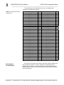
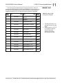
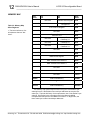
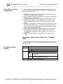
Table 2.1: Board Field I/O Pin
Connections
Non-Isolation
Considerations
Pin Description
LVDS Ch0+
LVDS Ch1+
LVDS Ch2+
LVDS Ch3+
LVDS Ch4+
LVDS Ch5+
LVDS Ch6+
LVDS Ch7+
LVDS Ch8+
LVDS Ch9+
LVDS Ch10+
COMMON
LVDS Ch11+
LVDS Ch12+
LVDS Ch13+
LVDS Ch14+
LVDS Ch15+
LVDS Ch16+
LVDS Ch17+
LVDS Ch18+
LVDS Ch19+
LVDS Ch20+
COMMON
LVDS Ch21+
LVDS Ch22+
LVDS Ch23+
LVDS Ch24+
LVDS Ch25+
LVDS Ch26+
LVDS Ch27+
LVDS Ch28+
LVDS Ch29+
LVDS Ch30+
LVDS Ch31+
Pin
1
2
3
4
5
6
7
8
9
10
11
12
13
14
15
16
17
18
19
20
21
22
23
24
25
26
27
28
29
30
31
32
33
34
Pin Description
LVDS Ch0LVDS Ch1LVDS Ch2LVDS Ch3LVDS Ch4LVDS Ch5LVDS Ch6LVDS Ch7LVDS Ch8LVDS Ch9LVDS Ch10COMMON
LVDS Ch11LVDS Ch12LVDS Ch13LVDS Ch14LVDS Ch15LVDS Ch16LVDS Ch17LVDS Ch18LVDS Ch19LVDS Ch20COMMON
LVDS Ch21LVDS Ch22LVDS Ch23LVDS Ch24LVDS Ch25LVDS Ch26LVDS Ch27LVDS Ch28LVDS Ch29LVDS Ch30LVDS Ch31-
Pin
35
36
37
38
39
40
41
42
43
44
45
46
47
48
49
50
51
52
53
54
55
56
57
58
59
60
61
62
63
64
65
66
67
68
The board is non-isolated, since there is electrical continuity between the
logic and field I/O grounds. As such, the field I/O connections are not
isolated from the system. Care should be taken in designing installations
without isolation to avoid noise pickup and ground loops caused by multiple
ground connections.
__________________________________________________________________________
Acromag, Inc. Tel:248-624-1541 Fax:248-624-9234 Email:[email protected] http://www.acromag.com