1
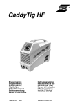
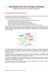
DELOS 2.0.3 User’s manual
august 2006
Fig. 1 – A Geometry and the resulting mesh
1
User’s manual
Aug.2006
1
2
Getting started
This small guide is intended to help you to use Delos software. Delos is
a 2D free mesh generator that deals with partitioned geometries described
by their boundaries. It generates high-quality triangular meshes (that are
suitable for finite element analysis for example) by using the Delaunay’s
criteria.
1.1
Delos input output
The data of Delos are given by files that :
– describe the geometry ;
– define the mesh elements size ;
The output is the file containing the resulting mesh.
Delos can be used in interactive mode or in batch mode. In the first case
the user has to answer the questions while in the second, all the parameters
(the names of the input and output files) has to be given on the same
command line, for example :
delos v
geometry_file
size_file
name_of_mesh
The first and the second arguments are the names of the data files. The
last one is the name of the file which will be generated by the program.
Some parameters are optionals and can be replaced by the character ’-’. In
the next example the user doesn’t give information on the mesh elements
size :
delos v
geometry_file
-
name_of_mesh
The complete syntax of the command can be found in the appendix (the
copy of the help on line).
2
2.1
THE DATA INPUT
The definition of the geometry
The geometry (which have to be meshed) is defined by its boundaries :
a set of borders, each of them containing a list of edges (at least one). Edges
are unique and intersection between them must be their shared vertex. A
geometry made of multiple parts (several materials for example) is described
by borders that may have material on both sides. So a border is defined by
the sorted list of vertex (or nodes) and the two contiguous zones (only one
in the case of the external boundary or in the case of holes). Zones and
vertex are referenced by numbers. The zone number is arbitrary choosen by
the user and -in the resulting file- the triangles filling the zone will have
Aug.2006
User’s manual
3
that number. The vertex number is given by its position in the list of the
coordinates.
For example : vertex 3,11 zones 2,5 means that the edge from vertex
number 3 to vertex number 11 has the zone number 2 on the left side and
the zone number 5 on the right side. See figure 2 for a complete example.
Remark that this method allow the user to define unconnected nodes or
unconnected edges inside a zone. See the next chapter for the full syntax of
the geometry file.
2.2
Mesh size information
Delos allows the user to specify locally the value of the size of the elements. The size of a triangle is defined
as the radius of its circonscribed circle
√
multiplied by a factor equal to 3 . In the case of an equilateral triangle
this is exactly the length of its edges.
The user has 3 ways to define the mesh density :
– He can define cocentrations that are density functions in the plane ;
– He can give the size of the elements on each vertex of the initial geometry.
– If no information is given, then Delos graded the mesh to waranty
well shaped elements. Warning, this method can ONLY be used if
each vertex has only 2 edges (single material).
Each of these ways has advantages and drawback but the definition of
spatial concentration has to be explained.
The size of the elements is given by several functions in the plane S i : so
the size at a point is the minus size of all the concentrations : SAP (x, y) =
M IN (Si (x, y)).
There can be 4 type of density functions :
Uniform : Si (x, y) = constant.
Concentration at a point : Si (x, y) = fi (distance(x, y, point))
Concentration on an axis : Si (x, y) = fi (distance(x, y, axis))
Concentration on an edge : Si (x, y) = fi (distance(x, y, edge))
The functions are geometric (or arithmetic) progressions of given ratio
(or common difference). For example a point concentration will be defined
by the coordinates of the point, a value that gives the wanted size of the
element at that point and the ratio as we are getting far.
So the size of elements is given by :
Progression type : the type of the progression.
Ratio : the ratio (or common difference) of the progression (must be ≥
1.).
Size : The size at the concentration location (must be > 0.).
Location type : the type of the location (point, axis, edge).
User’s manual
Aug.2006
18
9
4
8
7
19
16 15 14
13
17
10 11 12
6
20
1
3
2
5
4
reference number of the boundaries’ vertex
.
2
5
2 5
2
2
5
5
5
2
5
5
2
2
2
5
2 5
2
2
2
5
5
5
reference numbers of the regions
Fig. 2 – Geometry definition
The geometry can be defined by the six border lines which are :
– from vertex 3 to 9, bordering the zone number 5 ;
– from vertex 11 to 15, bordering the zone number 2 ;
– from vertex 11 to 15, bordering the zone number 2 ;
– the vertex list : 9,18,19,20,1,2,3, bordering the zone 2 ;
– the vertex list : 15,16,17,10,11, bordering the zone 2 ;
– from vertex 6 to 7 with zones 5 and 2 on its two sides ;
– from vertex 3 to 11 with zones 5 and 2 on its two sides.
A generated triangle will have the reference 5 or the reference 2 depending
on its location.
User’s manual
Aug.2006
5
Coordinates : of the location, one or two points depending on the type
of the location. Note that the coordinates can be anywhere : in, out
or on the boundary of the geometry.
An uniform mesh can be easily obtened by setting a punctual geometric
concentration with a ratio of 1. See next chapter for the full syntax of the
data file.
(a) Uniform mesh (b) Point concentration
.
(a) Axis concentration (b) Edge concentration
Fig. 3 – Mesh size definition
Notice that the concentrations don’t have to be on a vertex or on an edge
of the geometry.
3
THE OUTPUT
The resulting file contains the triangulation. Each triangle is defined by
its three sides and the zone it belongs to. Thus a triangle is given by four
numbers.
Example : triangle 3, 11, 12 zone 5 means that the border of the triangle
is defined by the three vertex in that order (the dot product of two successive
edges is positive) and that the triangle is in the zone number 5.
The full format of the resulting files is given in the next chapter. But
Delos also gives some messages.
Aug.2006
3.1
User’s manual
6
Information messages
By default Delos gives some information during execution. If you don’t
want any message you must give the silent option : “s”. In the verbose mode
(”v” option) which is the default one Delos write messages on the screen
(standard output). Delos first gives the name of the file and the number
of data it is reading, therefore the zone it is processing and the number of
triangles generated. Delos finally gives the total number of nodes, elements
and zones. A complete message example is following :
>delos v geom density mesh
delos 2.04
DATE 13 9 2006
[email protected]
-->READING SIZE FILE :density
Number of concentrations : 1
-->READING GEOMETRY FILE :geom
Number of points : 4
Number of edges
: 4
Number of zones
: 1
-->WRITTING MESH FILE :mesh
Number of nodes
: 1044
Number of triangles : 1956
Number of zones
: 1
3.2
Error messages :
An error message generally appears if :
– a non-optional parameter is forgotten.
– an input file can’t be opened or its format is not valid.
– a forbidden combination of optional parameters is given.
But an uncorrect geometry (unclosed, self intersecting boundaries...) generates error too and the message -if given- is not necessary obvious. Other
errors may rely on the lack of memory or accuracy.
4
FILE FORMATS
All the file formats follow simple rules :
Blocks : all the files are made of blocks which are delimited by a keyword
of 6 characters DEBxxx at the beginning and FINxxx at the end (xxx
gives the type of the block). The first line of each block gives the
number of lines of the block (without comment lines).
Aug.2006
User’s manual
7
Commentary : Lines outside the blocks are not read by the program. In
a block, a star ”*” in the first row indicates that the entire line is a
commentary.
There are 4 types of file, 7 types of blocks and 5 file formats. The 4 types
of files are :
– the geometry definition file (GEOMETRY format) which contains the
Coordinates block and the borders block.
– the elements size definition file may have 2 formats : the DENSITY
format which contains a Points block, a progressions block and a density block, or the VALUE format which contains only a block of nodals
values.
– the resulting mesh file (UNIVERSAL format) that contains a coordinates block and an elements block.
– an optional output file that contain the evaluation of the elements size
value at each node (VALUE format)
4.1
Geometry definition file (format ARETE)
The file containing the geometry definition is composed by 2 blocks :
the points coordinate block (letters XYZ) and the border’s definition block
(letters ARE for ARETE in french) which defines the connexion between
the points. The format is the following :
--------------------------------------------------------------DEBXYZ
= beginning of the points coordinates definition
nbc dim
nbc = number of points
dim = dimension of the space
x1 y1
...
xn yn
FINXYZ
= end of the points coordinate’s definition
DEBARE
= beginning of edges defintion
nbl
nbl = number of lines
* this is a comment line inside a block
* a border can be defined by a list of points :
nbs1 no1 no2 ... nos 100 nbr1 reg1 reg2 ... regn1
nbs1 = number of points on the border
...
no1... nos = reference’s number of the points
100 = code for straight line edges
nbr1 = number of zones (1 or 2)
reg1 reg2... reference numbers of the region(s)
*
* a list of interior points (unconnected points) :
Aug.2006
User’s manual
8
nbsi noi1 noi2 ... nois 99 1 regi1
nbsi = number of interior points
...
no1... nos = reference numbers of points
99 = code for unconnected points
1 = there is only one region
regi1 = reference numbers of the region
*
* sometime a set can also be defined by an interval :
-3 nod nof pas code nbr1 reg1 reg2 ... regn1
-3 = code for an interval’s definition
nod = reference number of the first point
nof = reference number of the last point
...
pas = step from the first to the last point
code = 100 or 99
*
FINARE
= end of the edges definition
---------------------------------------------------------------
4.2
Mesh size definition file (format DENSITE)
The first way to define the size of the elements of a mesh is to give
functions in the plane. The file contains 3 blocks : a coordinates block, a
block that includes the progressions definition (letters SUI for SUITE that
means progression in french) and the densities block that refers to the first
two blocks. The format is the following :
--------------------------------------------------------------DEBGEO
= beginning of the points coordinates definition
n 2
n = number of points
2 = dimension of the space
1 x1 y1
...
i xi yi
i = the number of the point
xi = abcisse of the point i
...
yi = ordonate of the point i
n xn yn
FINGEO
= end of the points coordinates definition
DEBSUI
n
1 ty1
2 ty2
...
i tyi
= beginning of the progressions definition
= number of progressions
vi1 r1
vi2 r2
vii ri
Aug.2006
User’s manual
9
tyi = type of the progression i,
(1 = geometric, 2 = arithmetic)
vii = initial value of the prog. (float >0.)
ri = ratio
"
"
" (float >1.)
...
n tyn vin rn
FINSUI
= end of the progressions definition block
DEBDEN
n 1
= beginning of the densities definition
n = number of densities
1 = generation mode (obslotet)
1 ty1 m1 ref11 ... ref1m
...
i tyi mi refi1 ... refim
tyi = type or location of the concentration i
1 = concentration at a point
2 = concentration on an axis
3 = concentration on an edge
mi = number of reference for the concentration
2 = for points concentration
3 = for axis or edges concentration
refi1 = reference number of the progression(see
DEBSUI block)
refi2 ... refim = reference number of the point that
defines the location (see DEBGEO block)
* for example :
i 1 2 refi1 refi2
= concentration at a point
refi1 progression at the point refi2
j 2 3 refj1 refj2 refj3 = concentration on an axis
refj1 progression on the straight line
...
defined by the points refj2, refj3
n tyn mn refn1 ... refnm
FINDEN
= end of the densities definition block
---------------------------------------------------------------
4.3
Mesh size definition at each node (VALUE format)
The second way to define the mesh element’s size is to give the desired
size at each point of the geometry. The file’s format is trivial : it is only
composed by a block of values (each one for a point).
-----------------------------------------------------------DEBGRD
= beginning of the values definition block
n 1
n = number of lines
Aug.2006
User’s manual
10
1 x1
1 =
...
i xi
i = reference of the value
...
xi = flotting point value
n xn
FINGRD
= end of the values block
------------------------------------------------------------
4.4
Resulting mesh file (UNIVERSAL format)
It is composed of 2 blocks : a coordinates block and an elements block
that contains the triangles definition.
-----------------------------------------------------------DEBXYZ
= beginning of coordinates definition
n dim
n = number of points
d = dimension of the space
x1 y1
...
xn yn
FINXYZ
= end of coordinates definition
DEBILM
= beginning of element’s definition
n
n = number of elements
3 n11 n12 n13 3 reg1
...
3 ni1 ni2 ni3 3 regi
3 = number of nodes of the element
ni1,ni2,ni3 = reference number of each node
3 = code for the linear triangle element
...
regi = zones reference number i of the element
3 nn1 nn2 nn3 3 regn
FINILM
= end of elements definition
------------------------------------------------------------
Aug.2006
A
User’s manual
11
APPENDIX : Help on line
delos(1)
DELOS
Nov - 2006
delos(1)
NAME
delos - 2D free mesh generator (triangles).
SYNTAX
delos [v/s] namef1 [namef2] [namef3] [namef4] [nbnmax]
DESCRIPTION
delos is a 2D mesh generator that produces triangles. It
can be used in interactive of batch mode.
[v/s]
:
execution mode with message (v=verbose option) or without
(s=silent option). It is useless in interactive mode.
namef1 : name of the file which defines the geometry.
namef2 : name of the input file which defines the mesh density. It
may be optional for a single zone geometry.
namef3 : name of the resulting file which will contain
ted mesh.
the genera-
namef4 : (optional) name of the resulting file which will contain
the desired element size at each node of the mesh.
nbnmax : (optional)set the maximum number of nodes in the resulting
mesh. It may be given if the geometry is a single region
otherwise the result may be unexpected.
0 : no interior node is generated
-1 : no limit is fixed
>0 : at most the resulting mesh has nbnmax nodes. Then the
density may not be satisfied.
EXEMPLES
delos v geom dens mesh
generates a file named
"mesh" which
contain a mesh of the
Aug.2006
User’s manual
geometry defined in the file
defined in the file "dens".
12
"geom"
with the
density
delos v geom dens mesh - 0
generates the triangulation
interior node.
of the
geometry
without
any
delos v geom - mesh
generates as
triangles.
many
nodes
as needed to obtain well shaped
delos v geom dens - denson 0
the file "dens" contains the density definition and the file
"denson" the size value of the desired triangle size at each
node of the resulting mesh.
AUTHOR
delos has been developed at the School of Mines by O.Stab.
VERSION
version delos - 2.0.3 (Jan. 2005)
E.N.S.M.P
-1-
Nov
06