1
Bilt User Manual
Bilt User Manual, P1/62
Bilt User Manual
Mainframes BN100, BN101, BN103 and BN105
Bilt User Manual
Bilt User Manual, P2/62
Contents
I Important information (Must be read)...............................................................................................3
1. Safety information..................................................................................................................3
2. EC Declaration of Conformity.....................................................................................................5
3. Technical characteristics..........................................................................................................6
II Bilt Presentation........................................................................................................................7
1. Bilt unit overview...................................................................................................................7
2. Power management of the Bilt units.............................................................................................9
3. Bilt unit connections and panels features.....................................................................................13
4. Modules.............................................................................................................................14
III Hardware installation................................................................................................................17
1. Main frame installation...........................................................................................................17
2. Modules installation...............................................................................................................18
3. Communication interfaces : connection to a computer.....................................................................19
IV Bilt Programming.....................................................................................................................20
1. General presentation.............................................................................................................20
2. BILT operating principle..........................................................................................................21
3. BILT SCPI commands..............................................................................................................22
4. SCPI program samples............................................................................................................36
V Front panel display usage (BE740 option).........................................................................................38
VI Software tools........................................................................................................................39
1. Overview............................................................................................................................39
2. Installation.........................................................................................................................40
3. Setting up communication.......................................................................................................40
4. Using Bilt with BiltTerminal......................................................................................................41
5. Using Bilt with BiltLab............................................................................................................44
6. Updating Bilt's CPU board firmware with TeleBilt............................................................................54
VII Calibration............................................................................................................................59
VIII Maintenance.........................................................................................................................60
IX Warranty and customer support...................................................................................................61
Itest reserves the right to modify the content of this document without prior notice. Itest may improve or
upgrade any product presented in this manual. Itest may not be held responsible for any error or omission. All
equipments and options described may vary according to customer requirements.
Copyright © 2011 Itest S.A.R.L.
All Rights Reserved. Bilt trademark and logo are registered trademarks of iTest SARL.
All other trademarks are the property of their respective owners.
Bilt User Manual
Bilt User Manual, P3/62
I
Important information (Must be read)
1. Safety information
Make sure to read the entire manual before using Bilt system!
•
Bilt system is designed for use solely in industrial and laboratory environment by skilled staff. It is your
responsibility to use the product in an appropriate manner. When using Bilt, make sure to comply with the
following safety guidelines in order to avoid the risk of : fire, electric shock, injuries or equipment damages.
Itest disclaims any responsibility or liability for any harm or damage resulting from the misuse of Bilt, its
modules and its derivative products according to all safety information, precautions and installation
procedure listed in all this document and in module's datasheets. Any lack of compliance may damage the
system. The manufacturer's guarantee will be null and void if any of these clauses has not been respected.
Please read the entire document before using Bilt.
Symbols :
Danger, read documentation
•
•
•
Danger of electric shock
Earth
Bilt must be earthed and powered by a 110V 60Hz or a 220V 50Hz network, depending on the mains input
board of the Bilt Sytem. The lack of earth connection can lead to injuries or death in case of electric shock.
Some high voltage modules involve a risk of potential death. These modules can be identified by the “electric
shock” sign above, which is marked on their front panel. The operator must take all necessary safety
measures and make sure that no conductive part is exposed.
Modules may only be installed or removed when the mainframe is switched off. If this clause is not respected
the module, the mainframe and all other modules may be damaged. We recommend that you always screw
down the modules correctly in order to avoid accidental live ejection of the modules particularly during
disconnection of the 4mm jacks.
3
2
888
power
1
Bilt User Manual
Bilt User Manual, P4/62
•
•
•
•
•
•
•
•
•
•
•
•
•
•
•
•
For measurements/supply of circuits with voltages Vrms>30V or Vdc>70V, suitable measures should be taken
to avoid any hazards.
Modules which do not have over-voltage protection system or whose system have been deactivated may be
damaged if they receive a permanent voltage greater then the active range or greater than a few hundreds
of mV in reverse.
No internal maintenance operation may be performed by the operator without iTest agreement, particularly
because of dangerous internal voltage even when Bilt is switched off. Dismantling of the upper or lower lids
of the mainframe is forbidden and will void the warranty.
Do not insert hand in the rear of the mainframe if modular positions are empty whether Bilt is switched on or
off (risk of electric shock). Fill all module's empty slot with a stainless-steel panel screwed on the mainframe
as a module (contact us to order such a panel).
Make sure that ventilation openings are clear and that the room is adequately ventilated.
In case of internal capacitor failure, a small amount of toxic gas can be released. Take all necessary measures
to ventilate the room and contact iTest's after-sales service.
The product has no power switch for disconnection from the AC supply, the plug of the connecting cable is
regarded as the disconnection device. It must be ensured that the power cable is easily reachable and
accessible at all times. If Bilt is integrated in racks or systems, a disconnecting device must be provided at
the system level.
The product may be operated only from TT supply network fused with max. 16A.
Never use the Bilt system under conditions in which condensation has formed or can form in or on the
product; e.g. if the system was moved from a cold to a warm environment.
Do not place Bilt near heat-generating devices.
Don't use any device or equipment near a liquid.
Do not stack anything on the mains cable.
Do not insert any object or liquid in the mainframe's openings to avoid electric shock.
Try not to use Bilt during a storm or use surge arrester devices.
Prior to cleaning, disconnect Bilt from the AC supply. Use a soft, non-linting cloth to clean the product. Never
use chemical cleaning agents.
Unplug immediately the mains cable if the mainframe has fallen or has been damaged.
Bilt User Manual
Bilt User Manual, P5/62
2. EC Declaration of Conformity
according to ISO/IEC 17050-1:2004, DoC #02-2009
Manufacturer's name : iTest S.A.R.L.
Manufacturer's Address : 119, rue de la Providence
31500 Toulouse - France
declares under its sole responsibility that :
Product name : Bilt / Tiny Bilt
Product Configuration : ALL1)
Product Options : BE715, BE717
Accessories : ALL2)
conforms to the following Product Specifications:
Safety : CEI 61010-1:2001 2nd edition: Safety requirements for electrical equipment for measurement, control, and
laboratory use
EMC : CEI 61326-1 (July 1997 +A1 1998 +A2 2001 +A3 2004): electrical equipment for measurement, control, and
laboratory use – EMC requirement – Part 1: general requirements
EN61000-4-2: Electrostatic discharge (ESD)
EN61000-4-3: Radio-frequency electromagnetic field
EN61000-4-4: Electrical fast transients/burst immunity
EN61000-4-5: Surge immunity
EN61000-4-6: Conducted high frequency disturbances
EN61000-4-8: Power-frequency magnetic fields
EN61000-4-11: Voltage variations, dips and interruptions
EN55022 Class A: conducted and radiated emissions
CEI 61000-3-2: mains harmonics (only for mains input board ref. BN603)
Supplementary Information :
•
The products herewith comply with the requirements of the Low Voltage directive 2006/95/EC, the EMC
directive 2004/108/EC and carry the CE
marking accordingly.
•
This Device complies with Part 15 of the FCC Rules. Operation is subject to the following two Conditions: (1)
this device may not cause harmful interference, and (2) this device must accept any interference received,
including interference that may cause undesired operation.
•
This declaration is valid as far as the product is used according to the user manual.
•
In a residential environment, the equipment may cause radio frequency interference. In this case the user
may be required to take appropriate measures.
1) The product was tested in two typical configurations. List of tested parts: BN101, BN721, BN606, BN603, BN602,
BN613, BN614, BE718, BE584, BE841, BE842, BE515, BE516, BE517, BE427, BE437, BE534, BE549, BE715.
The modules or sub-assemblies not tested are of the same design rules as the ones above. They accordingly give the
product the conformity to the same standards. List of concerned elements at the date of issue of the DoC: module's
family BE52X, BE53X and BN61X, BE580, BE582, BE585, BE586, BE587, BE561, BE426, BE547, BE548, BE572, BE832,
BE810, BE470, BE471, BE474, BE481, BE482, BE483, BE433, BE435, BE436, BE592, BN609, BN105, BN723, BN722,
BN607, BE717.
2) The accessories are cables, printed boards, heating or cooling systems.
Place of issue: 119, rue de la Providence 31500 Toulouse - France
Date of issue: July, 10th 2009
Hervé CONSTANS
General manager
For regulatory compliance information contact :
Worldwide Contact : iTest, 119 rue de la Providence, 31500 Toulouse, France, +33 (0)561548130
Bilt User Manual
Bilt User Manual, P6/62
3. Technical characteristics
Mains input
Topology
Active PFC (BN603)
Rectifier (BN602)
100-240Vac
220-240Vac
600W-1200W
900W
6A
4A
47-63Hz
47-63Hz
Single
Single
13A max.
4A max.
> 80% @ 230Vac
98%
Power factor
0,99 typ @ 110Vac
0,97 typ @ 230Vac
-
Start-up time*
< 3s
< 3s
Hold-up time*
700ms (no load) – 100ms
(500W)
700ms (no load) –
100ms (500W)
Leakage current*
6mA max.
3mA max.
Internal Protection
overload, over-heating, overvoltage, short-circuit
-
Voltage range
Input Power
Current
Frequency range
Phase
Inrush current
Efficiency
Connectors
Mains input unit
Standard IEC receptacle
∅4mm Socket (earth)
MicroFit® (“Safety Stop”)
Bilt's front panel
SUBD-9 female (RS232)
USB Type B female
PS/2 (keyboard, if front display option)
CPU unit
SUBD-9 male (RS422)
USB Type B female
RJ45 (Ethernet)
IEEE-488 female (GPIB)
BNC female (trigger)
Miscellaneous
Dimension
Operating temperature
Storage temperature
Humidity
Installation category
Environment
19'' 4U mainframe
482x178x405mm
5°C à 40°C ambient
Power derating over 25°C
0°C to 70°C
0 to 80% RH, non condensing
CAT II
Indoor use, pollution degree 2
* Depends on the number/model of primary power converters used. Characterized here with 2 BE613 (300W).
Bilt User Manual
Bilt User Manual, P7/62
II
Bilt Presentation
1. Bilt unit overview
Bilt is a modular system designed to both generate and monitor high
quality signals for test benches and laboratory applications.
The standard modules are high performances DC sources supply.
A range of extra modules includes functions as varied as temperature
controller, pulses and pattern generation, multi channel measurement,
relay driver and, last but no least, specific application modules.
The Bilt mainframe supplies hardware and software requirements for
any set and combination of modules: powering, air cooling,
synchronizing, dedicated data setting and logging.
The system is well suited for systems requiring both remote controller and network connection for overall control.
A large choice of connections is available whatever the mainframe type: RS232, RS422, GPIB, USB and Ethernet.
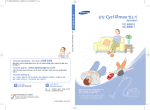
1.1. Mainframe items description
The Bilt mainframe is available according to 4 different sizes and formats:
Front view:
Ref
BN100
BN101
BN103
BN105
nickname
standard
“with display”
micro-Bilt
Tiny-Bilt
Slot Number
13
13
5
8
module position
back
back
front
front
Display
--
B&W LCD 120x70mm
--
B&W LCD 120x70mm
maximum output power
Configurable, up to 780W+
Configurable, up to 780W+
260W+
210W+
rack size ( W, H, D)
19'' x 4U x 360mm
19'' x 4U x 360mm
half 19'' x 4U x 260mm
19'' x 4U x 260mm
fixing and handling
rack brackets +handles
rack brackets +handles
handles(bracket in option)
rack brackets +handles
Rear view:
note:
• The standard Bilt unit has 13 slots for the modules located at the rear, well suited for a cabling integrated in a rack.
The smallest versions have the modules located at the front, well suited for desktop or standalone use.
• The optional LCD display is useful for measurement and setting read-back or for easing development steps.
• The Bilt mainframes are fitted with different primary power supplies according to the user application requirements
and the mains specification.
• The front panel is fitted both for rack stacking and fixing or for handling as a standalone equipment.
• In any case, the cooling air flow needs both front and rear clearance, but complies with stacking.
Bilt User Manual
Bilt User Manual, P8/62
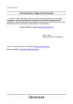
1.2. Radiography of a Bilt unit
a standard Bilt unit is made of:
3
1
1
A mother board
2
A mains input board for AC/DC conversion.
3
one to four primary power converters
4
A main controller board
5
location for up to 13 modules
4
5
2
1
3
Mains Input
Unit
2
Modules
Chassis
mother
board
5
Primary
Power
Module
CPU
4
Bilt Bus
Bilt User Manual
Bilt User Manual, P9/62
2. Power management of the Bilt units
2.1. Power conversion principle
The power conversion from the mains voltage to the DC source output is always proceeded through two steps:
•
First, the AC input voltage is converted into a common rail DC low voltage using a set of internal power
boards. The common rail along the backplane is made of two different voltages, +25V and -25V, whose
maximum available current/power is to be set according to the application.
•
Then, each DC source module sinks power from the common rail to supply its output regulator providing high
performances signal for the application. In addition, the common rail is used to supply all the internal
circuitry of the system, thus adding an offset on the required power.
The Bilt system can be either 110-220V AC voltage compliant using PFC input stage, or only 220V AC voltage compliant
using simple rectifier, which is more efficient for large power.
As the Bilt mainframe comes with a large choice of size and power equipment, the challenge for the user is to
forecast how much power will need the application:
•
The simplest but wrong way to proceed is to add all the maximum power values that each plugged module is
able to deliver according to its own specification. This will lead to waste expensive power boards and,
anyway, the Bilt main-frames are not designed to withstand the sum of all its modules crest power: 120W is
the standard maximum output power for one module, but the maximum average output power for 13
modules within a standard Bilt unit is only half, ie 60W x 13 = 780W.
•
The advisable way to proceed is to add the maximum power values that each load is going to sink, then to
ensure that the available primary power is larger. For this purpose, the specification of the primary power is
always given in term of “equivalent output power”, including the common efficiency of the Bilt modules
themselves. Most of the output modules suck significant power only from the +25V common rail. The -25V
common rail is used to supplying both low power applications and internal circuitry.
As power consumption forecasting is difficult, the measurement of the actual primary power consumption is included
in the Bilt monitoring parameters, for both common rails +25V and -25V. Therefore, at any time, the user can display
the maximum available power value and the ratio between the used power and the available power. Furthermore, if
the ratio rises well above the maximum 100% value, the Bilt unit will disable all the outputs while proceeding a proper
backup and sending a warning message.
When using tough loads, as switching, capacitive, reactive, high voltage, the user should be aware that transient
current can occurs back to the common rail, and therefore a larger power margin can be required.
Bilt User Manual
Bilt User Manual, P10/62
2.2. Power supply setups
The smallest versions of BILT mainframes BN103 & BN105 are fitted with a fixed and embedded primary power supply.
The standard BILT mainframes BN100 & BN101 are powered by a configurable primary power system, ranging from a
minimum of 130W up to a maximum of 780W. For general purpose application, they are proposed with a choice of
standard power packages defined in the following table.
Mains specification
Mainframe
option description
BE103 Micro-Bilt
BE105 Tiny-Bilt
BE100 / BE101
standard
mainframe
AC voltage
range
maximum
input power
110V - 220V
480W
equivalent output power
issued from:
power board package
-25V
common rail
+25V
common rail
embedded / fixed power
80W
260W
220V
450W
BN602 / fixed power
130W
210W
PFC
110V - 220V
500W
BN603 / fixed power
130W
210W
light power
220V
260W
BN081 = BN602+BN614+BN611
65W
130W
standard power
220V
450W
BN082 = BN602+BN614+BN613
65W
260W
medium power
220V
800W
BN083 = BN602+BN614+2*BN613
65W
520W
maximum power
220V
1100W
BN084 = BN602+BN614+3*BN613
65W
780W
light power & PFC
110V - 220V
275W
BN071 = BN603+BN614+BN611
65W
130W
standard power & PFC
110V - 220V
475W
BN072 = BN603+BN614+BN613
65W
260W
For special purpose application, the BILT mainframes BN100 & BN101 can be delivered with any set of primary power
converters. This can be done either before delivery or later on, just by plugging or unplugging power DC/DC
converters, within the 4 internal slots hidden behind the front panel of the unit.
ref
specification of the primary power converters
equivalent output power
polarity, ie supply
+25V or -25V common rail
BN611
DC/DC 400V to 25V 6A
130W
either, set by straps
BN613
DC/DC 400V to 25V 12A
260W
either, set by straps
BN614
DC/DC 400V to 25V 3A
65W
only for negative -25V rail
BN612
DC/DC 400V to both +25V 3A & -25V 3A
2 x 65W
both common rail, +25V & -25V
The system requires both positive and negative primary power, at least for internal circuitry supplying.
The table here-above specifies how the primary converter can supply the positive rail, or the negative, or both.
When several primary converters are plugged and set to supply the same common rail, they work well in parallel and
when the system is not operating at full power it distributes the consumed power between them.
The monitoring of the actual primary power consumption for both common rails +25V and -25V will indicate the total
value of available power and the total value of ratio between the used power and the available power.
See EasyStress software user manual or SCPI commands section for access to primary power monitoring.
Caution: The modification of the available power within a Bilt mainframe needs to unscrew the front panel and
therefore to access to the high voltage area. The mains should have been previously disconnected. A dedicated
maintenance sheet is available, allowing to proceed safely to this modification.
Bilt User Manual
Bilt User Manual, P11/62
2.3. Power management facts
2.3.1. input power switch
The input power is switched ON and OFF by a power transistors and a control circuitry which performs:
➢
soft start with limited inrush current.
➢
ON/OFF command on both front panel and rear panel using a remote single push button.
➢
memory of the state after mains interruption: if previously ON, the unit will restart without press the button.
➢
safety breaker function: the unit is switched off in case of any fault condition. It will stay OFF until the
operator try to push again the ON/OFF button. The default can be either:
•
a drop down of one of the 25V common rail voltage
•
an internal thermal alarm or an overrun of the maximum input power (only BN603 PFC )
2.3.2. AC/DC input converter
The BE103 Micro-Bilt mainframe is fitted with an PFC input converter which sustains its maximum power whatever the
mains voltage within the 110V to 220V range.
The standard mainframe BE100/BE101 performs its maximum power level when connected to 220V AC voltage.
The maximum power is limited to half when connected to 110V AC mains, using the BE603 – PFC board.
Mains input board
AC voltage range
maximum input power
total equivalent output power
BE103 Micro-Bilt
Mainframe
integrated PFC
110V - 220V
480W
340W
BE100 / BE101
standard
mainframe
BN 602
220V
1,1KW
850W
BN603 - PFC
220V
1,2KW
850W
110V
600W
450W
2.3.3. common output ground
The mainframe’s electrical ground is referenced to the mains ground.
- In DC to within 1V by means of adjoining power diodes in opposite directions. This
maximum offset is sufficient to ensure that the power return current does indeed return to
each rack through the (GND) cables and not via the mains ground.
- In AC by means of several ceramic capacitors distributed on each Bilt modular board as
well as in the rack (on the motherboard). This makes it possible to ensure quality and
referencing of filtering and also EMC protection for the whole system.
Warning : using Bilt thanks to RS232 interface and a PC makes that Bilt's ground and earth
are shorted.. Use the insulated RS422 interface if necessary (BE717 option : external case
interfacing USB to RS422).
Bilt User Manual
Bilt User Manual, P12/62
2.3.4. temporary power backup when the mains stops
System reaction to mains cutoff
Bilt has an integrated "emergency mains cutoff system" which guarantees to the control system a sufficient
power autonomy to ensure a clean break. Hence the DC sources continue to control the set values until the short
circuit relay is shut off which guaranties that there are no transients on the output. In addition, when the rack is used
with EasyStress for stress tests, the date and time of the mains cut-off are recorded in each group's trace memory.
•
Warning : The autonomy only concerns control and low power signals. If, for example, you are using a BE510 with a
range of a few mA to send commands to a MOS gate and if you have programmed a stopping time of 50ms in relation
to the module providing the drain voltage, the sequencing will be respected. but if you want to set a stop time for a
signal of several watts, the signal will collapse before execution of the stop time due to lack of primary power. What
the system guarantees even in this case is the lack of transients or undesirable random effects on the output.
Communication with BE718 anticipates mains input disappearance by stopping Bilt's module before lack of power.
Bilt User Manual
Bilt User Manual, P13/62
3. Bilt unit connections and panels features
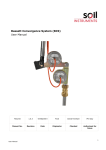
3.1. CPU board
Processor : STR912FA, core ARM 966-E at 96MHz, 512ko Flash,
96Ko SRAM + 2Mo SRAM (external memory, backed-up thanks to a
battery), internal clock and calendar.
Memory : 2Mo external Flash
Clock : 100MHz oscillator for mainframe clock generation and GPIB
clock.
Battery : Ni/Mh 3,6V at least 3 months retaining capability without
powering Bilt.
Interfaces :
•
RS232, EIA/TIA-232E and CCITT V28 compliant (±10V)
•
RS422 56k/207k, insulated (±5V)
•
GPIB (IEEE488.2), National Instrument TNT4882 at 40MHz
•
Ethernet 10/100M on insulated RJ45 (LVDS)
•
USB 2.0 slave (5V)
•
Trigger : open collector (5V)
BE718 CPU board (on the left)
3.2. Front panel
A « SAFETY STOP » connector on the front panel of the mains input board is part of a safety system which
stops the DC source modules if the electrical loop between two of its contacts is opened (example : for a door contact
when using high voltage modules).
Bilt User Manual
Bilt User Manual, P14/62
4. Modules
4.1. Generalities
Module identification
Each Bilt module has an E²PROM memory containing its complete identification. On initialization, the system
reads the identification of each module from this memory and loads the relevant software structure. Thus, the
selection of a module slot activates the set of SCPI commands related to the instrument installed.
For instance, if slot 4 has a BE427 temperature module the command «meas :temp ? » will return the
temperature measurement. The same command to the same slot with a DC BE516 source installed will return the SCPI
error message « undefined header ».
An SCPI command can be used to identify the type of module installed in the slot in question as well as its
serial number, its software version and the date on which it was last checked or calibrated.
•
Permanent memory
The system memory and clock are saved by battery power.
CPU
Horloge
Thus if you have programmed a module’s parameters and you switch
Mémoire
Batterie
BE718
off and then switch on the system without changing the module's
programme
place in the rack, the parameters will remain unchanged. This system
(flash)
feature was designed for stress test requirements using EasyStress
software but can have undesirable effects when directly used in SCPI
MicroMémoire
mode. In particular if a rack has been used in the EasyStress
processeur
données
environment then the command « *rst↵ » should be used to reset the
rack before using it in SCPI mode. Indeed EasyStress activates
operation of modules in groups with group level alarms which can prevent the module from operating correctly with
its own commands.
•
Software changes
The CPU board's firmware is memorized in a flash memory. This firmware may evolve to improve Bilt's
performances. A PC software (« TeleBilt ») is provided to update the firmware of the rack very easily. The latest CPU
software file can be obtained on a CD ROM, E-mail or by direct download on iTest website (www.itest.fr). It should be
noted that the firmware update can be done simultaneously for several networked racks.
The module's firmwares should not change. But, in particular cases and under iTest advice, they also can be
updated thanks to another PC software (« TeleModule »). In such a case, TeleModule software and the firmware file
will be provided on a CD-ROM.
•
→ Full list of modules and accessories on www.itest.fr
Bilt User Manual
Bilt User Manual, P15/62
4.2. DC sources
Bilt DC sources are characterized by very accurate setting and
measurement. These performances are achieved thanks to a wide choice of
ranges (e.g.: 9 current ranges for the BE516, from 5µA to 6A full scale). It is
important to correctly choose the range to be used. By default, modules come
in automatic range selection mode, i.e. when stopped they automatically select
the suitable range according to the past setting (current or voltage). You may
change the setting in operation but only within the same range. Remember
there will be a loss of accuracy if the setting (or measurement) becomes too
small in relation to the actual resolution.
Most of these power supplies are not floating but referenced to a
common ground : it is impossible to connect them backwards to obtain negative tension, or to cascade them to double
the voltage. On the other hand most of them are bipolar and may be programmed in negative.
DC sources for the Bilt system are referenced to the
common electrical ground of the rack.
This enables to :
- Substantially reduce the cost.
- Enable simple and efficient filtering without capacitors on
output (no problem of common mode noise).
- Avoid electrostatic discharge due to isolated systems.
- Clearly references ground layouts.
Module 2 out
Volt -12
Module 1 out
e
Volt 12
To deliver a negative signal, the sources are bipolar
and power outlets are marked “GND” “OUT” (and not “-“ and
“+” as for a floating power output).
Since the ground for each source is also common at the test
equipment level the system uses 4 wire remote sensing which enables:
An identical cross section for all power (OUT) and return (GND) leads.
A stable and accurate voltage regulation while compensating losses on
individual lines (OUT SENSE) and especially common lines (GND SENSE).
e
-12V
gnd
+12V
gnd
Module
out
out sense
e
gnd
Gnd sense
sense
In order to protect the linked components under all circumstances (in particular during mains powering up or
powering down of the mainframe), most of Bilt DC source modules have short circuit relays : when these are off they
have null impedance in output.
Bilt User Manual
Bilt User Manual, P16/62
Most of Bilt DC sources features an Over-Voltage Protection system. See each module's datasheet to see the
availability of this fonction.
Unlike what may be available on other SCPI power supplies, the over-voltage-protection of Bilt modules is a
stand-alone hardware system whose response time is short enough to efficiently protect the module against an
accidental short-circuit with a voltage greater than its acceptable range (or even much greater) or a reverse voltage
(>500mV in the opposite direction to the current range). Let us take the example of the polarization of a power MOS
at 250V on the Drain with a BE537 and at 15 Volts on the gate with a BE516 on a very low current range for monitoring
the leak. Following a failure of the MOS or a handling error, the 250V voltage is applied on the output of the BE516
module. This one will protect itself in three stages :
1. A power transil will limit the voltage to about 120% of the maximum voltage range of the DC source (within a few
pico-seconds).
2. Detection of over-voltage (if the pulse is longer than 1µs), triggering of a power short-circuit system (within 10µs).
3. Normal stopping of power supply (software) setting at 0V and 0A then activation of the short-circuit relay (stage
duration: 60ms).
Note that this very efficient system is operational even for low current ranges, without deterioration of performance
in terms of accuracy and leakage current.
Important note : in the case of a group stop through over-voltage protection this stops with respect to the
programmed inter module sequences except for the module which triggered the alarm. As indicated above in order to
protect against over-voltage the module short-circuits its output with a very short response time.
→ Full list of modules and accessories on www.itest.fr
Bilt User Manual
Bilt User Manual, P17/62
III
Hardware installation
1. Main frame installation
Each Bilt mainframe is delivered in an individual parcell containing also a mains cable. All ordered modules
are already installed in the mainframe and screwed down. Bilt is thus immediately fully operational without any
installation procedure. Simply connect the supplied mains cable between the mainframe and an earthed plug and
choose a communication interface to start using Bilt. The mains voltage must match the Bilt system installed mains
input board voltage range (BN602 or BN603).
Make sure that ventilation openings are clear and that the room is adequately ventilated.
Starting/stopping Bilt :
Press the push-button « POWER » on the front panel of the mains input
board or on the mainframe's front panel. The start-up time may vary from 1 to 4
seconds depending on the number of primary converters installed.
In case of mains cut-off, Bilt will restart as soon as the mains returns.
The « SAFETY STOP » connector on the front panel of the mains input
board is part of a safety system which stops the DC source modules if the
electrical loop between two of its contacts is opened. This enables, for instance
connecting this loop to the access door of a room, to stop high voltage modules in
case of intrusion.
Using the front panel programmable keys :
Two keys marked « F1 » and « F2 » can be freely programmed thanks to SCPI
commands. They can simply switch the modules on or do much complex
functions.
Control LEDs :
« Listen » LED : incoming communication in progress
« Talk » LED : outgoing communication in progress
« Error » LED : communication error
« Alarm » LED : at least one module sent an alarm
« Output » LED : at least one module is on
Bilt User Manual
Bilt User Manual, P18/62
2. Modules installation
All Bilt are delivered fully assembled. However, you may need to change your configuration by removing or
replacing modules.
These operations must imperatively be done when Bilt is switched off.
Otherwise, modules may be damaged.
To remove a module, after unscrewing it, pull its handle retaining the module with your other hand on top of
its front panel. Once the module has disengaged from the mainframe connector, pull it gently away from the chassis
maintaining a proper alignment between the brackets and the module.
Insert without forcing the new module into its slot, ensuring proper alignment between the brackets and the
module so as not to tear the module components out because of the neighbouring module. Pressure is needed at the
end of the race to set the module connector in the mainframe connector. After full integration of a module in its slot,
screw it down to the mainframe at least at one of the two locations.
Unused modules must be stored in an electrostatic bag.
Connection to the modules
Read each module's documentation to get input or output connector information.
The supplying of loads over long distances (>3m) needs possibly additional RF rejection hardware to get in conformity
to the EMC requirements.
Using modules :
All modules are automatically detected and identified at Bilt's start-up. No driver installation is necessary if CPU's
firmware is up to date. Modules are then ready to be controlled by SCPI commands.
Bilt User Manual
Bilt User Manual, P19/62
3. Communication interfaces : connection to a
computer
The standard version of the system comes with five interfaces : RS232, RS422, GPIB, TCPIP and USB.
The RS232 and USB interfaces, which are accessible on the front panel, enables
very easy control of one rack through a computer’s serial interface (COM or USB
on a PC for instance). It is generally used for maintenance operations or for local
operation using a terminal emulator such as the Windows Hyper Terminal.
(Serial configuration : 8 data bits, no parity bit, 1 stop bit, no flow control)
RS422
Interface
BILT
BILT
BILT
COM1/2
or USB
RS232
or USB
(front panel)
BILT
Several Bilt racks can be connected in a network via the RS422 interface (up to
99).The advantage is that it enables simple, cheap wiring and can handle long
distances.
Note : Optional BE717 accessory, which provides a self-powered isolated
USB/RS422 interface, is available separately.
The GPIB interface is a rapid parallel network with standard electrical and
mechanical specifications. This is the easiest way of integrating Bilt into a
heterogeneous test bench. Bilt is entirely compatible with the IEEE488.2
standard for GPIB operation.
Interface
GPIB
Instrument X
Instrument Y
BILT
gate
TCP/IP Ethernet interface is fully standard (100Mbs, RJ45, full
duplex, port 5025). It may be used on a specific network (just as
RS422 and GPIB) or on a company network.
switch
switch
Instrument Y
BILT
BILT
Default addresses :
RS422 : last two digits of the serial number
GPIB : 05
Ethernet : 192.168.150.1xx, xx are the last two digits of the serial number. Port 5025 is not configurable.
Bilt User Manual
Bilt User Manual, P20/62
IV
Bilt Programming
1. General presentation
1.1. Requirements
For development of programs, a terminal interface is required.
– If Bilt rack is equipped with a display (BE740 option), this display can be used as terminal by plugging a PS2
keyboard on the front panel.
– In all cases, a PC computer can be used thanks to the iTest “BiltTerminal” software provided.
Note : Under Microsoft Windows OS, “HyperTerminal” software can also be used.
1.2. SCPI commands overview
No matter what type of interface is used, the BILT system only accepts and returns ASCII character chains in
an SCPI format.
SCPI stands for “Standard Commands for Programmable Instruments”. The purpose of this norm is to
standardize the instruments commands between programmable test and measurement devices from different
manufacturers.
The syntax is based on the use of the most explicit keywords possible with a long and a short form (e.g. : the
SCPI command VOLTage can be written volt or voltage) possibly preceded by a « root command » (e.g. meas:volt). If
the command has an argument, it is placed after the keyword, separated by a space (volt 12). If the command must
return data, the key word is followed by « ? » (meas:volt ? ↵ → answer : 1.002 ).Whether on input or output, lines are
ended by the LF end-of-line character (ASCII 10, represented by ↵ ).
The character « ; » allows to remain at the same level of “routing” : for instance, commands limit:upper 3.2
and limit:lower 2.8 can be chained this way : limit:upp 3.2; low 2.8↵.
The characters « ;: » allows to return to the root : volt:range 12 and curr:range 1e-3 can be chained on the
same line : volt:range 12 ;: curr:range 1e-3↵
If a command needs several parameters (as input or output), they are separated with commas (',').
Bilt generally respects recommendations made by the SCPI consortium. However some syntax has been
simplified or adapted to better match our product specifications.
Note : SCPI commands are case insensitive.
Bilt User Manual
Bilt User Manual, P21/62
2. BILT operating principle
Bilt is a modular system which can contain up to 13 instruments with various features. Each instrument has
its own set of SCPI commands which can be retrieved in corresponding datasheet.
A widely used feature of the Bilt system is to use groups of instruments :
Several instruments can be affected to a group. It allows to create a set of instruments whose start/stops are
coordinated. A start and stop sequence can be defined using delays between the main group start or stop and each
module start or stop, and, moreover, it offers many functionalities like parameter memorization, cycling conditions,
setting thresholds on measured parameters to automatically stop a test, triggering features, ...
As a consequence, a structure is created inside the Bilt unit, which can be represented like a tree :
Bilt rack
“Out-of-group” instruments
Channels of a module
Group
“In-group” instruments
Accordingly, each group, module and channel must be accessible independently :
– Modules are addressed thanks to the command “iX”, where X stands for the position of the module inside Bilt
rack :
typing “i3” will cause the addressing of the following commands to the module plugged in the third position
inside Bilt rack.
– Channels are addresses thanks to the command “cX”, where X stands for the channel number X of current
selected module :
typing “i3” and then “c2” will cause the addressing of the following commands to the channel number 2 of
the module plugged in the third position inside Bilt rack.
– Groups are addressed thanks to the command “pX”, where X stands for the group number :
typing “p1” will cause the addressing of the following commands to the group number 1.
Note : currently selected items can be retrieved thanks to the commands “i?”, “c?” and “p?”.
For example, imagine a case where a DC source module is plugged in position 4, a multichannel temperature
controller is plugged in position 6 which channel number 3 is used. Both DC source module and the third channel of
the temperature controller are affected in group number 1. The following command sequence could be used :
i4↵
VOLTage 1,5↵
i6↵
c3↵
MEASure:TEMPerature ?↵
p1↵
P:STATe:ON↵
→ selects the module in position 4 (the DC source)
→ the module in position 4 receives this command.
→ selects the module in position 6 (the multichannel temperature controller)
→ selects the channel 3 of currently selected module (i6 here)
→ The channel 3 of the module 6 receives this command and answers : “20,6 ↵”
→ selects the group number 1
→ The group number 1 receives this command and then starts.
(i4 and i6;c3 starts synchronously)
Notes :
– commands could have been chained like : “i6;c3;meas:temp ?↵”
– group commands can be compacted like : “p1:stat:on↵”
Bilt User Manual
Bilt User Manual, P22/62
3. BILT SCPI commands
3.1. General rack commands
Command
Comments
By default.
*RST
Completely resets the rack:
Stops all groups and modules
Deletes groups and declared memories.
It is best to wait 3 to 4 seconds before re-communicating with
the rack.
Selects a module or reads the last selection
Returns the list of instruments fitted to the rack: 1,Id ;2,Id…
Software version
Reads last error not yet read (fifo).
(TCP/USB/RS232/RS422 only : in GPIB verbose is always OFF).
In « verbose » mode :
1
INST [val][?] or I [val][?]
INST : LIST ? or I : L ?
SYSTem : VERSion ?
SYSTem : ERRor ?
SYSTem : VERBose [ ?][1/0/on/off]
SYSTem : TIMe [?][jj,mm,aa,h,mm,ss]
SYSTem :POWer ?
SYSTem :POWer : MAX ?
SYSTem : SERial : BAUD [val]
SYSTem : SERial :ID [ ?][Val]
SYSTem : GPIB :ADDRess [ ?][Val]
SYSTem:ETHernet:ADDRess [?]
[a,a,a,a]
SYSTem:ETHernet:ROUTe [?][a,a,a,a]
SYSTem:ETHernet:MASK [?][a,a,a,a]
SYSTem:ETHernet:MAC [?]
SYSTem : NAME [ ?][String]
-
Returns token type data in the form « 0, OFF »
-
Automatically returns error messages.
-
Replaces the argument separator « ; » in output by a line
return.
The [LF] on output is replaced by [CR][LF].
System date & time. Precision clock saved (operating on
battery).
Returns: Measurement +25 in Volts, Power +25 used in %,
Measurement -25 in Volts, Power -25 used in %.
Example : 25.3,72,-25.2,21
Returns available power in watts on +25, on -25 (e.g. : 900,150)
Programming of baud rate (bit par second).Valid immediately !.
Possible value : 19200, 38400, 56000, 125 (=125k), 208 .
The baud-rate is not altered by upgraded µC software.
Programs or reads one 422 network address (two digits in hexa).
The 00 and FF addresses are illegal.
Programs or reads one GPIB address.
The GPIB address is not altered by µC software.
Programs or reads the TCP/IP address, gateway and mask.
Reads the physical address (MAC).
Example :
SYST:ETH:ADDR 192,168,0,1;ROUT 192,168,0,255;MASK 255,255,255,0
Assigns or returns the rack name (Max : 20 characters).
RS232 : on
RS422 : off
USB : off
GPIB :off
TCP : off
56000(EP)
2 last digits of serial
(EP)
number
5(EP)
192,168,0,1xx
255,255,255,255
255,255,255,0
(EP)
xx=Serial No
"Bilt xx"(SV)
xx=Adr 422
SYSTem : OVERPROT off
SYST :SET ?/SYST :SET :NEXT ?
Syst:key:def 1,[string][?]
Syst:key:def 2,[string][?]
Removes over-voltage-protection for all modules which are
equipped with it (Warning : An applied over-voltage on output of
a module whose over-voltage protection is disabled may be
destructive.)
Returns the complete set-up of the rack in the form of a series of
commands which can be re-emitted as they are. In mode « syst
:verbose :off », returns the first line by SYST :SET ? then the
following lines one by one at each SYST :SET :NEXT ?. The last
line returns «END ».
Programs or reads the SCPI string executed by pushing the « F1 »
button (new racks) or « ON » button (old racks). 80 c max.
Programs or reads the SCPI string executed by pushing the « F2 »
button (new racks) or « OFF » button (old racks). 80 c max.
""(sv)
""(sv)
(EP) = Saved in Eeprom, not affected by *RST command / (SV) = Saved in non-volatile RAM. Default value is restored by *RST.
Unlike certain GPIB modular devices, BILT does not use the secondary GPIB address system to point a module.
The parameters for each module are in saved RAM, and hence are not lost during powering down. They are only reinitialized
when there is a physical change of the type of module or by the command « *rst ».
Programming of GPIB 21 and 00 addresses is prohibited because they correspond to default addresses of the GPIB HP (21) and
National Instrument (00) board.
A rack which has been used with the iTest EasyStress® software should be completely reinitialized by « *rst » before being used
for instrumentation to avoid any surprises intrinsic to the programming of the groups of modules.
A command allows to record a default programming for the F1 and F2 keys after the execution of a the *rst command. Please
contact us.
Bilt User Manual
Bilt User Manual, P23/62
3.2. Common commands for all the instruments
Command
Comments
INST [val][?] or I [val][?]
*idn ?
Selects a module, or reads the last selection.
1
Identifies the module in the form num, « str » (e.g. : 510, « ITEST
BE510GS… »).
Apart from the type of module, contains the module’s serial No; the date of
the last calibration (LC) or the manufacturer’s date-code (DC), as well as the
software version (VL).
For modules consisting of a mother-board and a daughter, the two are
identified. Refer to the module technical sheet.
Ref module(SV)
Module name (20 characters max)
Reads the internal state of the module1 :. ),0,OFF ;1 ON ; 2 WARNING ;
3,ALARm
On certain modules State may be the switching on/ switching off command
( «state on/off»).
Returns the complete instrument set-up in the form of a series of commands
which may be re-emitted as they are .
In mode « syst :verbose :on » -conventional use as a terminal - « SET ? »
returns in one go all commands separated by « ↵ ». In mode « syst :verbose
:off », returns the first line by « SET ? » then the following lines one by one at
each « set :next ? ». The last line returns « END ».
Type of behavior for the module when it is declared in several groups. If start OR(sv)
is of the type « OR », the module will be switched « On » as soon as one of
the group in which it has been declared is switched « On » Otherwise (« AND »
case) it will be switched « On » when all groups including are « On ».
Type of behavior for the module when it is declared in several groups.
OR(sv)
If Stop is the type « OR », the module is left On » as long as at least one of
the groups in which it is declared is « On ».
Returns the type of module for multichannel module :
•
1 → IMC = "Independent Module Channel". The On/Off operations are
asynchronous for each channel. Each channel can be moved in separate
group.
•
0 → non-IMC = Mono or multichannel module which all channels are
synchronous for On/Off operation (Ie: BE580).
Returns the number of channel of the actual module.
Returns 0 if the module has no channel.
Short-cut returning “Mx,State,Fail,Meas :Param 0 ,Meas :Param 1” where :
•
x is the instrument position
•
State : 0,OFF ;1,ON ;2,WARNING ;3,ALARM
•
Fail : token with maximum of four letters, giving the alarm status of the
instrument, NO if nothing to declare .e.g. : NO, LOW, HIGH, TEMP...
The multichannel boards return a line per channel and x takes the form
instrument/No / channel N° (example for the module 6 channel 2 : 6/2).
If the commands exceeds 100 characters, it returns NEXT after the current
line. The rest may be obtained by the command IDATA :NEXT ?
Returns the list of parameters which can be memorised (see MEMory :…) and
expected in the commands IDATa et MDATa.
Syntax : No, « name », unit, Type of mem1, type of mém2... ; ...
DEFine [str][ ?] or NAMe [str][ ?]
STATe ?
SET [:FIRSt] ? / SET :NEXT?
STARt :TYPE [OR/AND][ ?]
STOP :TYPE [OR/AND][ ?]
IMC ?
CMAX ? or VMAX ?
IDATa ? / IDATa :NEXT ?
PARAM ?
SV
: Parameter in permanent memory
By deflt.
Bilt User Manual
Bilt User Manual, P24/62
3.3. Groups commands
The definition of groups of instruments is used :
•
To start/stop an x number of modules in a consistent way (PROGram/STATe ON/OFF), with pre-programmed
delays between each module.(STARt/STOP :DELay).
•
To manage a test time counter (PROGram :TIMe).
•
To stop a consistent set of instruments when a measuring threshold is exceeded, by external triggering or by a
delay command.
•
To create memories in order to trace module measurements (MEMory :…)
•
To get a test log (HISTory :…) : time-tagged text file tracing powering up, stops, exceeding of program thresholds,
mains cut-off.…
•
...
3.3.1. Main group commands
Command
Comment
By default.
PROGram [val][ ?] ou P [val][ ?]
Selects a group The group remains selected as long as no other one has
been selected. Max 12 groups.
Creates or deletes the definition of the group. The definition can only be
deleted if no other module is linked to the group.
Group name (20 characters max)
Returns the list of modules attached to the current group
Returns the list of modules and channels attached to the current group
under the form : Inst, Inst, Inst-channel,Inst-channel,Inst, …
Example : 2,3,4-2,4-3,6 = modules 2,3,6 + channels 2 and 3 of module 4
Adds/Removes the current instruments of the current group.
Replaces the composition of the current group with the previous list.
Use '4-3' syntax to attach channel 3 of module 4.
Adds/Removes the current channel (chan x) of the current IMC
instrument (I x) from the current group (p x). Example :
p2;:i4;:chan6;:p:chan:add : Attach channel 6 of instrument 4 to group 2.
Chooses the active channel in the current group (p x) of the current IMC
instrument (I x). Example : i4;:p2:chan:list 2,5 : Attach channel 2 and 5
of instrument 4 to the group 2. All other channels are deselected for this
group.
Switches the common group with synchronisation of modules between
them according to their STARt/STOP :DELay. It is possible to switch on
the group only if its state is Off . To switch state form alarm or timestop to Off, send P:STATE :CLEAR.
The query form return :
0,ND ;1,OFF ;2,ON ;3,WARNING ;4,ALARM ;5,TSTOP
Used to switch the ALARM state to OFF, or WARNING to ON.
Indispensable for restarting a group after an alarm .
(note : To leave the TSTOP state time stop must be increased or the
memory dumped)
Activates threshold monitoring for this group.
Activates the time counter and memorisation for the current group . The
time and memorisation will be valid if the group is, moreover, On
(P :STATe ON)
Reinitialises/Reads the group test time Max 9999 hours.
Programs the code marking end of test . Max 9999 hours.
RUN number.
Returns a new log line since the last query (if any). If there are several
lines then several queries should be made.
Returns all log lines.
If the log is longer than four lines, NEXT is passed on the last line. The
following lines are available by P :HIST :ALL :NEXT ?
Used to enter a « user » line in the log file.
Reinitialises memories, log and time counter for this group.
Short-cut returning the following data :
G(group n°),(new),(groupe state),(groupe time)
Example : « G1,0,2,0010h20m45s »
Short-cut returning data for « pdata ? » for the group pointed at
according to the data in « idata ? » for each group module.
Returns the list of defined groups (ex : 1,3,4).
1
P :DEFine / P :CLEAR :DEF
P :NAMe[str][ ?]
P :INST [ :LIST] ?
P :INST:LIST VERBose ?
P :INST :ADD/DEL
P :INST :LIST No[-Chan], No...
P :CHAN:ADD/DEL
P :CHAN :LIST No, No, No
P :STATe [on/off][ ?]
P :STATe :CLEAR
P :LIMit [0/1/on/off][ ?]
P :TIMe : STATe [0/1/on/off] [ ?]
P :TIMe [hh,mm ,ss][ ?]
P :TIMe :STOP [hh,mm,ss][ ?]
P :NTESt [val][ ?]
P : HISTory [:NEW] ?
P : HISTory : ALL[?][ :NEXT ?]
P : HISTory : ADD string
P :MEMory :CLEar
PDATa [val] ?
MDATa [val] ?/ MDATa :NEXT?
P:LIST?
PROGRAM xx SV
off
Off (SV)
off SV
0,0,0SV
1000,0,0SV
1 SV
Bilt User Manual
Bilt User Manual, P25/62
SV
: Parameter in permanent memory
3.3.2. Memorization features
The memories described here are measurement tables. Each measure point is separated by a time interval. Memories
are defined in relation to the current group (PROGram), the current module (INST) and eventually the channel
(CHANnel) for multichannel modules.
Usual types of memory :
Infinite memories :
These memories will store measured values from the beginning of the test till the end with a constant
number of points. To do this, when all points had been stored, the system will remove one measure over two and set
the period twice longer. These memories are used to view parameters evolution throughout the entire test.
INFS memories : “Self Compress Memory Sample” - memorizes a point. For re-dimensioning only the second
point of each pair is kept.
INFX : “Self Compress Memory Envelope” - simultaneous memorizing of two points separately (Min/Max). For
each re-dimensioning only the extreme point of each pair is kept. (the smallest of the min, the largest of the Max).
Thus the envelope remains consistent even after 1000h of testing.
•
Roll memories :
These memories will store a moving, fixed time width memory. The number of points and the period are
constant, so, each new measure will erase the latest one. These memories are used to view the end of the test.
ROLS memories : “Roll memory Sample” – memorizing of a point.
ROLX memories : “Rol memory Envelope” – simultaneous memorizing of Min and Max separately.
•
Command
Comment
MEMory [<name>][?]
Selects the <name> memory or returns the currently selected
memory corresponding to the current Instrument/Program context.
Name : String 8 characters max.
Type : A type supported by the module INFS/INFX/ROLS/ROLX…
Points : 64,128,256,512,1024,2048 for envelope (INFX/ROLX)
128,256,512,1024,2048,4096 for sample (INFS/ROLS)
Parameter : Parameter of the module to be memorised (see PARAM ?)
Returns definition parameters for the current memory.
Returns the list of memories defined for the currently selected
group/modules
Frees memory linked to a name and to a currently selected pair.(I/P)
(opposite command to define)
Returns the first block of memory available .
Returns the following data block.
Format for memories ROLS,ROLX,INFS,INFX,IOL :
•
Header : Period in ms (first block only )
•
For single point memories (ROLS,INFS,IOLS) : val ;val ;val...
•
For two-point memories (ROLX,INFX) : min,max ;min,max ;
min...
END as last argument (last block)
The blocks contain at most 40 measurements (20 pairs for two-point
memories).
MEM :DEFine <name> , type , points ,
période , paramètre
MEM :DEFine ?
MEM :LIST ?
MEM [name] : CLEar : DEF
MEM [name] : DATA [:FIRST] ?
MEM [name] : DATA : NEXT ?
SV
By default.
(SV)
: Parameter in permanent memory
Advanced types of memories :
•
When using group's cycling features, another type of memory is available : IOL memories. Please see ch.
#3.3.4.Cycling features for further details.
•
In conjunction with macros, yet another type of memory is available : TRIG memories. Please see ch.
#3.3.5.Macro features for further details.
Notes :
– There is no command for reinitializing memories. This is done by the group command.« P :MEM :CLEAR ».
(which also clears the group time counter and the test history).
– More specific memories can be available on some modules. Their explanation must be found on the module
datasheet.
Bilt User Manual
Bilt User Manual, P26/62
Specific type of memory : EVENT
The type of memory 'event' stores a set of measures each time the module asks - usually at a measurement
variation. The measure at the origin of the record is marked, and the record is dated. In addition, the system
creates start and stop records.
For example, BE437 module is a contact tester. It measures the contact resistance, detects, counts and measures
the width of µ-cuts. This module can create a new record both on resistance variation or on µ-cuts detection.
Example of BE437 event memory :
Record No
Test Time
RESistor
PULSe
WIDTh
Event Type
001
0000h00m01s
17.745mΩ
0
0s
Start
002
0000h00m08s
346.23mΩ*
0
0s
Mesure 1 event
003
0000h12m16s
348.71mΩ
1
400ns**
Mesure 2 event
004
0000h52m01s
347.12mΩ
1
400ns
stop
(*) The module has a programmable threshold and ask to memorization only if the measure variation is greater
than this threshold.
(**) On this module, the width can not be the cause of event.
To create event memory :
→ mem event1,event,128,1,PULse
Only one event memory can be created per module (per channel for IMC modules).
No matter the parameter used to create the memory, the memory takes all memorizable parameters.
The only possible number of records is 128.
To read event memory (this sample) :
i8
Module selection (No 8 for example)
mem event1
Memory selection
mem:data?
→ RESistor;PULSe;WIDTh
First line : table header (only measures).
mem:data:next?
→ “R”;” “;”s”
Second line : Unit of measures.
mem:data:next?
→ 512;0000h00m01s;17.745;0;0
Data line : cause, time, measure, measure...
cause :
No of the measure at the origin of the record,
or 512 → start / or 256 → stop.
mem:data:next?
→ 1;0000h00m08s;346.23;0;0
mem:data:next?
→ 2;00000h12m16s;348.71;1;4e-7
mem:data:next?
→ 256;0000h52m01s;347.12;1;4e-7;END
in some cases, measures of last module (position 13 for std chassis) can be automatically added to module
measures in memory event. Commands Mem:data?/next? still works on the same scheme.
Bilt User Manual
Bilt User Manual, P27/62
3.3.3. Cycling features
The principle is to alternatively switch .the modules of a group On and Off according to program times (in
seconds, between1 and 250s). The ON state corresponds completely to normal operation of the group. However the
Off state raises some difficulties in relation to the completely powered down state :
•
•
The output short circuit relays on DC sources are not activated.
The zero voltage may be slightly effective (offset),specified for each module.
The program sequences for each module (start/stop delay) are expected for each switching on and off.
Monitoring of threshold during the On phase after the program stabilization delay is also covered
For modules featuring memorization possibilities, a new type of memory is available : the IOL_SAMPLE
memory. It operates as an infinite compression memory but the period of initial memorization is the cycle, then, after
compression, every two cycles, then, every four cycles, etc. The user can adjust the moment of the cycle that he
wants to memorize. This moment can be programmed in seconds starting from the beginning of the On phase. As for
the other types of memory, one must use the number of graph points between 128 and 4096. The system does not
offer any envelope memory possibilities for this type of memorization.
The initial state of the cycling may be programmed. The test can start by the On or the Off phase. This
possibility used together with starting of all the groups of a rack (using trigger feature), is used to test two groups in
phase opposition
The stopping is asynchronous for cycling in all cases (operator stop threshold or time delays).
IOL commands :
Command
Comment
Par déf.
P :IOL :STATe [0/1/on/off][?]
P :IOL :TON / P :IOL:TOFF [val][?]
P :IOL :FIRSt [0/1/off/on][?]
P :IOL :SET ?
[:NEXT? (until END, verbose off only)]
On/Off cycling state for selected group
On/Off cycling phases duration in seconds (max 250)
Initial state
Returns the complete cycling configuration of current group.
0
60 (SV)
on (SV)
Example of On/Off cycling with memorizing of a cycle moment :
Bilt User Manual
Bilt User Manual, P28/62
3.3.4. Macro features
•
Standard Macros :
A macro is an SCPI instructions line saved and executed by Bilt's CPU card on specified instant(s) of the test.
→ A macro belongs to a group, there's 3 macros available per group.
→ Macros are started when both “p:state on” and “p:time:state on” conditions are met.
Command
Comment
Par déf.
P :MACro
[No, Exist, DelayTime, LoopTime, "SCPI cmd"]
[?]
No = macro number (0, 1 or 2).
Exist = 1 if active, 0 if inactive,
DelayTime = delay before first execution (in hundreds of ms).
LoopTime = duration between each execution (in hundreds of
ms). (0 → no loop)
SPCI cmd = SCPI instructions line to execute.
Behavior on group restart whithout time reset :
Type = 0 → continue.
Type = 1 → reset.
Type = 2 → restart last macro executed, then, continue.
(common command for each macros).
Resets the time counters of each macro.
(common command for each macros).
Returns complete macro configuration of current group.
–,0,0,0,'''' (SV)
P:MACro:ATRestart Type
P:MACro:REINIT
P:MAC :SET ?
[:NEXT? (until END, verbose off only)]
0 (SV)
Example :
p:mac:set ?↵
p:mac0,1,10,36000,"i13;:temp 20"↵
p:mac1,1,18010,36000,"i13;:temp 125"↵
p:mac2,0,0,0,""↵
p:mac:atrestart reinit↵
END↵
→In the example above, a temperature controller (i13)
→will cycle the temperature every hours between
→20 and 125 °C.
→ On macro execution, a dated event is recorded in group history (See p:hist command). When macros are looped, a
single record is produced on the first execution (after applying specified delay).
→ Macros can be programmed with a recurrence that can go down to 100ms. However, no guarantee is given on the
accuracy, and, in some cases, you can saturate Bilt's CPU and make the system unstable.
•
Advanced macros :
The macros also allows to modify the setup of one or several modules at run-time using computed or predefined
values, stored in variables.
The system offers an area of 100 locations to store variables, using floating format, and 10 locations to store indexes,
using integer format.
Variables can be accessed by their absolute address (range from 00 up to 99) or thanks to indexes. (which themselves
are accessed by their number, from 0 up to 9).
Variables and indexes are in permanent memory, they are set by “*rst” command to 0.
WARNING : the data area is shared by all groups, and therefore all macros inside Bilt rack. Special attention must
be given on the data accessed for each macro defined !
Bilt User Manual
Bilt User Manual, P29/62
Command
VAR[val1],[val2]
VAR[val1]?
VAR:IND[val1],[val2]
VAR:IND[val1]?
VAR:IDM[val1]
VAR[val1]:ADD[val2]
VAR[val1]:MUL[val2]
VAR[val1]:DIV[val2]
VAR 00:FILL[val1],[val2],...
VAR[val1]:IFEQ[val2],...
VAR[val1]:IFLE[val2],...
VAR[val1]:IFGE[val2],...
VOLT#[val1]#
or CURR#[val1]#
or LIM:UPP#[val1]#
etc...
VOLT#i[val1]#
or CURR#i[val1]#
or LIM:UPP#i[val1]#
etc...
VOLT#d[val1]#
VOLT#x[val1]#
VAR:AutoReset
Comments
update data located @[val1] with value[val2],
[val1] address ranges from 00 up to 99
[val2] data format uses standard floating values
read data located @[val1]
[val1] address ranges from 00 up to 99
update index N°[val1] with value[val2]
[val1] index number ranges from 0 up to 9
[val2] data format uses integer values from 00 to 99
read index N°[val1]
[val1] index number ranges from 0 up to 9
setting maximum index value
[val1] data format uses integer values from 00 to 99
(useful when running increment function )
add the data located @[val1] with [val2]
[val1] address ranges from 00 up to 99
[val2] data format uses standard floating values
multiply the data located @[val1] with [val2]
[val1] address ranges from 00 up to 99
[val2] data format uses standard floating values
divide the data located @[val1] with [val2]
[val1] address ranges from 00 up to 99
[val2] data format uses standard floating values
update data table starting at address 00 with the list of values
separated by a comma (data format uses standard floating values
Stops the SCPI parser if @val1 don't respects te condition.
(IFEQ = if equal, IFLE = if lower or equal, IFGE = if greater or equal)
Example : var8:ifle 4,9;add 0,1 → if (@8 <= 4,9) then (@8 += 0,1).
any standard module commands can be used using indirect data
values instead of absolute data : at run time, #[val1]# will be
replaced by the value of the data located @[val1]. [val1] address
ranges from 00 up to 99
any standard module commands can be used using indirect indexed
data values instead of absolute data:
at run time, #[val1]# will be replaced by the value of the data located
at the address indicated by the index N°[val1].
after completion, the index N°[val1] will be incremented : +1.
If the maximum value specified by the VAR:IDM command is
reached, then the index will be reset to 00.
[val1] index number ranges from 0 up to 9.
This syntax allows reading a table from 00 to MAX then cycling.
same thing, but, after completion, the index N°[val1] will be
decremented. If the minimum value 00 is reached, then the index
will be set to the value specified by the VAR:IDM command
This syntax allows reading a table from MAX to 00 then cycling.
same thing, but, after completion, the index N°[val1] will be
incremented until the maximum value is reached, then decremented
until the minimum value is reached.
This syntax allows reading a table from 00 to MAX and MAX to 00
then cycling.
Sets or reads the state of index autoreset system.
For auto-increment/decrement commands of indexes, if var:ar is
programmed to Off, the decrement/increment will stop at the last
value. Otherwise, index will be reset to the initial value and
decrement/increment will continue.
Def.
Bilt User Manual
Bilt User Manual, P30/62
•
Triggered Infinite Memories
This function allows the user to define the sample position of a memory while a macro is running.
Principle of memory "TRG" :
For each group, there are three infinite memories with external trigger (TRG1/TRG2/TRG3) which
corresponds to three different instants of memorization.
As all other memories (INF, ROL ...), the TRG(x) ones are defined in reference to a module (a channel) and a
parameter (eg : Module3, channel3, TEMPerature).
It's possible to define several memories of the same type (TRG1 for example) in the same group : for
instance, one for the module 1 on current and another for the module 2 on voltage.
The “triggered measurement” will be updated at the same time for both of them : at the execution of the
SCPI instruction “mem:trig 1”. This instruction can be included in a macro.
Memories TRG(x) are infinite sample memories which operate exactly as standard INFS memories. They are
synchronous of the group, with an initial storage period of 28.125 seconds, multiplied by two at each compression.
The difference is the memory point value : it is not the current value of measurement but the last “triggered
measurement” of the module, triggered by the command line “mem:trig (x)”.
Notes :
At each start of the group, the “triggered measurement” of memory is reset to the value 0,00. Accordingly,
as long as no update is made by the command mem:trig x, it is the value 0,00 which is memorized.
The SCPI command “mem:trig (x)” is referenced to the group.
The normal usage is “p(GroupNo);mem:trig (TrigNo)”, however, this selection of the group is unnecessary in macros
because the group is pre-selected by the system.
Bilt User Manual
Bilt User Manual, P31/62
•
Examples :
–
10 voltage steps starting from 2V up to 20V, 2s step duration, stop when
completed
method 1 : using constant increment value ( allows unlimited slew rate & time values )
MACRO1 / DELAY=0 / no loop
:
var 01,2
operation : initialize data located @01 = 2
MACRO2 / DELAY=0s / LOOP=2s :
i1;:volt #01#;:var01:add2
operation : set module 1 voltage with the data located @01
then, add 2 to the data located @01
MACRO3 / DELAY=20s /no loop
operation : stop group
:
p1;:p:stat off
note:
as data located @01 is used with this group, it is requested to use different addresses for other groups.
macro 3 can be replaced by the time stop function (parameter “step duration” in group properties)
method 2 : using predefined data values ( allows arbitrary waveform )
MACRO1 / DELAY=0 / no loop :
var:ind 1,0;idm10;:var 00:fill 2,4,6,8,10,12,14,16,18,20
operation : initialize index 1 = 0
set maximum index value = 10
initialize data area starting at location 00 with values 2,4,6,8,10,12,14,16,18,20
MACRO2 /DELAY=0s / LOOP=2s :
i1;:volt #i1#
operation: set module 1 voltage with the data value located at the address given by index 1
then, post increment index 1 = +1
if index 1 = maximum value = 10, then reset index 1 = 0
MACRO3 / DELAY=20s / no loop
operation : stop group
:
p1;:p:stat off
note : as index 1 is used with this group, it is requested to use different index for other groups.
The data table always starts at address 00 and all the group use the same table.
–
10 step voltage saw tooth, up to 20V and down to 2V then cycling, 2s step
duration
MACRO1 / DELAY=0 / no loop :
var:ind 1,0;idm10;:var 00:fill 2,4,6,8,10,12,14,16,18,20
operation : initialize index 1 = 0
set maximum index value = 10
initialize data area starting at location 00 with values 2,4,6,8,10,12,14,16,18,20
MACRO2 / DELAY=0s / LOOP=2s :
i1;:volt #x1#
operation: set module 1 voltage with the data value located at the address given by index 1
then, post increment or decrement index 1 = +/- 1
when index 1 = maximum value = 10, then change slope direction : decrement
when index 1 = minimum value = 0, then change slope direction : increment
note:
as index 1 is used with this group, it is requested to use different index for other groups.
The data table always starts at address 00 and all the group use the same table.
The macro1 is identical with the previous example.
The only difference is the command x inside macro2.
Using d command instead of x, gives a constant decreasing slope 20,18,16... 4,2,20,18,16 etc...
Bilt User Manual
Bilt User Manual, P32/62
3.4. Triggering features
Bilt produces/listens Trigger on two medias :
– Using a discrete logic signal via a BNC jack (TTL levels, Open collector).
– Over the LAN, thanks to UDP broadcast commands.
Bilt Trigger system have two different purposes :
– For synchronous validation of armed commands on several modules. We call this purpose 'Module Trigger'.
The Module Trigger accuracy is of the order of +/-1 ms.
– For link start/stop groups of modules, inside the same chassis or with others. We call this purpose 'Group
Trigger'. The Module Trigger accuracy is of the order of +/-10 ms – configuration dependent.
It is recommended to not mix the two features.
Warning : 'Module Trigger' is not available on BE718 CPU boards before the 'F' version. Trigger function - as explained
in this document - are present from version 4.5.00 of BE718 firmware (can be released).
3.4.1. Trigger through BNC Jack
Open collector with 3kΩ pullup / TTL levels.
Isolated from chassis ground (common ground with RS422 interface).
'Module Trigger' usage :
You have to connect the Trigger-in signal to the backplane signal via the
syst:trig:source ext scpi command.
Then, it is a falling-edge active signal with a minimum width of 10µs. Features
depend on modules specifications/programming.
CPU
BNC
'Group Trigger' usage :
The system decodes and produces negative pulses :
– 15 ms ± 2.5 : start trigger.
– 5 ms ± 2.5 : stop trigger.
3.4.2. UDP LXI-Trigger over Ethernet
It is a broadcast UDP packet to synchronize several chassis over the LAN.
The host and remote port must be the 5044 (LXI-Trigger).
Bilt accepts full broadcast (ie:255.255.255.255) or mask limited broadcast (ie:192.168.0.255).
The packet format is very similar to the LXI format, as described in the 'LXI Triggering, revision 1.0' white paper.
3 Bytes
Packet Header, 'LXI', ASCII.
1 Byte
Domain. 0-255.
Programmable by 'syst:trig:udpdom 0-255' command.
The chassis executes only commands within its domain.
16 Bytes
Event ID. String, left aligned, filled with 0.
LAN0 : (trigger module) produces a pulse on the Bilt backplane trigger*.
LAN1 : (trigger groupe) Starts groups with trigger-in/start setting.
LAN2 : (trigger groupe) Stops groups with trigger-in/stop setting.
BILT ? : Authentication request.
Bilt User Manual
Bilt User Manual, P33/62
4 Bytes
Sequence number. Must change (incrementation) at each new packet. It permits double
transmission detection (Bilt ignores commands with same seq-number that previous).
Useful for command reception checking : Use 'syst:trig:udpseq ?' Command (in TCP) to
read the sequence number of the last packet received.
12 Bytes
Timestamp/Epoch. Not used. Filled with 0.
2 Bytes
Flags. Always 0x0004 (hardware trigger)
2 Bytes
Packet Terminator : 0x0000
(*) if programmed for : See syst:trig:source ... scpi command.
Total length : 40 Bytes.
3.4.3. UDP LXI-Trigger usage for Bilt authentication over Ethernet
The LXI-Trigger command with 'BILT?' in EventID field is for Bilt authentication over LAN.
Suitable chassis (right broadcast mask, right LXI domain) respond a mask-limited-broadcast packet like above, with
'BILT xx-yyy' in EventID field, where xx-yyy is serial number of their CPU board.
User can extract IP and MAC address from the UDP packets to know who is where.
It useful for the discovery of Bilt chassis on the local LAN.
3.4.4. About UDP packets reliability...
Original white paper from LXI consortium :
Network-savvy engineers will know that UDP data transmissions, which are the basis of LXI
LAN trigger packet transmissions, do not guarantee packet delivery. LAN traffic problems can
cause packets to be lost in transmission, and LAN configuration problems can cause packets to
arrive more than once. The TCP protocol handles these problems with a very high probability of
success, but the UDP protocol makes no attempt. How can this be handled in an LXI test
system?
It is important to realize that modern network configurations minimize these problems. A
test system that uses a small unrouteable subnet (probably the dominant configuration) with a
modern LAN switch will virtually never experience packet loss or multiple deliveries. This type
of test system will probably never experience problems of this type and need not go to any
lengths to account for them.
Itest has developed a light software to test the UDP-LXI-Trigger reliability of the targeted LAN. Ask for it.
Note : On secure virtual LAN, switches classically transmit packets only to knowing servers. As Bilt does not support
DHCP commands, at power-on, it produces broadcast ARP commands “i am xxx at yyy” as long as there is no incoming
answer (or query). Then, routers and switches must maintain proper ARP table entries to be sure that UDP (or TCP)
packet is well transmitted to the recipient.
Bilt User Manual
Bilt User Manual, P34/62
3.4.5. Trigger SCPI commands
Command
Comment
RST value.
SYSTem:TRIGger:SOURce [media][?]
Sets the source of the backplane trigger (module trigger) :
- 1 / ext : BNC-in.
- 2 / lan : Lan UDP command.
- 3 / extlan : Both.
- 0 / none.
LXI Trigger "Domain". Useful to split a sets of chassis on the same
lan. Bilt performs only trig within its domain.
Read-back of the 'sequence No' field of the last UDP trig
command. Useful to check the command reception.
Last state of Lxi trigger parser. Useful for program developer.
- 1 : Bad length (must be 40).
- 2 : Bad LXI header.
- 3 : Bad Domain (not necessarily an error)
- 4 : Flags is not 0x0004
- 5 : Terminator is not 0x0000
- 6 : Bad EventId string (must be 'LANx' or 'BILT?')
- 7 : The sequence number is the same that the previous.
- 10 : Command LAN(x) wirh x > 2
- 20 : Valid Module Trigger received.
- 21 : Valid Group-Start Trigger received.
- 22 : Valid Group-Stop Trigger received.
- 23 : Valid authentication request received.
Sets the group (No) sensibility to the trigger-in (groupe trigger).
- 1 / start : Every incoming start-trigger will start the group
- 2 / stop : Every incoming stop-trigger will stop the group.
- 3 / startstop : Both.
- 0 / none.
Sets the trigger-out options for the group (No) (groupe trigger).
- 1 / start : Every start of the group will produce a Start-trigger.
- 2 / stop : Every stop of the group will produce a Stop-trigger.
- 3 / startstop : Both.
- 0 / none.
Sets the media of the group trigger for both in and out
operations.
- 0 / ext : BNC-in.
- 1 / lan : Lan UDP command.
none (SV)
SYSTem:TRIGger:UDPDOMain [0-255][?]
SYSTem:TRIGger:UDPSEQuence [?]
SYSTem:TRIGger:UDPLAST [?]
P[No]:TRIGger:STATe [in-sensibility][?]
P[No]:OUTPout:TRIGger [out-behavior][?]
P[No]:TRIGger:SOURce [media][?]
0 (SV) (*)
none (SV)
none (SV)
ext (SV)
(*) The LXI Trigger 'domain' is a chassis attached data, memorized in flash memory. The value remains the same even after reset
(*rst), a deep reset (system:rst) or a firmware release. The given default value is the factory value. As other chassis attached data,
this command is not present in the syst:set?/next? File.
Note for group trigger : Within a given chassis, whatever the selected trigger media (p:trig:source ext or lan), starting a group
with start option selected for trigger out (p:outp:trig start or startstop), starts all groups that have start option selected for trigger
in (p:trig:state start or startstop). Same scheme for the stop sequence.
Bilt User Manual
Bilt User Manual, P35/62
3.5. Managing alarms and threshold monitoring between groups
and instruments
All the modules capable of measurements have programmable thresholds which can stop either the module or
the group(s) in which they have been declared.
For “Out of group” modules, if the threshold monitoring is activated, they will stop on any threshold cross :
module is in alarm state
“In group” modules, if the threshold monitoring is enabled, will just create a warning on threshold cross. If
the group in which they are affected has the threshold monitoring disabled, the group (and therefore corresponding
instruments) will continue the test. Otherwise, if the group has the threshold monitoring enabled, the group will stop.
Notes :
the warning message of the module which generated the warning or alarm will ascend to the group in which
its affected.
If no modules inside group has any threshold activated, the group threshold monitoring command is useless.
On DC sources the parameter should first of all be chosen (current or voltage) :The monitored parameter will
be the one which is not regulated. To do this, you must program the expected mode : voltage regulation /
voltage or current (FUNC CV/CC). On most sources this command has no physical effect : the modules have
independent voltage and current settings (and measurements), and are regulated in one or the other of the
modes according to the load.
–
–
–
Commands at module level :
Command
STATe ?
LIMit :STATe [0/1/on/off][ ?]
LIMit :FAIL ?
LIMit :CLEar
LIMIt :UPPer [val][ ?]
LIMit :LOWer[val][ ?]
LIMit :DELay[val][ ?]
Comments
Returns the status:
0 or OFF
Off. Nothing to report .
1 or ON
On. Nothing to report .
2 or WARNING
Threshold exceeded but module is in a
group whose threshold alarm is not validated.
(p :limit off), and it is not stopped.
3 or ALARM
Threshold exceeded, module stopped.
Activates threshold monitoring for this module.
Returns the type of alarm which caused the stop. (LOW, HIGH…)
Deletes and re-arms the thresholds/alarms.
Programs the upper and lower thresholds. If you wish to monitor
only one of the two, enter a value which is out of range for the
other.
Programs the delay after which the thresholds must be
monitored (= measurement stabilization time ). Generally in ms
from 1 to 65000.In seconds on temperature modules.
By default.
Off (SV)
Group level commands :
Comment
By default.
Command
P :STATe ?
P :LIMit [0/1/on/off][ ?]
P :STATe :CLEar
Returns status :
0 or ND
1 or OFF
2 or ON
3 or WARNING
Not defined.
Off. Nothing to report.
On. Nothing to report.
one or several thresholds exceeded in a
group but the threshold alarm has not been
validated (p :limit off), and the group has not
stopped.
4 or ALARM
Threshold exceeded, module stopped.
5 or TSTOP
Stop on end of test. Stop code.
Activates threshold monitoring for this group.
Deletes and re-arms threshold for all modules and the group.
Off (SV)
TO RESTART A GROUP STOPPED FOLLOWING AN ALARM YOU MUST FIRST ACKNOWLEDGE AND RE-ARM THE
ALARMS. (P :STATE :CLEAR)
Bilt User Manual
Bilt User Manual, P36/62
4. SCPI program samples
4.1. Creating group and programming start/stop delays between
modules
The programmer has to polarize a FET transistor. The transistor must be blocked with -8 Volts. The expected
leakage currents are about one µA on the gate and of one mA on the drain. Not to stress the component, the gate
voltage must imperatively be present before, and disappear after, the drain voltage.
Module 2 out
Volt 18
Curr 10 mA
Volt -8
Curr -10 µA
Module 1 out
50 ms
e
D
gnd
e
18V
G
VDS
VGS
S
gnd
-8V
50 ms
Vds
Vgs
Two BE510 are used, in position 1 and 2 in the rack.
*RST
P1
P:DEF
P:INST:LIST 1,2
I1
VOLT –8;CURR –10E-6
START:DELAY 100; :STOP:DELAY 50
I2
VOLT 20;CURR 10E-3
START:DELAY 150 ; :STOP:DELAY 0
Rack reset, wait at least 4 seconds before starting again to
communicate with the rack.
Group 1 selection
Group creation
Assignment of modules 1 and 2 at the group 1
Module 1 selection
Voltage and current setting programming
Start-delay of 100 ms (min value for BE510) and stop delay of 50
ms.
Module 2 selection
Voltage and current setting programming
Start-delay of 150 ms (50 more than module 1) and stop delay of 0
ms (50 less than module 1).
…
P1:STATE ON / OFF
I1;MEAS:CURR?;:I2;MEAS:CURR?
-2.2356E-7;8.456E-4
Power On/Off of the group of module.
Current readback.
Please note that this programming can also be made very simply with the EasyStress ® software.
Vds
Vds
Vgs
Vgs
p :state on
p :state off
or main power defect or threshold
Bilt User Manual
Bilt User Manual, P37/62
4.2. Activation of a safe stop on threshold breach
“Out-of-group” module :
A BE510 module, inserted into the position 10 of a Bilt unit, is used to powered a 5V system with nominal
consumption of 2.5A. The module is programmed to stop if consumption exceeds 3A. Nevertheless, the system can
consume up to 3.2A during the launching phase, and the threshold should be supervised only 1 second after starting.
*RST
I10
VOLT 5 ; CURR 3.5A
FUNC CV
LIMIT :LOWER -5 ;UPPER 3
LIMIT :DELAY 1000 ;STATE ON
Rack reset – wait at least 4 seconds before starting again
to communicate with the rack.
Module 10 selection
Voltage and current setting programming.
FUNC CV/CC The function is used to choose which is the
supervised parameter:
CC regulation awaited on current threshold on
voltage
CV regulation awaited on voltage threshold on
current
Threshold programming. The lower threshold is not used:
an out of range value is entered. The upper threshold is
programmed with 3A.
Threshold delay programming with 1000 ms. Threshold
activation.
OUTPUT ON / OFF
Module power on/off
STATE ?
State control:
0 Off, 1 On, 2 Alarm.
4
5
1
2
3
The oscillogram visualizes the current.: 1 → current limitation (3.5A), 2 → threshold
(3A), 3 → system nominal consumption (2.5A), 4 → reaction time (hard limitation to
programmed setting), 5 → hold time. After a stop on threshold, you can directly restart with output on command, or clear the threshold before with lim:clear. If
several thresholds are programmed, it is possible to know which one was crossed by
using the lim:fail? command.
“In-group” module :
Continuing the example of group program (previous page), a monitoring of high threshold on the drain current of the
transistor fixed to 2mA is added:
I2
FUNC CV;:LIM:LOW -5;UPP 2E-3
LIMIT:STATE ON
P:LIMIT ON
To retrieve the group state:
Module 2 selection
The high threshold of current is programmed with 2 mA. The low
threshold is entered with a unreachable value.
Threshold activation – module level.
Threshold activation – group level.
1 Off, 2 On, 3 On and Warning (Threshold active and
crossed on module level, but not active on group level), 4 Off
and Alarm (Stop on threshold)
After a stop on threshold, and before starting again:
P:STATE:CLEAR
If not, the system refuses to start and out the error “Command
incompatible with the current state”…
P:STATE ?
Bilt User Manual
Bilt User Manual, P38/62
V
Front panel display usage (BE740 option)
« GENERAL »SCREEN :
Lists all modules, their On/Off status (video high-lighting
of N°), their name (by default the type of module), the
essential measurement(s) and finally the group to which
they belong (if defined) .
« GROUPS » SCREEN :
Only present if module groups have been defined,
it gives for each of them the name, status (on/off
warning alarm or time stop) and the test time.
« MODULE » SCREENS :
One screen per module, different
for each type, for very clear display
of most module parameters.
Bilt User Manual
Bilt User Manual, P39/62
VI
Software tools
1. Overview
All Bilt racks are provided along with a free software suite composed of :
“BiltTerminal” :
The minimal interface to communicate with Bilt
in a command-line way.
“BiltLab” :
An advanced terminal which allows to communicate with Bilt
thanks to a graphical interface.
“TeleBilt” :
An utility software which allows to update Bilt's firmware.
(for maintenance purpose).
For Burn'in and Life-test applications, “EasyStress” software can be purchased separately.
It allows to control up to 19 Bilt racks networked in the aim of electronic components stress, defining all test
conditions, measurements, memorizations and providing real-time monitoring on all running tests in a single display.
–
–
Notes :
All iTest software allows to communicate through any of RS232, RS422, USB, GPIB and Ethernet ports.
Bilt racks are software independent : As all Bilt's settings are saved in local CPU memory, any PC software
interruption has no consequence on Bilt activity, configuration memorization, …
Bilt User Manual
Bilt User Manual, P40/62
2. Installation
Under windows : run "BiltUtilsSetup.exe" to start installing then follow the instructions.
(Supported OS : Windows XP SP2, Vista and Seven)
3. Setting up communication
“BiltTerminal”, “BiltLab” and “TeleBilt” shares the same interface to specify which communication type has
to be used to access to Bilt. Note that TeleBilt also has networking feature.
•
TCP port
Click on « Ethernet » and specify the IP address of the BILT unit :
•
Serial ports (USB / RS232 / RS422)
Click on « COM », specify the port number (“Port”), the address of the BILT unit (“Address”) and the appropriate baud
rate of the port (“Speed”) :
Notes :
- Click on “Search” button to find connected units on selected serial port.
- If desired port number doesn't appear in the list (in case of virtual ports usage), right-click on the connection box
and then click on « update available ports ».
- Recommended speed are 56k for RS232 and 208k for RS422 (speed is useless with USB ports)
•
GPIB port
Click on « GPIB » :
Select the GPIB interface : « NI » for National Instruments (NI488.2) or « Agilent » (Visa)
Type the GPIB card name(GPIB0 in the example above)
Specify the GPIB address of the BILT unit (6 in the example above)
Notes :
- Click on “Search” button to find connected units on selected GPIB port.
- On Agilent interfaces, the name required is the « Visa Id » name (not the « SICL » one).
- The GPIB card name is case sensitive
→ Click on “Connect” button
Bilt User Manual
Bilt User Manual, P41/62
4. Using Bilt with BiltTerminal
4.1. Overview
Connection properties :
Specify here the port and address of
the Bilt unit with which to
communicate.
Connect / Disconnect buttons :
Starts / stops the communication
once connection properties are set.
Console :
Text entry and display device for
Bilt communications.
•
•
•
Specify the way of communicating with Bilt unit (See chapter “1.3.Setting up communication” for details)
Click on “Connect” button
If connection is successful, start communicating with Bilt unit. (See chapter TODO “Bilt Programming” to get
a reference of Bilt's SCPI commands)
→ Special Keys :
– the « Tab » key changes the verbose mode. (not available in GPIB)
– the « Esc » key erases the current line.
– the « Del », « Suppr » and « left arrow » keys erases one character on the current line.
– the « up arrow » and « down arrow » repeats previously sent commands.
Bilt User Manual
Bilt User Manual, P42/62
4.2. Additional features
Editable buttons :
Buttons can be added on the right side of the BiltTerminal under the « syst:error ? » one. To add an editable
button, right-click on the right-side of BiltTerminal and click on « Add button ». The following window appears :
•
Enter the command in the editable line then select « yes » to send the command directly or « no » to add
arguments to the command before sending it. (It can be usefull not to send the command for commands that need to
be completed like voltage setpoints).
Click « OK », the button function is shown on the button :
Special tip : add the character « & » in front of a letter to create a keyboard shortcut to the button.
For example, typing « &inst:list ? », makes the button accessible thanks to « Alt + i » shortcut.
•
Text editor :
To send long or frequently used SCPI commands sequence, it can be needed to store them in a text file.
There are two ways to send them on Bilt chassis :
– Copy the SCPI commands from any text editor and, then, paste them in the text box of Bilt Terminal.
– Use the text editor included in BiltTerminal : click « open text editor » on the main window, the
following editor opens :
Click «
Click «
Click «
Click «
open text file ... » to open an existing text file.
Save text file » to save the contents of the editor.
clear editor » to clear the contents of the editor.
Send » to send the contents of the editor to the connected chassis.
Note : set the time interval to elapse between two commands in the « Line Delay » box on the main window :
Bilt User Manual
Bilt User Manual, P43/62
4.3. Serial port special case
RS232 / USB
When connected in RS 232 or USB, specifying the address is not necessary. To open the port without
specifying address, right-click on the connection box and check « Just open port (don't use address) ». When clicking
the « connect » button, BiltTerminal will just open the port without any control. The communication will be enabled
even if no units are connected.
•
RS 422
If « Just open port (don't use address) » is checked on RS 422 port, the chassis must be turned in listener
mode to communicate with it. To do this, type the sequence « >XX » where XX stands for the address of the unit.
For example, if the address of the unit is 47, type « >47 », if connection is successful, the BILT unit should answer
« A47 ».
To determine the address of the unit, the « >FF » sequence can also be used :
•
WARNING : Don't type the « >FF » sequence if several chassis are networked on RS 422 port !
Bilt User Manual
Bilt User Manual, P44/62
5. Using Bilt with BiltLab
5.1. Overview
Connect / Disconnect buttons :
Starts / stops the
communication once connection
properties are set.
Control window :
All instruments settings are
available thanks to dedicated
control windows.
→ double-click on a node in the
tree to open corresponding
control window
Connection properties :
Specify here the port and
address of the Bilt unit with
which to communicate.
Bilt tree :
The main tool to access to Bilt
properties :
Shows Bilt structure,
instruments/groups states, realtime measures and memories
Communications monitor :
Shows all communications with
Bilt. Can send SCPI commands as
an inline terminal
Memories :
Plot defined memories,
visualize parameter evolution
refreshed in real-time.
Export memories data in CSV
format.
Bilt User Manual
Bilt User Manual, P45/62
5.2. Main tool : the Bilt tree
Once connected to a BILT unit, the BILT tree will show an image of current BILT structure including real time
measures and memories :
Tree toolbar
BILT structure
Groups and
instruments states
Real times measures
Memories list
This element is the main tool to access to most BILT Lab's features. It's behavior is modeled on the Windows
Explorer's tree except that it has columns. These columns are intended to show parameter / measures couples which
are refreshed in real-time.
For each node in the Bilt tree, all corresponding features are available thanks to contextual menus :
(Contextual menus are shown by right-clicking on the nodes)
Opens control window
(same as double click)
Start / stop all defined groups
Configuration tools :
- Save / load unit configuration
to / from text file.
- Reset unit configuration
Retrieves complete identification
of the unit.
See chapter #8.Identification window
for further details.
Bilt User Manual
Bilt User Manual, P46/62
5.3. Control windows
To open a control windows, double-click on corresponding node in the tree.
5.3.1. BILT control window
The BILT control windows provides access to all system properties :
On property change, an “Apply” button will appear,
click on it to apply the change
Connection Properties :
Be careful when changing connection properties !
To avoid impossible later reconnection,
the properties of current connection are unavailable.
In case of serial port usage,
we strongly advise to use speeds of
56000 bauds on RS232 port and
208000 on RS422 ports
(speed setup is useless on USB port).
Power information :
These informations are read-only
Clicking on the “Apply” button will apply
all changed properties of the window,
Clicking on “Ok” will apply all properties
changes and then close the window.
Click on “Cancel” to discard changes
and close the window.
Bilt User Manual
Bilt User Manual, P47/62
5.3.2. Modules control windows
Each module control window has the same looking :
The toolbar provides three controls of the module
(if available for considered module) :
The first push button toggles active / inactive
state of the module.
(If an alarm occurs, the reason of the alarm
will be shown in the tool tip of this button.)
The second push button toggles active / inactive
threshold monitoring of the module (limits).
The third push button clears module alarms.
Then, a fourth button produces a refresh
of the control window (useless unless
Changes are done thanks to terminal)
Real time measures
All modules settings are available
Through a property tree.
Titles and subtitles can be expanded / collapsed
For each setting, corresponding SCPI command
And a breve description is available
in the property's tooltip
Bilt User Manual
Bilt User Manual, P48/62
5.3.3. Group control windows
* Group assigned modules can be loaded inside the group control window by clicking on “Load modules”.
All group properties are available in the tree found on the left side of the window and the toolbar. Indeed, the toolbar
of group's control windows offers many actions in addition of the traditional tree buttons found in module's control
windows toolbar :
Group start / stop
Enables / disables
group stop on alarm
Clear group alarm
Resets time counter
(also clears memories contents)
Enables / disables
group time
(activates memory recording)
Current group time
(read only)
Important note :
The stop time has to be edited within the toolbar.
To set stop time, two forms can be used : “.,.,.” or with “.h.m.s” :
for example : 100 hours can be set thanks to “100,0,0” or “100h0m0s”
Group stop time
(editable)
History
Macros
User comment
Bilt User Manual
Bilt User Manual, P49/62
5.4. Managing Bilt structure
To create / remove groups and assign modules to groups, open the structure editor by clicking on the Bilt tree
toolbar button :
The following window opens :
Groups definition part
Modules assignment part
Bilt User Manual
Bilt User Manual, P50/62
5.4.1. Groups definitions
To add groups, use the “Create new group” button :
Note : the defined group name may be changed later in the group control window.
To remove groups, select the groups to remove in the table and use the “Delete selected groups” button :
5.4.2. Modules assignment
The modules assignment part of the BILT structure editor show all modules plugged in the unit in a tree.
Note : Only IMC modules can be expanded/collapsed, non-IMC modules appears as single channel modules.
Each column in the tree represents a defined group. To assign a module or channel to a group, check the box
in corresponding row / column :
Non – IMC module
IMC module
Channel 3 of BE427 module is
Assigned to group number 3
Bilt User Manual
Bilt User Manual, P51/62
5.5. Managing memories
5.5.1. Creating / removing / duplicating memories
Defined instrument's memories are displayed side by side with the BILT Tree in a virtual last column :
ROLL memory defined
on BE516 module,
Click on this button to
visualize memory data
Click on this button
to create a new memory
Name, type and
parameter can be read
thanks to button tooltip
Note : memories can be deleted or copy / pasted thanks to contextual menus (right-click).
When clicking on memory creation button, the following dialog window opens :
Memory name
(A default name, based on
memory type, is proposed)
Memory Parameter
Memory Type
(depends on which
parameter is selected)
Memory Period
(depends on which
type is selected)
Memory Points count
(depends on which
type is selected)
Shows memory space needed
by current memory definition
on BILT's CPU card and total
memory space available
→ Click on “OK” button to create defined memory.
Bilt User Manual
Bilt User Manual, P52/62
5.5.2. Viewing and exporting memories
Click on desired memory button to open corresponding memory window, the following window opens :
Click on save button to export the memory as text file (CSV format).
IMPORTANT NOTE :
Retrieving memories data costs a lot of communication time. As a consequence, when many memory
windows are open, the overall software performance are slowed.
5.6. Identification windows
To retrieve hardware properties of the BILT unit or modules, use the contextual menu (right-click) of
corresponding node in the tree and click on “*idn ?”. The following window opens :
Bilt User Manual
Bilt User Manual, P53/62
5.7. Communications monitor
All user's communications with the BILT unit appears on the Communications monitor :
SCPI communications
monitor
The bottom editing line
can be used as a terminal
to send SCPI commands :
IMPORTANT NOTE :
As a background task sends continuously SCPI commands to the unit (to refresh measures and memories), all
SCPI commands must be done with full instruments path addressing :
For example, to send a voltage setpoint command to the module at position 7, the command must be “i7;volt 3”.
If “i3” is sent first, BiltLab's background tasks will then silently change current module addressing. As a consequence,
when sending “volt 7”, the module which will receive the command is unknown.
Bilt User Manual
Bilt User Manual, P54/62
6. Updating Bilt's CPU board firmware with TeleBilt
TeleBilt software is a tool that allows users to load firmwares on the CPU card of BILT chassis : BE712 cards
(previous generation) or BE718 cards (last generation).
Updating the firmware of the CPU card is a maintenance operation which must only be done under iTest advice.
6.1. Preliminary notes on Bilt CPU card firmware update
(IMPORTANT)
6.1.1. Chassis configuration.
Updating the firmware on CPU card erases chassis configuration and memories contents.
As memories contents can't be restored, it's highly recommended to save them thanks to « EasyStress » or « BiltLab »
software.
In order to preserve chassis configuration, by default, « TeleBilt » will save the configuration in a text file
before loading the new firmware, and will then restore it.
This behavior can be disabled from the « Options » menu by unchecking « Preserve BILT configuration »:
Once the configuration has been restored, by default, « TeleBilt » will erase the text file that contains the
configuration. These text files can be kept by checking « Options » >> « Save BILT configuration » >> « Save
Automatically in default path » :
In this case, it's recommended to specify a folder to store configuration text files by clicking on « Default
path ... ». (Otherwise, the default path is a folder called « temp » in the installation directory)
Bilt User Manual
Bilt User Manual, P55/62
6.1.2. CPU card types and BILT chassis types
CPU cards :
There are two kinds of CPU cards : the BE712 one (the previous generation) and the BE718 one (latest
generation). Their respective firmwares are not compatibles ! (a BE718 firmware can't be loaded on a BE712 card and
vice-versa).
To determine the compatibility between a CPU card and a firmware, TeleBilt analyses the extension of the
Intel-Hex file that contains the firmware (*.H86 for BE712, *.hex for BE718). Accordingly, don't modify the extension of
the Intel-Hex files. This error could only be fixed by the iTest repair service.
•
BILT chassis :
There are two kinds of chassis : the « BILT » chassis which contains 13 slots to insert modules and the « TinyBILT » which contains only 8 slots. Their firmwares are specific for each of them.
As TeleBilt doesn't control the correspondence between the firmware and the chassis type, it belongs to the
operator to make sure of that correspondence.
Note : Loading a « Tiny-BILT » firmware on the CPU card of a « BILT » chassis or inversely is totally reversible
and has no « harmful » effect on the material. However, the chassis will have unwanted behaviors and its
configuration could not be restored. This will require to reload a suitable firmware.
•
6.1.3. Stop on errors
If an error occurs during the upload, TeleBilt will reset the chassis, what will allow the CPU card to reload the
previous firmware, and will then restore the configuration of the chassis (if the option "Preserve BILT configuration "is
checked). Thus, the chassis will recover its initial state.
At worst, if indeed an unexpected problem occurs, simply turn off and on the chassis so that the CPU card
reloads its previous firmware. Then, the configuration could be restored manually as described below.
The loading of firmware into the CPU card is not critical, however, if the operation fails several times
consecutively, please contact iTest.
Bilt User Manual
Bilt User Manual, P56/62
6.2. Specifying connection on a network
To connect to several networked chassis, check « Network » on the connection box :
An editable line appears at the bottom of the connection box. Enter the addresses separated by a « ; ».
Notes :
- Desired chassis addresses can be loaded from a text file by clicking on the « Load list ... » button. The text file must
contain one address per line. For example, for 3 chassis on a TCP network :
- For GPIB and RS422 network, addresses can be found and selected by clicking on the « Search » button.
Once the connection box set, click on the « Connect » button :
The CPU cards of the connected chassis appears in the table of the « BILT List » box.
Bilt User Manual
Bilt User Manual, P57/62
6.3. Saving / Loading manually the configuration
Once connected, it is possible, regardless of the firmware loading, to save or restore the configuration of a chassis by
right-clicking in the table on the row that refers to desired chassis. The following contextual menu opens :
–
–
Click on « Save configuration into file ... » to save the chassis configuration. (TeleBilt will then ask the user
to specify a text file to write the configuration)
Click on « Load configuration from file ... » to restore a configuration. (TeleBilt will then ask the user to
specify a text file which contains the configuration)
6.4. The Intel-Hex files that contains the firmwares
To specify the Intel-Hex file that contains the firmware to load, click on the « ... » button in the « Intel Hex Program
file » box :
The file path appears in the editable line.
6.5. Loading the firmware on the CPU card
6.5.1. Last checkings before launching the update
CPU card types:
If different CPU card types are connected, verify that the « Detail / Status » cell contains « Incompatible
Software » on the lines that refers to CPU card incompatibles with selected firmware (BE712 CPU card and BE718
firmware in the example above)
•
Chassis types :
Verify that the firmware suits chassis type.
•
In both cases, it is recommended to disconnect the
chassis that mustn't load the firmware by removing
their addresses in the connection box or by clicking on
« Remove chassis » in the contextual menu of the BILT
List (right-click on the table) :
Bilt User Manual
Bilt User Manual, P58/62
6.5.2. Launching the update
Once connected to desired chassis and the Intel-Hex file specified, click on the « START » button !
A progress window appears.
The process can be aborted at any time by clicking on the « Abort » button.
Bilt User Manual
Bilt User Manual, P59/62
VII Calibration
For each module DC or AC source, Itest develops an automatic calibration program using highly accurate
laboratory instruments which are regularly calibrated by certified companies. Their type, serial number and
calibration date are included in the test reports.
DC and AC source module's accuracy specifications are guaranteed for two years following a calibration.
iTest offers a two-year metrological inspection contract for the Bilt modules. Some of our major customers
have successfully implemented their own metrological inspection benches using Bilt DC source modules. However,
these programs risk being rather cumbersome, due to the large number of ranges of certain modules.
Bilt User Manual
Bilt User Manual, P60/62
VIII Maintenance
Hardware maintenance
No repair or hardware maintenance operation may be performed by the customer without the agreement of
iTest. iTest disclaims all responsibility for any damage or injury caused by a maintenance operation not made in its
workshop.
In case of breakdown, contact iTest first (“warranty” section).
•
•
Software maintenance
Bilt User Manual
Bilt User Manual, P61/62
IX
Warranty and customer support
All the Bilt products in the catalog come with a 2 year parts and labour warranty, when returned to our
workshops. A telephone support service is also available for the same period.
In addition, iTest offers a contract to extend the warranty an support service for periods of 2 years.
Products no longer covered by our warranty can be returned to be fixed after a phone agreement, in the limit
of ten years after their purchase date.
Technical and commercial support, after-sales service :
From monday to friday (except French public holidays), 10:00AM-5:00PM (Central European Time)
Phone : (+33) (0) 651 548 130
Fax :
(+33) (0) 651 548 139
E-mail : [email protected]
Bilt User Manual
Bilt User Manual, P62/62
i T E S T – Bilt Systems
05 61 54 81 30 - 05 61 54 81 39
119, Rue de la Providence – 31500 TOULOUSE
Ltd with a capital of 150 000 €
APE 742C - RCS B405 318 577 - Code TVA FR21 405 318 577
[email protected]