1
UTA220/UTA220k Terminal Adapter
User Guide
Motorola ING, Inc.
20 Cabot Blvd
Mansfield, MA 02048-1193
Part No. T0123 A
August 1998
© 1998 Motorola
COPYRIGHT
Copyright 1998 by Motorola, Inc.
Published by Motorola, who reserves the right to make improvements in the products
described in this manual as well as to revise this publication at any time and without notice
to any person of such revision or change.
All rights reserved. No part of this publication may be reproduced, transcribed, stored in
an electronic retrieval system, translated into any language or computer language, or be
transmitted in any form whatsoever without the prior written consent of the publisher. For
additional information contact
Motorola
20 Cabot Blvd.
Mansfield, MA 02048
(508) 261-4000
NOTICE
All titles, versions, trademarks, claims of compatibility, etc., of hardware and software
products mentioned herein are the sole property and responsibility of the respective vendors.
Motorola makes no endorsement of any particular product for any purpose, nor claims
responsibility for its operation and accuracy.
UPDATES
Updates to the products and the manual are obtainable at participating Motorola dealers and
distributors, or directly from Motorola on the same terms and conditions as those offered
by Motorola to its registered customers as verified by the completion and return of the
registration form to Motorola.
STATEMENT OF APPLICATION
This manual is written for users of the Motorola UTA220/UTA220k terminal adapter.
Please read the appropriate chapters before installing, changing any option, or operating the
unit.
ii
FCC REQUIREMENTS
WARNING
This equipment uses, generates, and can radiate radio
frequency energy interfering with radio communications
if not installed and used according to the instruction
manual. It has been tested and complies with the limits for
a Class A computing device according to FCC Rules, Part
15. Operation of this equipment in a residential area may
cause interference. If it does, you must correct the cause
of the interference.
Changes or modifications to this unit not expressly
approved by the party responsible for compliance could
void the user’s authority to operate this equipment.
SHIELDED CABLES
Shielded DTE cables should be used with this unit to
ensure compliance with Class A limits.
SPECIAL REQUIREMENTS FOR CANADA
Certain requirements exist for data communication products manufactured for use in
Canada. Principle among these requirements is the application of the IC stamp as described
below. However, certain data communication products do not require the IC stamp nor
adherence to IC requirements. If this is the case the IC stamp will not be affixed to the rear
panel of standalone units nor packaged with units designed for insertion in user equipment.
Industry Canada (IC) Requirements
IC stamps are affixed to the rear of each standalone unit sold in Canada. Card units which
are installed in the user’s equipment are shipped with a stamp included. The user should
place the stamp on the outside of his equipment as close as possible to the telephone line
connector. This stamp has the certification number for that particular unit. The numbers
are different for each model.
The Industry Canada label identifies certified equipment. This certification means that the
equipment meets certain telecommunications network protective, operational, and safety
requirements. IC does not guarantee the equipment will operate to the user’s satisfaction.
Before installing this equipment, users should ensure that it is permissible to be connected
to the facilities of the local telecommunications company. The equipment must also be
installed using an acceptable method of connection. In some cases, the company’s inside
wiring associated with a single line individual service may be extended by means of a
certified connector assembly (telephone extension cord). The customer should be aware
that compliance with the above conditions may not prevent degradation of service in some
situations.
iii
Repairs to certified equipment should be made by an authorized Canadian maintenance
facility designated by the supplier. Any repairs or alterations made by the user to this
equipment, or equipment malfunctions, may give the telecommunications company cause
to request the user to disconnect the equipment. For their own protection users should ensure
that the electrical ground connections of the power utility, telephone lines and internal
metallic water pipe system, if present, are connected together. This precaution may be
particularly important in rural areas.
CAUTION
Users should not attempt to make installation connections
themselves, but should contact the appropriate electric
inspection authority or electrician.
Load Number
The Load Number (LN) assigned to each terminal device denotes the percentage of the total
load to be connected to a telephone loop which is used by the device, to prevent overloading.
The termination on a loop may consist of any combination of devices subject only to the
requirement that the total of the Load Numbers of all the devices does not exceed 100.
Canadian Emission Requirements
This digital apparatus does not exceed the Class A limits for radio noise emissions from
digital apparatus set out in the Radio Interference Regulations of the Industry Canada (IC).
Le présent appareil numérique n'emet pas de bruits radioélectriques dépassant les limites
applicables aux appareils numériques de la class A prescriptes dans le Règlement sur le
brouillage radioélectrique édicté par Industrie et Canada.
iv
Preface
PREFACE AND STATEMENT OF APPLICATION
This manual is written for users of the UDS UTA220/UTA220k terminal adapter. Please
read the appropriate chapters before installing, changing any option, or operating the unit.
v
Preface
vi
Contents
Motorola Information Systems Group Customer Information
Chapter 1. Introduction
FEATURES ..............................................................................................................
Compatibility .......................................................................................................
Other Features ......................................................................................................
OPERATION ............................................................................................................
PHYSICAL DESCRIPTION ....................................................................................
LED Description ..................................................................................................
FUNCTIONAL ........................................................................................................
1-1
1-1
1-1
1-2
1-2
1-4
1-4
Chapter 2. Installation
RECEIPT INSPECTION ..........................................................................................
SITE PREPARATION ..............................................................................................
INSTALLATION ......................................................................................................
Power Connection ................................................................................................
ISDN Connection ................................................................................................
DTE Connection .......................................................................................................
DTE INTERFACE SPECIFICATIONS ...................................................................
2-1
2-1
2-2
2-2
2-2
2-3
2-3
Chapter 3. Getting Started
SWITCHES AND STRAPS .....................................................................................
Cover Removal ....................................................................................................
SWITCH AND STRAP SETTINGS.........................................................................
Signal Ground ......................................................................................................
V.35/EIA-232 Interface .......................................................................................
Interface Card Removal ......................................................................................
DIP Switch Options .............................................................................................
CENTRAL OFFICE SWITCH ................................................................................
SETUP.......................................................................................................................
3-1
3-1
3-2
3-2
3-3
3-4
3-5
3-6
3-6
Chapter 4. ISDN
ISDN BASICS ..........................................................................................................
ISDN Standards ....................................................................................................
National ISDN ......................................................................................................
Basic Rate Interface .............................................................................................
Terminal Adapters ...............................................................................................
ISDN Basic Rate Interface Points ........................................................................
ISDN Service .......................................................................................................
ISDN SWITCHES ...............................................................................................
ISDN ADDRESSES AND IDENTIFIERS .........................................................
ISDN CHANNELS .............................................................................................
B-Channel Data Service ......................................................................................
B-Channel Data Protocols ....................................................................................
D-Channel Signaling Protocols ...........................................................................
Layer One .............................................................................................................
Layer Two.............................................................................................................
Layer Three .........................................................................................................
4-1
4-1
4-1
4-2
4-2
4-2
4-3
4-3
4-5
4-6
4-6
4-7
4-7
4-7
4-8
4-8
vii
Contents (continued)
Chapter 5. LCD Operation
LCD MENUS ...........................................................................................................
Main Menus .........................................................................................................
Submenus ............................................................................................................
LCD OPERATION ...................................................................................................
Menu Traversal.....................................................................................................
5-1
5-1
5-1
5-1
5-1
Chapter 6. V.25 bis Dialer Operation
SELECTING V.25bis ..........................................................................................
OPERATION IN V.25 bis MODE.............................................................................
V.25 bis MESSAGE FRAMES .................................................................................
DTE INTERFACE PINS ..........................................................................................
DTR Pin Operation...............................................................................................
DCD Pin Operation .............................................................................................
CTS Pin Operation ..............................................................................................
DSR Pin Operation ..............................................................................................
COMMAND PROCEDURES ..................................................................................
COMMANDS ...........................................................................................................
Dial Command: CRN xx..x ................................................................................
Connect Incoming Calls: CIC .............................................................................
INDICATION MESSAGES .....................................................................................
Call Connect Indication: CNX ............................................................................
Incoming Call Indication: INC ............................................................................
Response Messages .............................................................................................
6-1
6-1
6-1
6-2
6-2
6-2
6-3
6-3
6-3
6-3
6-3
6-4
6-4
6-4
6-5
6-5
Chapter 7. EIA-366 Dialer Operation
CONFIGURATION .................................................................................................
OPERATION ............................................................................................................
INTERFACE SIGNAL DEFINITIONS ...................................................................
Power Indication (PWI) .......................................................................................
Call Request (CRQ) .............................................................................................
Data Line Occupied (DLO) .................................................................................
Distant Station Connected (DSC).........................................................................
Digit Signal Circuits (NB1-NB8).........................................................................
Digit Present (DPR)..............................................................................................
Present Next Digit (PND) ....................................................................................
Abandon Call and Retry (ACR) ..........................................................................
EXAMPLE DIAL SEQUENCE................................................................................
7-1
7-1
7-2
7-2
7-2
7-2
7-2
7-2
7-3
7-3
7-4
7-4
Chapter 8. AT Command Operation
AT COMMAND STATEMENT ...............................................................................
AT Command Mode .............................................................................................
ESCAPE SEQUENCE: + + + .............................................................................
CREATING A COMMAND STATEMENT: AT .................................................
COMMAND STATEMENT GUIDELINES .......................................................
MONITOR DISPLAY ..........................................................................................
DTE CHARACTER ECHO: E ............................................................................
COMMAND STATEMENT BUFFER ................................................................
viii
8-1
8-1
8-1
8-2
8-2
8-2
8-2
8-2
Contents (continued)
Chapter 8. AT Command Operation (Continued)
BACKSPACE KEY ..................................................................................................
REPEATING A COMMAND: A/ .......................................................................
NUMBERED COMMANDS ...................................................................................
GROUP COMMANDS .......................................................................................
COMMAND SCOPE ...........................................................................................
Supervisor Command Mode ................................................................................
8-3
8-3
8-3
8-3
8-4
8-4
Chapter 9. Rate Adaption
RATE ADAPTION ...................................................................................................
T-LINK......................................................................................................................
Flow Control and Pin Options .............................................................................
T-Link Options ....................................................................................................
V.120.....................................................................................................................
V.120 Options ......................................................................................................
9-1
9-1
9-2
9-2
9-3
9-3
Chapter 10. BONDING
BONDING ON THE UTA220 .................................................................................
PLACING A BONDING CALL ..............................................................................
DISCONNECTING A BONDING CALL ...............................................................
10-1
10-2
10-2
Chapter 11. Synchronous Operation
SYNCHRONOUS MODES .....................................................................................
Synchronous Mode 1: Sync Pause Mode ............................................................
Synchronous Mode 2: Dial Stored Number Mode ..............................................
11-1
11-1
11-1
Chapter 12. D-Channel X.25
FUNCTIONAL DESCRIPTION ..............................................................................
X.25 .....................................................................................................................
PAD .....................................................................................................................
ESTABLISHING AN X.25 SESSION .....................................................................
Initialize the PAD .................................................................................................
ATDD Command..................................................................................................
AT@P1=P or AT@P1=D Command ...................................................................
Establishing an X.25 Virtual Connection ............................................................
Escaping to PAD Command Mode ......................................................................
Escaping to AT Command Mode .........................................................................
Disconnecting the X.25 Virtual Connection ........................................................
COMMON APPARENT PROBLEMS ....................................................................
Parameter 1 Changed ...........................................................................................
Parameter 2 Changed ...........................................................................................
Parameter 5 Changed ...........................................................................................
Parameter 6 Changed ...........................................................................................
Parameter 20 Changed..........................................................................................
PAD COMMAND SET ............................................................................................
PAD Command Format .......................................................................................
12-1
12-1
12-1
12-2
12-2
12-2
12-2
12-3
12-4
12-4
12-4
12-5
12-5
12-5
12-5
12-5
12-5
12-5
12-5
ix
Contents (continued)
Chapter 12. D-Channel X.25 (Continued)
Issuing PAD Commands ......................................................................................
Status: STAT .........................................................................................................
Clear: CLR ...........................................................................................................
RESET .................................................................................................................
Interrupt: INT .......................................................................................................
SET .......................................................................................................................
Read: PAR? ..........................................................................................................
Set and Read: SET? .............................................................................................
Remote Read: RPAR? .........................................................................................
Remote Set and Read: RSET? .............................................................................
Profile Read/Save: PROF ....................................................................................
PAD Select ...........................................................................................................
FACILITIES .............................................................................................................
Reverse Charging: R ............................................................................................
Network User Identification (NUI) .....................................................................
Closed User Group (CUG) ..................................................................................
Recognized Private Operating Agency ...............................................................
Flow Control Parameter Negotiation ...................................................................
PAD SERVICE SIGNALS .......................................................................................
PAD Reset Service Signals ..................................................................................
Pad Clear Service Signals ....................................................................................
X.3 PARAMETERS AND VALUES .......................................................................
Saving the X.3 Parameter Configuration .............................................................
Parameter 1: Pad Recall Character ......................................................................
Parameter 2: Echo ................................................................................................
Parameter 3: Selection of Data Forwarding Characters ......................................
Parameter 4: Selection of Idle Timer Delay .......................................................
Parameter 5: Ancillary Device Control ...............................................................
Parameter 6: Control of PAD Service Signals .....................................................
Parameter 7: Action of PAD on Break from DTE ..............................................
Parameter 8: Discard Output ..............................................................................
Parameter 9: Padding after Carriage Return........................................................
Parameter 10: Line Folding ..................................................................................
Parameter 11: Binary Speed of Local DTE .......................................................
Parameter 12: Flow Control of PAD by Local DTE ..........................................
Parameter 13: Line Feed Insertion after Carriage Return ...................................
Parameter 14: Padding after Line Feed ..............................................................
Parameter 15: Editing ..........................................................................................
Parameter 16: Character Delete ..........................................................................
Parameter 17: Line Delete ....................................................................................
Parameter 18: Line Display ..................................................................................
Parameter 19: Editing PAD Service Signals .......................................................
Parameter 20: Echo Mask ....................................................................................
Parameter 21: Parity Treatment ...........................................................................
Parameter 22: Page Wait .....................................................................................
x
12-6
12-6
12-6
12-6
12-7
12-7
12-8
12-8
12-8
12-9
12-9
12-10
12-11
12-11
12-11
12-11
12-12
12-12
12-14
12-15
12-15
12-16
12-16
12-19
12-20
12-20
12-21
12-22
12-22
12-23
12-24
12-24
12-25
12-25
12-26
12-26
12-27
12-28
12-28
12-29
12-30
12-31
12-32
12-32
12-33
Contents (continued)
Chapter 13. Softload
TA SOFTWARE ARCHITECTURE ........................................................................
Software Sets .......................................................................................................
Software Format ..................................................................................................
TA Power-Up Sequence ......................................................................................
SOFTLOAD OPERATION ......................................................................................
Set/Display Softload Password: %P1 ..................................................................
Request Softload Product Version Information: $Q ............................................
Initiate Software Download: $Y=x .....................................................................
Copy Active Flash: $Y2=x .................................................................................
S59 SOFTLOAD .................................................................................................
Swap to Alternate Software: $T=x ......................................................................
TYPICAL LOCAL SOFTLOAD SESSION ............................................................
13-1
13-1
13-1
13-2
13-3
13-3
13-4
13-5
13-6
13-6
13-8
13-8
Chapter 14. Diagnostics
COMMUNICATION DIAGNOSTICS ....................................................................
GLOBAL TESTS .....................................................................................................
2B+D Loopback ...................................................................................................
PORT TESTS ......................................................................................................
Local Terminal Loopback ....................................................................................
Local Loopback Test ...........................................................................................
Digital Loopback Test .........................................................................................
Bilateral Loopback Test .......................................................................................
DIAGNOSTIC STATUS DISPLAY .........................................................................
Front Panel Keypad Test .....................................................................................
View Product Information ...................................................................................
View Diagnostic Code .........................................................................................
14-1
14-1
14-1
14-2
14-2
14-2
14-3
14-5
14-6
14-6
14-6
14-6
Chapter 15. Maintenance
FUSE ........................................................................................................................
MAINTENANCE......................................................................................................
15-1
15-1
Appendix A. Specifications
ISDN Line Type ..................................................................................................
Connection Types ...............................................................................................
DTE Data Rates ...................................................................................................
DCE Data Rates ...................................................................................................
Data Rate Adaption Protocols .............................................................................
DTE Available Interfaces ....................................................................................
Switch Compatibility............................................................................................
Supplementary Services .......................................................................................
Dimensions ..........................................................................................................
Environmental .....................................................................................................
Power Requirements ............................................................................................
Power Consumption ............................................................................................
A-1
A-1
A-1
A-1
A-1
A-1
A-1
A-2
A-2
A-2
A-2
A-2
xi
Contents (continued)
Appendix B. Factory Default Settings
Appendix C. AT Command Set
Appendix D. Interfaces
ISDN INTERFACE ..................................................................................................
INTERFACES ..........................................................................................................
EIA-366A Requirements ..........................................................................................
DTE INTERFACE PIN DESCRIPTIONS ...............................................................
Transmit Data ......................................................................................................
Receive Data ........................................................................................................
Request to Send ....................................................................................................
Clear to Send .......................................................................................................
Data Set Ready ....................................................................................................
Signal Ground ......................................................................................................
Data Carrier Detect ..............................................................................................
Transmit Clock ....................................................................................................
Receive Clock ......................................................................................................
Data Terminal Ready ...........................................................................................
Ring Indicator ......................................................................................................
D-1
D-1
D-5
D-6
D-6
D-6
D-6
D-6
D-6
D-6
D-6
D-6
D-7
D-7
D-7
Appendix E. Network Option Values
Appendix F. ASCII and EBCDIC Characters
Appendix G. Abbreviations and Acronyms
Appendix H. Status and Connection Messages
Appendix I. 128K Clear Channel Leased-Line Service
Configuring D- and B-Channels ...............................................................................
Configuring the Port and Protocol ............................................................................
Return Procedures
Index
xii
I-1
I-2
Motorola Information Systems Group
Customer Information
Introduction
U.S.A. customers who have questions about Motorola Information Systems Group
(ISG) products or services should refer to the following sections. Non-U.S.A.
customers should contact their local Motorola Information Systems Group
subsidiary office or distributor. For a listing of our Sales and Service Offices, visit
our Web site at:
http://www.mot.com/MIMS/ISG/.
For Questions
About Your
Product Shipment
If you have questions about whether your shipment is complete or about its condition
upon receipt, please call your nearest Motorola Information Systems Group
representative, or Customer Administration at (508) 261-4000, Extension 4745.
For Technical
Assistance or to
Schedule Service
Call your local Salesperson to request that a Network Services Specialist work with
you to develop an implementation and/or staging quote.
For service, if your unit is under warranty and/or you have a service contract:
Call (800) 544-0062 for assistance. When you call for assistance, please have the
unit’s Model Number and Serial Number ready.
If you do not have a service contract, and your unit is no longer under warranty:
You can purchase a service contract or arrange for Time and Material services by
calling (800) 544-0062 for assistance.
To Access the
Additional company and product information can be found on our Internet Web page
Motorola ISG
at:
Internet Web Pages http://www.mot.com/MIMS/ISG/
For Sales-Related
Issues
Please call your local Motorola Information Systems Group sales office, authorized
distributor, or the Sales Assistance Center at (800) 446-0144. For a listing of our
sales offices, visit our Web site at:
http://www.mot.com/MIMS/ISG/.
For Information on For information on classroom training, customized on-site training, or to order selfProduct Training
study training materials, call the Sales Assistance Center at (800) 446-0144.
For Questions
About Billing
If you have a question regarding billing, call 1-800-446-0144 and select option 2.
For Comments
About the Manual
To help us improve our product documentation, please complete and return by mail,
or fax to (508) 339-6814, the prepaid comment card at the end of this guide. If you
prefer, simply include your name, company, and telephone number and someone in
the documentation group will contact you to discuss any comments you might have.
Motorola Information Systems Group Customer Information
xiii
To Order Additional If you would like to order additional copies of Motorola Information Systems Group
Motorola ISG User user documentation, call (508) 261-5933.
Documentation
xiv
Motorola Information Systems Group Customer Information
Customer Response Card
Motorola would like your help in improving its product documentation. Please complete and return this
card (by mail or fax to (508) 339-6814; Attention: Product Documentaton), to provide your feedback.
To discuss comments with a member of the Motorola documentation group, provide telephone
information at the bottom of this page. Thank you for your help.
Name _________________________________________________________________________
Company Name _________________________________________________________________
Address _______________________________________________________________________
_______________________________________________________________________
_______________________________________________________________________
Document Title: UTA220/UTA220k User’s Guide
Part Number: T0123, Rev A
Please rate this document for usability:
Excellent
Good
Average
Below Average
Poor
What did you like about the document? ______________________________________________
______________________________________________________________________________
______________________________________________________________________________
______________________________________________________________________________
______________________________________________________________________________
What information, if any, is missing from the document? _________________________________
______________________________________________________________________________
______________________________________________________________________________
______________________________________________________________________________
______________________________________________________________________________
Please identify any sections/concepts that are unclear or explained inadequately.
______________________________________________________________________________
Cut Here
______________________________________________________________________________
______________________________________________________________________________
______________________________________________________________________________
Additional comments/suggestions. __________________________________________________
______________________________________________________________________________
______________________________________________________________________________
______________________________________________________________________________
______________________________________________________________________________
Telephone ________________________ Ext. _________________ Best time to call __________
FOLD HERE
DO NOT TEAR – FOLD HERE AND STAPLE
NO POSTAGE
NECESSARY
IF MAILED
IN THE
UNITED STATES
BUSINESS REPLY MAIL
FIRST CLASS
PERMIT NO. 39783
MANSFIELD, MA
POSTAGE WILL BE PAID BY ADDRESSEE
Motorola University East M2-30
20 Cabot Boulevard
Mansfield, Massachusetts 02048-1193
USA
Introduction
Chapter 1
Introduction
The Motorola UTA220 terminal adapter connects existing
Data Terminal Equipment (DTE) to the Integrated Services
Digital Network (ISDN). The UTA220 uses the ISDN Basic
Rate Interface which consists of two bearer (B) channels for
data and one delta (D) channel for signaling.
The UTA220 has two DTE port connectors. In addition, the
UTA220 can be ordered with two additional DTE port
connectors for EIA-232 asynchronous use or EIA-366
dialing. Each DTE has access to the 56 kbps/64 kbps ISDN B
channels. The UTA220 functions similarly to two standard
modems in this mode.
FEATURES
The UTA220 allows maximum freedom in designing a
communications network. The UTA220 includes the
following features:
Compatibility
• Compatible with Northern Telecom DMS100 ISDN central
office switches running software versions BCS-29 and above
• Compatible with AT&T 5ESS ISDN central office switches
running generic programs 5E4.2 or above for TYPE A
terminals
• Compatible with central office switches running the signaling
standard National ISDN 1 (NI1)
Note: The UTA220 does not support electronic key telephone
service (EKTS) or supplementary data services.
Other Features
• LCD option selection and operation control
• Nonvolatile storage of 10 dial strings per port
• Two sets of operating configurations saved in nonvolatile
memory
• 56 kbps/64 kbps synchronous operation
• 112 kbps/128 kbps synchronous operation using the
BONDING protocol
• V.25 bis HDLC or BISYNC call control
• EIA-366 call control on the optional upper ports
• Optional front panel UTA220 numeric keypad for dialing and
entering options
• Integral autodialing with AT command set
UTA220/UTA220k
1-1
Introduction
OPERATION
Nonvolatile memory holds two sets of user defined operating
configurations. Options and functions are selected from the
front panel or by AT commands. A menu driven 32-character
liquid crystal display (LCD) provides command feedback as
well as real time displays. UTA220 operation is monitored by
six light emitting diodes (LEDs) on the front panel.
The UTA220 and UTA220 have four methods of operation.
• The UTA220 is programmed from the front panel using three
push buttons, YES, NO, and HOME. The UTA220 has a
numeric keypad that includes the additional function keys;
CALL / HANGUP and ENTER;
• V.25 bis dialer functions and AT commands are performed
on the EIA-232 or V.35 interfaces.
• EIA-366 dialer functions are performed on the optional upper
ports.
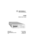
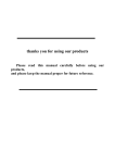
PHYSICAL DESCRIPTION
The UTA220 is manufactured as a stand-alone desktop unit
and as a rack-mount insert card. This manual applies to either
unit. Figure 1-1 shows the front panel controls and indicators.
Figure 1-1. Front Panel UTA220
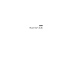
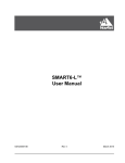
The standard UTA220 rear panel (Figure 1-2) houses two
25-pin D-type connectors for the DTE interface, an 8-pin ISDN
U modular connector (U interface), the ON/OFF toggle switch,
line fuse, and power control. The UTA220 can be ordered with
a V.35 interface, in which case adapters should be connected
to the 25-pin D-type connectors (Figure 1-3).
1-2
UTA220/UTA220k
Introduction
Caution: Connecting a V.35 DTE to a non-V.35 port may
damage the DTE.
Figure 1-2. Rear Panel EIA-232 Configuration
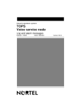
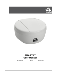
Figure 1-3. V.35 Adaptor
If the UTA220 is ordered with the additional upper ports, then
the rear panel will also contain two additional 25-pin D-type
connectors above the two lower DTE interface connectors
(Figure 1-4).
Figure 1-4. Four Port Rear Panel Configuration
UTA220/UTA220k
1-3
Introduction
LED Description
The UTA220 has six LED indicators: B1, B2, D, DP, T, PW.
The functions of these LEDs are as follows:
B1 - On when the B1 channel has a call.
B2 - On when the B2 channel has a call.
D - This LED is for the D-Channel.
• It is off when the U connection is not established.
• It single blinks when the U connection is established.
(This may take up to 15 seconds after connection is made.)
• It double blinks when communications are established with
the switch.
• It is on when all B channels are available.
DP - On when the D-Channel is available for packet
calls.
T (Test) - On during the following global tests:
• 2B+D loopback
• Switch initiated tests--quiet mode and insertion loss
measurement
PW - On when the UTA220 has power.
FUNCTIONAL
The UTA220 operates on the ISDN Basic Rate Interface (BRI)
(2B+D). This interface provides two 64-kbps full-duplex
bearer (B) channels for circuit switched lines. The Basic Rate
Interface also provides a 16 kbps delta (D) channel for
signaling messages. The UTA220 adapts any data terminal to
the ISDN Basic Rate Interface for circuit-switched data.
1-4
UTA220/UTA220k
Installation
Chapter 2
Installation
Installation of the UTA220/UTA220k is simple and straight
forward. Prior to installation, refer to Chapter 3 to either verify
or change strap options.
RECEIPT INSPECTION
After unpacking the equipment, check the contents against the
packing list. Inspect the equipment carefully for damage that
may have occurred in shipment. If there is damage or material
shortage, contact the shipping agent and Motorola for advice
and assistance. Motorola suggests that the shipping container
and packing material be retained for future shipment.
SITE PREPARATION
The installation area should be clean and free from extremes
of temperature, humidity, appreciable shock, and vibration.
Allow ample space at the rear of the UTA220 for cable
clearance and air flow. Install the UTA220 within 6 feet of a
115 or 230 VAC grounded outlet as required for the specific
model and no farther than 50 feet from the DTE.
UTA220/UTA220k
2-1
Installation
INSTALLATION
A typical installation is shown in Figure 2-1.
Figure 2-1. Typical Installation
Power Connection
Insert the power plug into a grounded 115 or 220 VAC outlet
as required for the specific model. The UTA220 is now ready
to be turned on and programmed.
Caution: Do not connect the UTA220 to the ISDN line until
the UTA220 has been programmed with the correct switch
settings. Refer to Central Office Switch in Chapter 3 for details.
ISDN Connection
To connect the UTA220 to the ISDN line, insert one end of the
supplied cable into the UTA220 ISDN U jack. Insert the other
end into the ISDN (RJ45) jack.
Note: An NT1 device is not required.
2-2
UTA220/UTA220k
Installation
DTE Connection
Insert each DTE cable into a DTE connector. Insert the
opposite end into the DTE. Secure the connect screws to
complete the connection.
DTE INTERFACE SPECIFICATIONS
The DTE interface to the UTA220 is through an EIA-232
D/E 25-pin D-type connector. The UTA220 can also be
configured for V.35 operation. It is also available with V.35
interfaces and with two additional ports for EIA-366 dialing,
or EIA-232C operation.
UTA220/UTA220k
2-3
Installation
2-4
UTA220/UTA220k
Getting Started
Chapter 3
Getting Started
This chapter provides instructions for setting switches and
straps plus a quick programming setup for the DMS100 or the
5ESS central office switch or switches running National ISDN
1 (NI1).
Caution: Do not connect the UTA220 to the ISDN line until
the UTA220 has been programmed for the correct switch,
switch version, Terminal Endpoint Identifier (TEI) numbers,
and Service Profile Identifiers (SPIDs). These are provided by
the telephone company at subscription time. Use of numbers
other than those assigned or failure to program these numbers
in the UTA220 can result in error conditions between the
central office switch and the terminal adapter.
SWITCHES AND STRAPS
The unit is factory configured to current industry standards.
Because of different environments, some terminal adapters
may require strap or switch changes. This section describes the
strap and switch options and how to use them.
Caution: Electrostatic discharge (ESD) can damage
electronic components.
Cover Removal
To select or inspect the strap option, first remove the unit’s
cover.
Warning: Do not remove the cover unless both the power cord
and ISDN line are unplugged.
Place the UTA220 on its side on a flat surface. Insert a medium
size flat screwdriver blade in one of the bottom rear latch slots.
DO NOT PUSH the screwdriver. Lightly pry the handle away
to disengage the lock prong from the lock clip as shown in
Figure 3-1. Assist by pushing the cover from the chassis with
your fingers on the unit rear edges. Repeat this procedure with
the remaining three latch slots.
UTA220/UTA220k
3-1
Getting Started
Figure 3-1. Cover Removal
To replace the cover, align the lock clips, rear guide grooves,
and front lock tabs. Press the cover in place until the lock
prongs engage the lock clip.
SWITCH AND STRAP SETTINGS
The following options are selected by switches or straps
located on the PC boards inside the UTA220 housing. To
change the strap setting, lift the jumper strap connector off and
reinsert it in the new position. Figure 3-2 shows a typical strap
application.
Figure 3-2. Typical Strap Application
Caution: Only personnel familiar with DIP switch selection
should change switch positions or the ground strap from
factory settings. Changes should be made only during setup.
Signal Ground
Signal ground is normally isolated from frame ground
(factory). If interference exists, connect signal ground to frame
ground by moving the strap.
3-2
UTA220/UTA220k
Getting Started
(Figure 3-3).
Figure 3-3. Strap and Switch Locations
V.35/EIA-232 Interface
The V.35/EIA-232 interface cards can conform to V.35
(factory) or EIA-232 D/E by means of two slide switches and
a DIP switch. Slide the switches toward the front of the
UTA220 to select V.35 and toward the rear of the UTA220 to
select EIA-232 D/E (Figure 3-4).
To complete the selection of EIA-232 D/E, set the DIP switch
as indicated in Table 3-1. The following sections describe how
to change DIP switch settings.
Table 3-1:
DIP Switch Settings for EIA232 D/E Operation
DIP Switch Position
1
2
3
4
OFF
OFF
ON
ON
UTA220/UTA220k
3-3
Getting Started
Note: Ensure that both slide switches on the interface card
are in the same position.
Figure 3-4. V.35 EIA-232 interface Card
Interface Card Removal
The port 1 V.35/EIA-232 interface card must be removed from
the UTA220 to change the DIP switch settings.
Note: Do not remove the port 2 interface card. The port 2 DIP
switch can be accessed without removing the card.
3-4
UTA220/UTA220k
Getting Started
Remove the two screws from the port 1 interface card and pull
it straight up (Figure 3-5). To re-assemble, align the interface
card to the UTA220 PC board, press down, and insert the two
screws.
Figure 3-5. V.35 Switch Location
DIP Switch Options
The V.35/EIA-232 interface card has an eight-position DIP
switch on the bottom (Figure 3-5). The port 2 DIP switch
settings can be changed without removing the port 2 interface
card. Note the orientation of the switch when changing the
settings on port 2. The DIP switch allows you to transpose the
Ring Indicate (RI) and Local Loopback pins (LL). Normally,
RI is found on pin J and LL is found on pin L. However, these
can be transposed (Table 3-2).
Table 3-2:
V.35 Ring Indicate Local Loopback Pinouts
DIP Switch Position
Pin Function
& Location
1
2
3
4
RI
LL
ON*
ON*
OFF*
J*
L*
ON
*default
UTA220/UTA220k
3-5
Getting Started
Transmit clock B can be disconnected from pin AA/2 by
turning switch position 6 to OFF. Switch positions 5, 7, 8
should be left in their factory settings (Table 3-3).
Table 3-3: V.35 Transmit Clock Pinout
DIP
Switch Position
Pin Function
& Location
5
6
7
8
TC
OFF*
ON*
OFF*
ON*
AA/2*
OFF
---
Note: Extreme care should be taken to re-align the interface
card when inserting it in the UTA220.
CENTRAL OFFICE SWITCH
The UTA220 is designed for easy programming and operation.
Using the front panel LCD display and push-button, the
UTA220 can be set up for one of the following central-office
switches:
• National ISDN-1
• NTI DMS100, BCS-30, BCS-31/32 or
• AT&T 5ESS, 5E4.2, 5E5, 5E6
Programming the UTA220 requires the following information,
which is provided by the telephone company:
• Switch type and version
• Terminal Endpoint Identifiers (TEI)
• Service Profile Identifiers (SPID)
• Directory Number (DN) strings (only supplied with National
ISDN and NTI DMS100 lines)
This information identifies the UTA220 to the telephone
company. Until the UTA220 has been programmed with this
information, the telephone company will not recognize the
terminal adapter, and calls cannot be placed.
SETUP
Caution: For proper operation of the UTA220, enter
the following options exactly as given by the
telephone company.
3-6
UTA220/UTA220k
Getting Started
Setup Step 1
Plug the UTA220 into the power outlet. Turn the power switch
on the rear panel ON.
Note: Do not connect the UTA220 to the ISDN line until the
UTA220 has been properly programmed.
The LCD displays the banner:
ISDN TERMINAL ADAPTER
Setup Step 2
To program the UTA220, perform the steps in Table 3-4. Use
the HOME key any time to back up to correct a mistake.
Table 3-4: Programming Steps
STEP
1
LCD SCREEN
DISPLAY
ISDN
ACTION
Press YES or NO key to advance to the next display.
TERMINAL ADAPTER
2
DIAL/HANGUP
OPTIONS?
Press NO.
3
STATUS DISPLAYS?
Press NO.
4
CONFIGURATION
OPTIONS?
Press YES.
5
SWITCH CONFIG
OPTIONS?
Press YES.
6
SWITCH TYPE
OPTION?
Press YES.
7
NATIONAL ISDN
CHANGE?
National ISDN
NTI DMS100
AT&T 5ESS
Press NO.
Continue programming
with STEP 9.
Press YES until "NTI
DMS100" is displayed,
then press NO.
Press YES until
"AT&T 5ESS" is
displayed, then press
NO.
8
WILL DESTROY ALL
NET OPTS, CONT?
Press YES. The display momentarily shows ’RESETTING SWITCH OPTIONS"
while it changes the switch options to the default values for the selected switch
type.
9
SWITCH TYPE OPTION?
Press NO.
10
SWITCH VERSION
OPTION?
National ISDN
NTI DMS100
AT&T 5ESS
Press No. Continue
programming with STEP
13.
Press YES.
Press YES.
11
<default version>
VERSION. CHANGE?
This screen displays the default version for the switch type you selected above.
Press YES until the correct version is displayed. Press NO to select the switch
version choice. (refer to Chapter 4, ISDN Switches section.)
12
SWITCH VERSION
OPTION?
Press NO.
13
D-CHANNEL
OPTIONS?
Press YES.
UTA220/UTA220k
3-7
Getting Started
Table 3-4: Programming Steps (Continued)
STEP
LCD SCREEN
DISPLAY
ACTION
14
D-CHANNEL PROV
OPTIONS?
Press NO.
15
D-CHANNEL
LAPD OPTIONS?
Press YES.
16
CURRENT PORT = 1
CHANGE?
Press NO.
17
P1:X.25 TEI=DIS
CHANGE?
If D-channel X.25 is desired, follow the selections described in Step 18 for entering
a TEI value. For AT&T 5ESS switches, this setting is normally "AUTO". For NT
DMS-100 and NT-1 switches, a manual TEI (0-63) value is normally required. If
D-Channel X.25 is not desired, press NO.
18
P1: DATA TEI = AUTO.
CHANGE?
There are three classes of possible DATA TEI value settings: "AUTO", "DIS", and
0-63. Use one of the setup cases below that matches your TEI value.
"AUTO"
TEI:
Press NO to advance to the next menu. The "AUTO"
value is used to select a dynamically assigned TEI.
"AUTO" is the factory default and should be correct
in most situations.
"DIS"
TEI:
Press YES to scroll through the supported TEI
values until "DIS" is displayed. Press NO to advance
to the next menu.
0-63
(UTA220k):
Press YES twice "00" is displayed. Press the keypad
number keys until the entire number has been keyed
in. If the number is one digit long, press the
appropriate number key, then press ENTER.
0-63
(UTA220):
Press YES until the first digit of the value is displayed
then press NO to accept the digit and advance to
the next digit. Continue to do this until the entire
number has been keyed in. If the number is one digit
long, enter the first digit, then press YES until the
character "_" is displayed to the right of the digit.
Press NO to enter the TEI number.
Note: If only one circuit-switched call at a time is necessary and the call will always
be placed to or from the same Directory Number, then only one of the TEIs should
be enabled and the other disabled.
19
P1:_____________
SPID.
CHANGE?
- The SPID only needs to be configured if the TEI is not disabled.
- Enter the SPID string in the same manner as the TEI. The SPID value can be up
to 20 digits in length.
20
P1:_____________
DN.
CHANGE?
- The Directory Number (DN) only needs to be configured if the TEI is not disabled.
The DN is optional for AT&T 5ESS switch types.
- Enter the DN string in the same manner as the TEIs and SPIDs. Like the SPID
strings, the DN strings can be up to 20 digits in length.
21
CURRENT PORT = 1
CHANGE?
Press 2.
22
P2: X.25 TEI=DIS
CHANGE?
Press NO
23
P2: DATA TEI = AUTO
CHANGE?
Same as Step 18.
24
P2:_____________
SPID.
CHANGE?
- The SPID only needs to be configured if the TEI is not disabled.
- Enter the SPID string in the same manner as the TEI. The SPID value can be up
to 20 digits in length.
25
P2:_____________
DN.
CHANGE?
- The Directory Number (DN) only needs to be configured if the TEI is not disabled.
The DN is optional for AT&T 5ESS switch types.
- Enter the DN string in the same manner as the TEIs and SPIDs. Like the SPID
strings, the DN strings can be up to 20 digits in length.
26
3-8
If you have a two-port unit, then continue with STEP 37.
UTA220/UTA220k
Getting Started
Table 3-4: Programming Steps (Continued)
STEP
LCD SCREEN
DISPLAY
ACTION
27
CURRENT PORT = 2
CHANGE?
Press 3.
28
P3:
X.25
CHANGE?
Press NO
29
P3: DATA TEI = DIS.
CHANGE?
Same as Step 18.
30
P3:_____________
SPID. CHANGE?
- The SPID only needs to be configured if the TEI is not disabled.
- Enter the SPID string in the same manner as the TEI. The SPID value can be up
to 20 digits in length.
31
P3:_____________
DN.
CHANGE?
- The Directory Number (DN) only needs to be configured if the TEI is not disabled.
The DN is optional for AT&T 5ESS switch types.
- Enter the DN string in the same manner as the TEIs and SPIDs. Like the SPID
strings, the DN strings can be up to 20 digits in length.
32
CURRENT PORT = 3
CHANGE?
Press 4.
33
P4: X.25 TEI=DIS
CHANGE?
Press NO
34
P4: TEI = DIS.
CHANGE?
Same as Step 18.
35
P4:_____________
SPID. CHANGE?
- The SPID only needs to be configured if the TEI is not disabled.
- Enter the SPID string in the same manner as the TEI. The SPID value can be up
to 20 digits in length.
36
P4:_____________
DN.
CHANGE?
- The Directory Number (DN) only needs to be configured if the TEI is not disabled.
The DN is optional for AT&T 5ESS switch types.
- Enter the DN string in the same manner as the TEIs and SPIDs. Like the SPID
strings, the DN strings can be up to 20 digits in length.
37
CURRENT PORT = 4
CHANGE?
Press HOME.
38
D-CHANNEL LAPD
Press NO.
TEI=DIS
OPTIONS?
39
D-CHANNEL PROVISION
X.25 OPTIONS?
Press NO.
40
D-CHANNEL OPTIONS?
Press NO.
41
MULTIFRAME SYNC =
__________CHANGE?
Press NO.
42
FRONT PANEL LOCK
OPTION?
Press NO.
43
SAVE SWITCH AND
GLOBL TO NONVOL?
Press YES to save the switch configuration. The display momentarily shows
"SAVING" while it is saving the options to nonvolatile memory.
44
RESTART NETWORK
LINK?
Plug telephone cable into ISDN U jack on rear of unit, then press YES.
Note: Some LCD screen displays require different actions
depending on the telephone company’s switch type.
Setup Step 3
Insert the ISDN line into the ISDN U jack located on the rear
panel.
UTA220/UTA220k
3-9
Getting Started
3-10
UTA220/UTA220k
ISDN
Chapter 4
ISDN
This chapter provides information to help you set up and use
your Terminal Adaptor (TA). For users unfamiliar with TAs,
some fundamental Integrated Services Digital Network
(ISDN) concepts are presented first. If you are already familiar
with ISDN you may skip over this section, but the ISDN
Switches and the ISDN Addresses and Identifiers sections
contain information pertinent to the switch configuration of the
TA and should be reviewed.
ISDN BASICS
ISDN is a global system that provides a variety of high-speed
digital telecommunication services including voice, data,
images, and video, integrated on one network. As ISDN
evolves it will provide the same types of services as the existing
analog networks (voice and low-speed data), plus new services
made possible by recent advances in computers and digital data
communications.
ISDN is based on standards that define the interfaces between
the network and the equipment connected to it. This
standardization permits communication between ISDN
systems and equipment manufactured by different vendors
world wide.
ISDN Standards
ISDN standards are set by the International Consultative
Committee for Telegraph and Telephone (CCITT), an
organization that establishes communications
recommendations under the auspices of the United Nations.
Because ISDN technology advances faster than the CCITT can
establish standards, a number of de-facto standards have been
developed by manufacturers of telephone equipment. While
these set the precedence for CCITT standards eventually
agreed to, there are enough differences that those who set up
ISDN equipment (such as TAs) must be aware of them.
National ISDN
The U.S.A. and Canada have an ISDN standard for North
America called National ISDN. The first version of this
standard, National ISDN One (NI-1), is being adopted by
equipment manufacturers and network providers. When fully
deployed, NI-1 will make understanding and configuring
ISDN equipment easier and more efficient.
UTA220/UTA220k
4-1
ISDN
Basic Rate Interface
Several types of ISDN network services are available. The
most common is Basic Rate Interface (BRI). BRI provides two
B-channels (bearer channels) and one D-channel (used to place
and release calls on the network).
B-channels, which operate at 64 kbps full-duplex, carry endto-end data between network terminals. B-channels can be
either circuit-switched (dial-up), allowing each call to be
placed to different endpoints, or permanently connected
(nailed) to a single endpoint. In some applications, B-channels
can also be used to carry packet-switched data, where each
frame of data can dynamically be sent to different network
users. The TA does not support packet-switching on a
B-channel.
The D-channel is primarily a control channel between the
network and the terminal device (such as a TA).
Terminal Adapters
Terminal adapters attach standard data terminals and voice
telephones to the ISDN, allowing them to send and receive
calls and data via the ISDN. Some terminal adapters (but not
the UTA220) support voice service, allowing a standard
(analog) telephone set to be connected to the ISDN.
The UTA220 operates on the ISDN BRI. It provides circuitswitched data communications using circuit-switched
B-channels for data, and uses the D-channel for signaling only.
ISDN Basic Rate Interface Points
BRI points and the associated devices found on customer
premises are shown in Figure 4-1. The boxes in the diagram
represent devices, and the vertical lines represent defined
interface points. There are two types of DTEs represented in
the diagram:
• TE1 devices have a built in ISDN interface.
• TE2 devices do not have a built in ISDN interface, and
require a TA to interface with the ISDN.
The data terminal devices (DTEs) are located in the left of the
diagram. The TA is connected to the ISDN at the U interface.
An NT1 device is not required; the NT1 function is built into
the UTA220.
4-2
UTA220/UTA220k
ISDN
ISDN Service
Figure 4-1. ISDN Devices and Reference Points
To use the ISDN, you must subscribe to a network service. The
available options depend on the carrier (telephone company),
but some generally available options are:
• Types of calls supported (voice, data, packetized data)
• Circuit-switched (dial-up) or permanent (nailed) lines
• One or two B-channels
• A telephone number for each B-channel, or one number for
both channels
ISDN SWITCHES
The device controlling the ISDN line is the central office
switch. It is usually owned by the network provider (e.g., the
telephone company). Each switch has its own format and
procedures for the D-channel protocols used to establish and
control calls. (More on D-channel protocols later.) There are
three main ISDN switch standards used in North America:
AT&T, Northern Telecom (NTI), and NI-1. Their basic
functions are similar, but each has its own set of special
features and parameters.
Before using the TA, you must configure the unit for a switch
type. The TA will operate with AT&T, Northern Telecom
(NT), or any switch running National ISDN-1. Central Office
(CO) switches can be loaded with different software versions.
The TA supports AT&T switches running versions 5E4.2 and
later, and NT switches running versions BCS29 and later.
UTA220/UTA220k
4-3
ISDN
AT&T switches define Single Term and Multiple Term modes
of operation for the TA. AT&T switches support Point-toPoint, Multi-Point services and NI operation depending on the
software version loaded in the switch. The switch can also
operate in custom mode to support modes other than the
default. Table 4-1 shows AT&T switch versions, supported
modes, and default modes.
Table 4-1: AT&T Switch Modes
Switch Version
Default Mode
Custom Mode
5E4.2
Point-to-Point
None
5E5
Multi-Point
Point-to-Point
5E6
Multi-Point
Point-to-Point
5E7
Multi-Point
Point-to-Point
5E8
NI1
Point-to-Point
and Multi-Point
5E9
NI1
Point-to-Point
and Multi-Point
When you set the TA for Point-To-Point switch operation, it
runs in the single term mode and only one TA may be attached.
Because only one TA is attached, Service Profile Identifiers
(SPIDs) and Directory Numbers (DNs) are not needed to
identify the TA. This is called non-initializing mode. This
mode functions on a multi-point switch; however, the switch
requires the TA to present its DN when it makes calls to
distinguish it from other TAs on the line. Thus the DN must
be properly configured in the TA in this instance.
Normally on a multi-point line, you configure the TA for
multi-point operation. This causes the TA to run in the
multi-terminal-initializing mode; SPID numbers are required.
To configure the TA for NI1 operation, select NI1 as the switch
type.
Note: If you are using BONDING with the secondary call port,
the DN must be entered so that it can be provided to the remote
TA.
4-4
UTA220/UTA220k
ISDN
NT switches support three Protocol Version Control Issue
Codes (PVCICs), depending on the software version loaded in
the switch. Refer to Table 4-2.
Table 4-2: Northern Telecom Switch Modes
Switch Version
Default Mode
Other Modes
BCS29
PVCIC=0
None
BCS30
PVCIC=0
None
BCS31
PVCIC=1
PVCIC=0
BCS32
PVCIC=1
PVCIC=0
BCS33
PVCIC=1
PVCIC=0
BCS34
PVCIC=2
PVCIC=0, 1
BCS35
PVCIC=2
PVCIC=0, 1
BCS36
PVCIC=2
PVCIC=0, 1
Set the Switch Version option on the TA according to Table
4-3.
Table 4-3: UTA220 Switch Settings
PVCIC
TA Switch
Type
TA Switch Version
0
NTI
DMS100
DMS100 PVC-IC0
1
NTI
DMS100
DMS100 PVC-IC1
2
National
ISDN
N/A
ISDN ADDRESSES AND IDENTIFIERS
The TA contains several stored numbers–SPID, DN, and TEI
(Terminal Endpoint Identifier)–used by the network to identify
the TA.
Each logical ISDN link has an SPID that defines the profile of
services and parameters used by the terminal. The SPID is
selected by the network carrier and must be configured into the
TA before it can be used. The SPID is a string of characters or
digits, depending on the switch.
The DN is part of the service profile and is analogous to the
telephone number on the standard telephone network. The DN
identifies incoming calls. On some switches (NTI and NI-1),
the DN must also be configured into the TA; on other switches
(AT&T), the DN is not required.
UTA220/UTA220k
4-5
ISDN
The TEI is used to identify the terminal device. In most
applications, the network switch automatically assigns a TEI
to the TA when the connection is established; otherwise, you
must enter the TEI before connecting to the network.
If your switch permits it, the UTA220 allows you to use one
SPID and one TEI on simultaneous calls. AT&T switches
allow two calls per SPID. With this support you can configure
two or more ports to share a DN.
Note: To use this feature, configure each port with the same
SPID and DN, enable one port’s TEI, and disable the TEI on
the remaining port(s).
The UTA220 also allows you to use multiple DNs on the same
SPID if your switch supports it. NT switches support up to four
DNs per SPID.
Note: To use this feature, configure both ports with the same
SPID and different DNs, then enable one port’s TEI and disable
the other’s.
ISDN CHANNELS
As previously mentioned, there are three channels available on
the ISDN Basic Rate Interface: two 64 Kbps B-channels and
one 16 Kbps D-channel. The B-channels are the primary means
of carrying user information, whether voice or data. Voice data
must be sent on a B-channel. The B-channel also provides the
most efficient path for data communications, since it has four
times the data capacity of the D-channel.
The D-channel is the control channel between the TA and the
network switch. It is used mainly for exchanging signaling
messages with the switch, to perform functions like setting up
and releasing calls.
Note: The UTA220 supports only data calls.
B-Channel Data Service
When a B-channel data call is placed, the switch allocates a
free B-channel between the TA and the remote DCE (e.g., the
TA at the other end of the ISDN link). This B-channel acts like
a bit-pipe between two network users, operating
synchronously at 64 Kbps. In most cases, the ISDN network
does not know about the format of the data sent on the
B-channels.
There are several ways to use the B-channel to pass data. In
the “clear channel” mode, data from the DTE goes directly
onto the B-channel. However, to use this mode, your DTE must
also operate synchronously at 56 or 64 kbps.
4-6
UTA220/UTA220k
ISDN
B-Channel Data Protocols
To allow greater flexibility for your DTE, there are three rate
adaption protocols available for use on the B-channel: TLink,
V.120, and Bonding. These protocols allow your DTE to
operate both synchronously and asynchronously, and at a
different speed than the B-channel.
• TLink is a Northern Telecom proprietary rate adaption
protocol. It supports synchronous and asynchronous rate
adaption at a variety of speeds.
• V.120 is a CCITT protocol that supports synchronous and
asynchronous rate adaption, and also provides link-layer
error control. Although errors on a digital network are more
rare than on an analog telephone line, they are possible.
V.120 provides an end-to-end protocol for detecting and
correcting any such errors. V.120 also performs buffering
and can thus support flow control to and from the DTE.
• BONDING is a new protocol standard from the Bandwidth
ON Demand INteroperability Group. It combines the
bandwidth of several 56 kbps or 64 kbps channels, and can
bond from 2 to 31 channels at once, if the channels are
available. The high speed data, which must be a multiple of
56 kbps or 64 kbps, comes in on the DTE interface and is
split to the various channels. On the opposite end the data is
recombined into the original data stream and sent to the DTE
interface.
To use a rate adaption protocol, the DCEs (e.g., TAs) at both
ends of the link must support it and must be configured to use
it. In general, since it is more flexible and supports error
control, V.120 should be used for most applications, and thus
it is the default protocol in the UTA220.
D-Channel Signaling Protocols
The D-channel conveys signaling information and, optionally,
packet-switched data, to the network switch. This data is
passed in message blocks defined by the ISDN signaling
protocols. These protocols vary somewhat depending on the
network switch installed at the telephone company's central
office. As mentioned earlier, several de-facto protocol
standards, are used for the D-channel signaling between the
TA and the switch.
The TA signaling protocols function on three protocol layers.
Each of these layers is described below.
Layer One
The physical layer includes components and interfaces needed
to provide a physical communications path. All ISDN switches
use the same physical layer protocols for the Basic Rate
Interface, which are based on CCITT Recommendation I.430.
UTA220/UTA220k
4-7
ISDN
Layer Two
The data link layer ensures error-free transmission of
D-channel messages between the terminal and the network
switch. The link layer in effect provides a virtual error-free
connection for the next higher protocol layer to use. The LAPD
protocol is the error detection and correction mechanism for
layer two. Layer two protocols are based on CCITT
recommendation Q.921, and are almost identical. Minor
differences do exist, however, primarily in how the protocols
respond to certain very unlikely error conditions.
Layer Three
The network layer consists of signaling messages passed
between the terminal and the network, using the data link layer.
These messages communicate call setup (dialing) and release
messages from the TA, call progress information from the
network, and messages concerning special call-related
features. Layer three of the D-channel can also be used to
exchange packetized data using X.25, if the TA and the switch
are set up to allow it.
All layer three protocols are based on CCITT
Recommendation Q.931. However, the protocol used depends
on the brand and version of the network switch. There are
differences in the exact procedures used by each switch to set
up and release calls. In addition, because switches are
manufactured by competing companies, each switch offers a
different set of extra features. These features are called
supplementary services.
Unfortunately, each vendor implements these features
differently. Also, there are different versions of each of the
switches, each of which implements a different set of features.
As a result, you must configure your TA for the particular
switch type and version so that the TA can use the correct
signaling protocol for that switch. The switch type and version
are two of the most important network parameters in the TA.
4-8
UTA220/UTA220k
LCD Operation
Chapter 5
LCD Operation
The UTA220 has an easy-to-use front panel with a Liquid
Crystal Display (LCD). You can monitor TA status, perform
operations, and program the TA without using a terminal or
computer.
LCD MENUS
The LCD menus are arranged in multiple levels. Menu headers
may to more menu headers, options screens or action screens.
When the NO key is pressed while a menu header is displayed,
the LCD advances to the next menu header. When the YES
key is pressed, the menu descends one level in the menus.
Main Menus
The Main Menu headers are:
• DIAL/HANGUP OPTIONS? - to dial manually or to dial
previously stored telephone numbers and to hang up.
• STATUS DISPLAYS? - to view the status of each data port
call.
• CONFIGURATIONS OPTIONS? - to program switch and
port options.
• CONFIGURATION LOAD/SAVE OPTIONS? - to save the
switch and port configuration settings or to retrieve the
factory settings or stored settings.
• DIAGNOSTIC OPTIONS? - to run tests, restart the network
and view product information.
Submenus
A menu includes menu headers, action screens, or option
screens. Action screens let you perform an action, such as
dialing. Option screens show settings and allow changes.
Options may be set from multiple choice lists or by entering
data.
LCD OPERATION
Menu Traversal
After power-up, the LCD displays the sign-on banner: ISDN
TERMINAL ADAPTER. To enter the Main Menu level, press
the YES or NO key. Whenever the LCD is on the Main Menu
level, the sign-on banner can be displayed by pressing HOME.
In general, pressing NO moves the display vertically down a
column (Table 5-1) and pressing YES moves the display
horizontally across the columns (one level deeper).
UTA220/UTA220k
5-1
LCD Operation
At the last Main Menu screen, pressing NO displays the first
Main Menu screen. At the last screen at any other level,
pressing NO moves the display up one level.
The deepest screen (rightmost, in the table) typically changes
an option or performs an action. Pressing YES at this screen
begins the change process on the option, or performs an action.
Table 5-1. Menu Option Summary
Main Level
Level 1
Level 2
Level 3
Level 4
Description
ISDN
TERMINAL
ADAPTER
DIAL/HANGUP
OPTIONS?
Current Port:
n
Pn:ENTER
Pn:---------NUMBER TO
ENTER#.
DIAL?
CHANGE
n=current port. Note 2
Pn:REDIAL? x
n=current port
Pressing Call/Hangup from
anywhere in menu advances to
ENTER NUMBER screen
x=last number dialed. Note 2
Pn:DIAL
Pn:DIAL TEL #t?
STORED NUM- s
BER?
n=current port
s =stored number t=0-9 storage
index. Note 2
Pn:VIEW/
Pn:x. Tel
CHANGE
CHANGE?
STO RED TEL
NUM?
n=current port
#t.
x= 13 digits of the phone number. Phone number can contain
40 digits, scrolled 1 digit / sec.
t=0-9 storage index. Note 3
Pn: HANGUP?
n=current port. Note 2
STATUS
Current Port= n.
n=current port
DISPLAYS?
Change?
CALL STATUS SCREEN
s =IDLE, SETTING UP,
DIALING, PROCEEDING,
RINGING, ECHO
CANCELING ONLINE,
INCOMING CALL,
ANSWERING,
D I SC O N N E C TI N G , B U SY ,
DISCONNECTED
OR
Pn:ONLINE
prmd
p=CLEAR, BOND, T-LINK,
V.120
m=SYNC-1, SYNC-2, ASYNC
r =300, 1200, 2400, 4800, 9600,
1k, 38k, 48k, 56k, 57k, 64k,
112k, 128k
d=8E, 8O, 8N, 7E, 7O, 7N, 7M
This screen appears once a call
is connected. Note 4
C O N F I G U R A - SWITCH
TION
CONFIG
OPTIONS?
OPTIONS?
SWITCH TYPE x.CHANGE?
OPTION?
x=NATIONAL ISDN, NT
DMS100,
AT&T
5ESS
SELECTED
WILL DESTROY R E S E T T I N G
The query appears only if the
NET
OPTS, SWITCH
O P - network type has changed.
CONT?
TIONS
SWITCH
x
VERSION.
CHANGE?
VERSION
x=DMS100 PVC IC-0, DMS100
PVC IC-1 (if switch type = NT)
OPTION?
Navigation button
directions:
5-2
YES
x=5ESS MULTIPOINT, 5ESS
PT TO PT, (if switch type=ATT)
NO
HOME
UTA220/UTA220k
LCD Operation
Table 5-1. Menu Option Summary (Continued)
Main Level
Level 1
Level 2
Level 3
Level 4
Description
SWITCH
B-CHANNEL
OPTIONS?
B-CHANNEL
PROV
B1 = x
x= NONE, PERMANENT
CONFIG
CHANGE?
OPTIONS?
OPTIONS?
(cont.)
B2 = x
x= NONE, PERMANENT
CHANGE?
D-CHANNEL OP- D - C H A N N E L
TIONS?
PROV
D-CHAN PROVI- x= NONE, X.25
SION x. CHANGE?
OPTIONS?
D-CHANNEL
LAPD
CURRENT PORT n=1 or 2
= n. CHANGE?
OPTIONS?
Pn:X.25 TEI = x. n=CURRENT PORT
CHANGE?
x= 0-63, DIS, AUTO
Pn:DATA TEI =x n=CURRENT PORT
CHANGE?
x= 0-63, DIS, AUTO
Pn:x
S P I D . n=CURRENT PORT
CHANGE?
x=SPID, up to 20 digits
Pn:
x
CHANGE?
D-CHAN
PROVISION
X.25
D N . n=CURRENT PORT
x=DN, up to 20 digits
RX
W I N D O W x=1 - 7
SIZE=x.
CHANGE?
OPTIONS?
TX
W I N D O W x=1 - 7
SIZE=x.
CHANGE?
RX
P A C K E T x=128, 256
SIZE=x.
CHANGE?
TX
P A C K E T x=128, 256
SIZE=x.
CHANGE?
PVC NUMBER =x x=0 - 255
CHANGE?
I N C L O G I C A L x=0 - 255
CHAN NUM=x.
CHANGE?
2-WAY
L O G x=0 - 255
CHAN NUM=x.
CHANGE?
O U T L O G I C A L x=0 - 255
CHAN NUM=x.
CHANGE?
SEQUENCE NUM- x=8, 128
BER MOD=x.
CHANGE?
FRONT PANEL ENTER PASSLOCK
WORD ------CHANGE?
OPTION?
Enter password to gain access
to lock option screen.
FRONT PANEL
LCK
=
x
CHANGE?
x= UNLOCKED, OPTIONS,
OPT/ACT
SAVE SWITCH SAVING
AND GLOBL TO
NONVOL?
Navigation button
directions:
YES
NO
HOME
UTA220/UTA220k
5-3
LCD Operation
Table 5-1. Menu Option Summary (Continued)
Main Level
Level 1
Level 2
Level 3
Level 4
PORT CONFIG C U R R E N T
OPTIONS?
PORT=n
CHANGE?
Description
n=1 - 2
Pn:LOAD FROM
Pn:LOAD FROM LOADING
n=current port
NONVOL?
NONVOL
CHANGE?
x= 0, 1
Pn:LOAD FROM
Pn:LOAD
FACTORY
PROFILE?
FACTORY
PROF
CHANGE?
x.
LOADING
x= 0, 1
x.
P n : A N S W E R Pn:AUTO
OPTIONS?
ANSWER=x
CHANGE?
Pn:DTE
OPTIONS?
n=current port
n=current port
x= ON, OFF
Pn: RINGS
n=current port
UNTIL ANS =x.
CHANGE?
x= 0 - 255
Pn:xxx.
CHANGE?
n=current port
Pn:DTE SPEED
=xxx
CHANGE?
n=current port
Pn:WORD
LENGTH=
CHANGE?
n=current port
x= SYNCHRONOUS 1,
SYNCHRONOUS 2, ASYNCHRONOUS
n=300, 1200, 2400, 4800, 9600,
19.2k, 38.4k, 48k, 56k, 57.6k,
64k, 112k, 128k
x
x= 7, 8
Pn:PARITY=x.
CHANGE?
n=current port
Pn:
n=current port
CHARACTER
ECHO = xxx.
CHANGE?
x= OFF, ON
Pn: X25XPAR=x.
CHANGE?
n=current port
Pn:
DTE
GUARD=
x.
CHANGE?
n=current port
P n: D T E C M D P n : D I A L E R
AND
CMDs
=
x.
CHANGE?
MESSAGE
n=current port.
OPTIONS?
for ports 3-4: x=NONE, AT, PAD,
PAD D, EIA-366
Pn: AT
x= NONE, EVEN, ODD, MARK
x=YES, NO
x= OFF, ON
for ports 1-2: x=NONE, AT, PAD,
PAD D, V25 BCS, V25 HDLC
Pn: STATUS DIS- n=current port
PLAY
x . x=ON, OFF, ANS OFF
CHANGE?
OPTIONS?
Pn:MSG
FORMAT=
CHANGE?
n=current port
x . x=VERBOSE, NUMERIC
Pn:RESULT
n=current port
CODES OPT=x. x= OFF, ON
CHANGE?
P n : C O N N E C T n=current port
MSGS
=
x . x= BASIC, ALL, BUSY
CHANGE?
Navigation button
directions:
5-4
YES
NO
HOME
UTA220/UTA220k
LCD Operation
Table 5-1. Menu Option Summary (Continued)
Main Level
Level 1
Level 2
Level 3
Level 4
C O N F I G U R A - PORT CONFIG P n: D T E C M D Pn: AT
TION
O P - O P T I O N S ? ? AND
OPTIONS?
TIONS? (cont.) (cont.)
(cont.)
MESSAGE
Description
Pn:
E S C A P E n=current port
CHAR=x.
x= 0 - 127; 128-255 disabled
CHANGE?
OPTIONS? (cont.)
Pn:CR CHAR=x. n=current port
CHANGE?
x= 0 - 127
Pn:LF CHAR=x. n=current port
CHANGE?
x= 0 - 127
Pn:BS CHAR=x. n=current port
CHANGE?
x= 0 - 127
Pn:GUARD
TIME=x.
CHANGE?
n=current port
x= 0 - 255
Pn: X.3 PARMS? Pn:SESSION = s. n=current port
CHANGE?
s=1-4
PnSsR1:PAD
n=current port
RECAL CHAR=x.
s = current session
CHANGE?
x= 000 - 126
PnSsR2:ECHO =x. n=current port
CHANGE?
s = current session
x= ENABLE, DISABLE
P n S s R 3 : D A T A n=current port
FWD CHAR = x. s = current session
CHANGE?
x= 0, 2, 126
PnSsR4:IDLE
n=current port
TIME DELAY = x. s = current session
CHG?
x= 0-127
P n S s R 5 : A N C I L n=current port
D E V C T L = x . s = current session
CHANGE?
x =NONE, DATA, DATA CMD
PnSsR6:PAD
n=current port
SERV
S I G = x . s = current session
CHANGE?
x= SUPRESS, ALL-PRM,
PROMPT, ALL
P nSs R 7: B RE AK n=current port
S I G A C T = x . s = current session
CHANGE?
x= 00 - 37
PnSsR8:
n=current port
D I S C A R D = x . s = current session
CHANGE?
x= NORMAL, DISCARD
PnSsR9:PAD
n=current port
A F T E R C R = x . s = current session
CHANGE?
x= 000 - 255
P n S s R 1 0 : L I N E n=current port
FOLDING=x.
s = current session
CHG?
x= 000 - 255
P n S s R 1 1 : P A D n=current port
DTE
S P E E D = s = current session
x.CHG?
x= 300, 600, 1200, 2400, 4800,
9600, 19200, 38400
P n S s R 1 2 : P A D n=current port
F L O W C T L = x . s = current session
CHG?
x= OFF, ON
PnSsR13:LF INS n=current port
A F T E R C R = x . s = current session
CHG?
x= 0 - 7
Navigation button
directions:
YES
NO
HOME
UTA220/UTA220k
5-5
LCD Operation
Table 5-1. Menu Option Summary (Continued)
Main Level
Level 1
Level 2
Level 3
Level 4
Description
P n S s R 1 4 : P A D n=current port
AFTR
L F = x . s = current session
CHANGE?
x= 000 - 255
Navigation button
directions:
5-6
YES
NO
PnSsR15:
n=current port
EDITING=x.
CHANGE?
s = current session
HOME
UTA220/UTA220k
x= ENABLE, DISABLE
LCD Operation
Table 5-1. Menu Option Summary (Continued)
Main Level
Level 1
Level 2
Level 3
Level 4
Description
C O N F I G U R A - PORT CONFIG P n: D T E C M D Pn: X.3 PARMS? P nSs R 16: C H AR n=current port
(cont.)
TION
O P - O P T I O N S ? ? AND
D E L C H A R = x . s = current session
TIONS? (cont.) (cont.)
CHANGE?
MESSAGE
x= 000 - 127
OPTIONS? (cont.)
P n S s R 1 7 : L I N E n=current port
D E L C H A R = x . s = current session
CHANGE?
x= 000 - 127
P n S s R 1 8 : L I N E n=current port
DIS
C H A R = x . s = current session
CHANGE?
x= 000 - 127
P n S s R 1 9 : E D I T n=current port
SRV SIG =x.CHG? s = current session
x= NONE, PRINTER, DISPLAY
PnSs R 20: ECH O n=current port
MASK=x.
s = current session
CHANGE?
x= 000 - 255
PnSsR21:PARITY n=current port
CHECK=x.
s = current session
CHANGE?
x= YES, NO
P nS s R 2 2: P A G E n=current port
WAIT
=
x . s = current session
CHANGE?
x= 000 -255
Pn:DTE PIN
OPTIONS?
Pn: ISDN
PROTOCOL
OPTIONS?
Pn:DTR
PIN
OPT=
x.
CHANGE?
n=current port
Pn:DSR
PIN
OPT=
x.
CHANGE?
n=current port
Pn:DCD PIN
OPT=
x.
CHANGE?
n=current port
Pn:CTS
PIN
OPT=
x.
CHANGE?
n=current port
Pn:DCD DROP
TIME=x.
CHANGE?
n=current port
Pn:DTR
DETECT TIME=x.
CHANGE?
n=current port
Pn:RTS TO CTS
TIME=x.
CHANGE?
n=current port
Pn:PROTOCOL=a.
CHANGE?
n=current port
Pn:RATE
n=current port
MULTIPLR=a.
CHANGE?
a = 1,2
Pn:FLOW CON- PN:x.FLOW CTL.
TROL
CHANGE?
OPTIONS?
n=current port
x= IGNORE, RCAL ACU, HANG
UP, RELOAD, DIAL
x= ON, NORMAL
x= ON, NORMAL, DISC OFF
x= RTS, ON
x= 000 -255
x= 000 -255
x= 000 -255
a = V.120, X.25, Clear, TLink,
Bond
x= NO, UNI CTS, BI RTS/CTS,
BI XON/XOFF
Pn:RESET FLOW n=current port
CTL
=
x . x= EN, DIS
CHANGE?
Navigation button
directions:
YES
NO
HOME
UTA220/UTA220k
5-7
LCD Operation
Table 5-1. Menu Option Summary (Continued)
Main Level
Level 1
Level 2
C O N F I G U R A - PORT CONFIG Pn: ISDN
TION
OP- OPTIONS? ? PROTOCOL
TIONS? (cont.) (cont.)
OPTIONS?
Level 3
Level 4
Pn:V.120
Pn:MAX
T X n=current port
FRAME SIZE=x. x= 1-260
CHANGE?
OPTIONS?
Description
(cont.)
Pn:MAX
R X n=current port
FRAME SIZE=x. x= 1-260
CHANGE?
Pn:WINDOW SIZE n=current port
= x.
CHANGE? x= 1-127
Pn:T200 TIMER= n=current port
x.
x= 1-255
CHANGE?
Pn:INFO
SLCT=x.
CHANGE?
Pn:TLINK
F R M n=current port
Pn:x. CHANGE?
OPTIONS?
Pn:SESSION
OPTIONS?
x= I Frame, UI Frame
n=current port
x= ADAPTIVE MODE, FIXED
MODE
Pn:DTR=x.
CHANGE?
n=current port
Pn: RTS=x.
n=current port
CHANGE?
x= ASSERT, NORMAL
Pn:SESSION =s.
CHANGE?
x= ASSERT, NORMAL
n=current port
s=1-4
PnSs:X.25
PnSs:RX
OPTIONS?
WINDOW SIZE=x. s = current session
CHANGE?
x= 0 - 8
PnSs:TX
n=current port
n=current port
WINDOW SIZE=x. s = current session
CHANGE?
x= 0 - 8
PnSs:RX
n=current port
PKT
S I Z E = x . s = current session
CHANGE?
x= 0, 128, 256, 512, 1024
PnSs:TX
n=current port
P K T S I Z E = x . s = current session
CHANGE?
x= 0, 128, 256, 512, 1024
PnSs:PVC
n=current port
OPTION=x.
CHANGE?
s = current session
x= PVC, NON-PVC
PnSs: LOGICAL n=current port
CHN
N U M = x . s = current session
CHANGE?
x= 000 - 255
PnSs:D BIT CONF n=current port
= x.
CHANGE? s = current session
x= ON, OFF
PnSs:CUG
n=current port
OPTION=x.
CHANGE?
s = current session
PnSs:CUG
NAME=x.
CHANGE?
n=current port
x= NONE, BASIC, OUTGOING,
BILAT
s = current session
x= Closed User Group Name
P n S s : R E V E R S n=current port
C H R G O P T = x s = current session
CHANGE?
x= DIS, EN
Navigation button
directions:
5-8
YES
NO
HOME
UTA220/UTA220k
LCD Operation
Table 5-1. Menu Option Summary (Continued)
Main Level
Level 1
Level 2
C O N F I G U R A - PORT CONFIG P n : S E S S I O N
TION
O P - O P T I O N S ? ? OPTIONS?
(cont.)
TIONS? (cont.) (cont.)
Level 3
Level 4
Description
PnSs:X.25
PnSs:RX
n=current port
OPTIONS?
(cont.)
THRUPUT=x
CHANGE?
s = current session
PnSs:TX
n=current port
THRUPUT=x
CHANGE?
s = current session
x= 0, 75, 110, 300, 600, 1200,
2400, 4800, 9600, 19200,
48000, 64000
x= 0, 75, 110, 300, 600, 1200,
2400, 4800, 9600, 19200,
48000, 64000
x
P n S s : N U I . n=current port
CHANGE?
s = current session
x= NUI, up to 16 digits
x P n S s : R P O A . n=current port
CHANGE?
s = current session
x= RPOA, up to 16 digits
P n S s x : U S E R n=current port
DAT.
s = current session
CHANGE?
x= User Data, up to 12 digits
PnSs:TRANST
DELY=x.
n=current port
CHANGE?
x= 00000-65535
PnSs:PKT
n=current port
s = current session
RST/CLR TMR=x. s = current session
CHANGE?
x= 000 - 600
PnSs:PKT
n=current port
C A L L T M R = x . s = current session
CHANGE?
x= 000 - 600
PnSs:AUTO
n=current port
A CC EP T VC =x . s = current session
CHANGE?
x= EN, DIS
Pn:CALL
SETUP
Pn:
ISDN
SPEED=x BPS.
OPTIONS?
CHANGE?
Pn: PERSIST DIAL=x.
n=current port
x=64K, 56K
n=current port
x=ENABLED, DISABLED
CHANGE?
Pn:
n=current port
ORIGINATE AS
x. CHANGE?
x= DATA, AUDIO, SPEECH
Pn:ANS DATA x.
CHANGE?
n=current port
Pn:ANS
AUDIO
CHANGE?
n=current port
x.
Pn:ANS
SPEECH
CHANGE?
x.
Pn:DIAL
CHANGE?
x
YES
NO
x= ENABLED, DISABLED
n=current port
x=ENBLOC, OVERLAP
n=current port
x= OFF, ON
x.
P n: W AI T F O R
CONN=
x.
CHANGE?
Navigation button
directions:
x= ENABLED, DISABLED
n=current port
Pn:ECHO
DISABLE
TONE=
CHANGE?
x= ENABLED, DISABLED
n=current port
x= 0-255
HOME
UTA220/UTA220k
5-9
LCD Operation
Table 5-1. Menu Option Summary (Continued)
Main Level
Level 1
Level 2
Level 3
Level 4
Pn: SAVE TO Pn:SAVE
NONVOL?
NONVOL
CHANGE?
TO
x.
SAVING
n=current port
x= 0, 1
SAVE
SAVE SETUP
TO NONVOL x.
COMPLETE
SETUP TO NON- CHANGE?
VOL?
SAVING
x= 0, 1
LOAD
AL L LOAD PORTS
P O R T S F R O M FROM
NONVOL?
NONVOL
x.
CHANGE?
LOADING
x= 0, 1
L O A D P O R T S LOAD
FROM
FACTORY
FACTORY PRO- P R O F
FILE?
CHANGE?
LOADING
x= 0, 1
x.
LOAD/SAVE CURRENT
PORT CONFIG P O R T = n
OPTIONS?
CHANGE?
n=1 - 2
Pn:SAVE PORT P n : S A V E
TO NONVOL?
NONVOL
CHANGE?
LOAD/SAVE
SWITCH
n=current port
x= 0, 1
C O N F I G U R A - PORT CONFIG P n : P W R - U P
TION
O P - O P T I O N S ? ? USER PROF = x.
TIONS? (cont.) (cont.)
CHANGE?
CONFIG LOAD/ L O A D / S A V E
SAVE
O P - SETUP?
TIONS?
Description
TO
x.
SAVING
x= 0, 1
Pn:LOAD PORT Pn:LOAD FROM
FROM NONVOL? N O N V O L
x.
CHANGE?
LOADING
Pn:LOAD FROM Pn:LOAD FACFACTORY PRO- TORY PROF x.
FILE?
CHANGE?
LOADING
SAVE SWITCH
CFG TO
n=current port
n= current port
x= 0, 1
n=current port
x= 0, 1
SAVING
C O N F I G O P - NONVOL?
TIONS?
DIAGNOSTIC
LOAD SWITCH
CFG FROM FACTORY?
LOADING
LOAD SWITCH
CFG
FROM
NONVOL?
LOADING
GLOBAL TEST?
Note 5
OPTIONS?
Note 6
2B+D
BACK?
LOOP-
Note 7
TEST
IN
PROGRESS s
END TEST?
GLOBAL TEST STATUS s =
2B+D LOOPBACK. Note 8
TEST
COMPLETE
Navigation button
directions:
5-10
YES
NO
HOME
UTA220/UTA220k
LCD Operation
Table 5-1. Menu Option Summary (Continued)
Main Level
Level 1
D I A G N O S T I C PORT TEST?
OPTIONS?
Level 2
Level 3
Level 4
Description
CURRENT PORT
= n. CHANGE?
Note 9
Pn:
LOCAL
LOOPBACK?
Note 10
Pn: LOCAL TERMINAL LOOPBACK?
Note 10
Pn:
DIGITAL
LOOPBACK?
Note 10
Pn:
Note 10
(cont.)
BILATERAL
LOOPBACK?
Pn:TEST
PROG s
IN
n=current port
PORT TEST STATUS
s = LOCAL LOOPBACK, LOCAL
TERMINAL LOOPBK, DIGITAL
LOOPBACK, BILATERAL
LOOPBACK. Note 11
END TEST?
TEST
COMPLETE
DISPLAY STA- SOFTLOAD s
TUS
SOFTLOAD?
s = NOT INITIATED, IN
PR O G R E S S, C O M P LE TE ,
FAILED
RESTART NET- R E S E T T I N G
WORK LINK?
LINK
The ISDN line is restarted using
the save switch setting
FRONT
PANEL
KEYBOARD
TEST
For numeric keypad:
KEYPAD TEST? * TO END
OR
* TO END displays.
For 3-button keypad:
HOME TO END
HOME TO END displays.
Navigation button
directions:
YES
NO
HOME
UTA220/UTA220k
5-11
LCD Operation
Table 5-1. Menu Option Summary (Continued)
Main Level
Level 1
Level 2
Level 3
Level 4
VIEW
b-s c p
PRODUCT
INFORMATION
Description
b = board number
s = software revision
c = checksum
p = PASS or FAIL
VIEW
DIAGNOSTIC
D I A G N O S T I C CODE =c.
CODE?
CLEAR
DIAGNOSTIC
CODE VALUE?
c = diagnostic code value to aid
in field support.
CLEARING
DIAGNOSTIC
CODE
Resets diagnostic code value to
0.
Notes:
1. The next screen will be either the ENTER NUMBER TO DIAL? screen or the HANGUP? screen,
depending on the call status of the port. If the call status is IDLE, ENTER NUMBER TO DIAL?
is displayed; otherwise, HANGUP? is displayed.
2. The LCD advances to the call status screen.
3. VIEW/CHANGE STORED TEL NUM? screen is the last submenu under DIAL/HANGUP OPTS.
4. Pressing YES or NO advances the LCD to the ENTER NUMBER TO DIAL? or the HANGUP?
screen (depending on the current status: IDLE: the LCD advances to DIAL?; otherwise the LCD
advances to HANGUP?).
5. Answering YES to DIAGNOSTIC OPTIONS? advances the LCD to the PORT TEST? screen if
a port test is in progress. Otherwise, the LCD advances to the GLOBAL TEST? screen.
6. Answering YES to GLOBAL TEST?, advances the LCD to the test status screen if a global test
is currently in progress. Otherwise, the LCD advances to 2B+D LOOPBACK?
7. Answering YES advances the LCD to the global test status screen.
8. Pressing YES or NO advances the LCD to the END TEST? screen.
9. Answering YES advances the LCD to the test status screen if a port test is currently in progress.
Otherwise, the LCD advances to the CURRENT PORT screen.
10. Answering YES advances the LCD to the global test status screen.
11. Pressing YES or NO advances the LCD to the END TEST? screen
Navigation button
directions:
5-12
YES
NO
HOME
UTA220/UTA220k
V.25 bis Dialer Operation
Chapter 6
V.25 bis Dialer Operation
V.25 bis is an autodialer option used by synchronous DTEs to
perform dialing and UTA220 control functions. The UTA220
supports a subset of the CCITT V.25 bis recommendation,
primarily intended for the dialing and answering commands
for HDLC or BISYNC modes of V.25 bis operation.
SELECTING V.25bis
The V.25 bis option can only be selected using the LCD menu
or the AT@P1 command
To select V.25 bis with the LCD, scroll through the menu and
select:
• CONFIGURATION OPTIONS?
• PORT CONFIG OPTIONS?
• DTE CMD AND MSG OPTIONS?
• DIALER CMDS = V.25 BSC for BISYNC mode or
DIALER CMDS = V.25 HDLC for HDLC mode
To select V.25 bis with the AT@P1 command, enter
• AT@P1 = VB for V.25 bis BISYNC mode or
AT@P1 = VH for V.25 bis HDLC mode.
The DTR pin is used to activate the V.25 bis dialer. When the
DTR pin goes high, the dialer command setting is used to start
the appropriate V.25 bis mode. When changing between V.25
mode settings, drop and raise DTR to activate the new V.25
bis dialer mode.
You can select the speed of the dialer by changing the DTE
SPEED option. When you select V.25 bis dialer operation, the
DTE SPEED is used to configure the dialer port speed.
OPERATION IN V.25 bis MODE
When the V.25 bis option is enabled, most UTA220 options
still apply. Selecting V.25 bis forces the UTA220 into
synchronous communications mode (regardless of the
synchronous mode option). Only the DCD pin option setting
applies when V.25 bis is enabled and the UTA220 is off-line.
V.25 bis MESSAGE FRAMES
The CCITT V.25 bis recommendation describes several
message framing formats, including Async, BISYNC, and
HDLC (bit-oriented). The UTA220 supports the HDLC and
BISYNC modes. The ASCII (IA5) character set is used; the
EBCDIC character set is not supported.
UTA220/UTA220k
6-1
V.25 bis Dialer Operation
In HDLC operation mode, V.25 bis command and response
messages are contained in standard HDLC Unnumbered
Information (UI) frames (Figure 6-1). Each field consists of
one or more eight bit octets. The eighth bit (parity bit) of each
octet in the Message field is ignored by the UTA220.
Figure 6-1. HDLC Frame for V.25 bis Messages
In BISYNC mode of operation, all V.25 bis commands and
response messages are contained in frames (Figure 6-2).
Figure 6-2. BISYNC Frame for V.25 bis Messages
The message field in the frame is composed of 7-bit IA5
characters with the eighth bit set for odd parity. If the HDLC
or BISYNC frames are improperly formatted, the frames are
ignored.
For more information on V.25 bis formatting and protocol
procedures, refer to the CCITT V.25 bis recommendation.
DTE INTERFACE PINS
The UTA220 supports V.35 and EIA-232 interfaces to the
DTE for V.25 bis dialing. The function of some pins on the
EIA-232 interface is different than in other synchronous
modes.
DTR Pin Operation
For the UTA220 to accept V.25 bis commands, the DTE must
hold the DTR signal high. When configured for V.25 bis
dialing, the DTR pin option setting does not apply because the
V.25 bis specification explicitly defines how the dialer will
respond to changes in DTR.
DCD Pin Operation
The default operation of the V.25 bis dialer asserts the DCD
pin when DTR is high (DCD follows DTR). Some devices
may require DCD to be low until the connection is established.
For those devices, the UTA220 can be configured to only raise
DCD upon connection by setting the DCD pin option to
NORMAL. The DCD pin option setting of ON is the default
for CCITT V.25 bis operation.
6-2
UTA220/UTA220k
V.25 bis Dialer Operation
CTS Pin Operation
The UTA220 asserts the CTS pin when DTR is high (CTS
follows DTR), except that CTS goes low during the connect
sequence.
DSR Pin Operation
The UTA220 holds the DSR pin low until a connection is
established.
COMMAND PROCEDURES
When the UTA220 is in V.25 bis command mode, it awaits the
receipt of a V.25 bis command from the DTE. Each command
must be contained in a separate frame. The UTA220 also sends
indications to the DTE to advise it of call status.
Commands may be upper or lower case. Responses and
indications from the UTA220 are always uppercase.
Commands cannot contain leading or embedded spaces or
other characters, but some commands allow clarity characters
in the parameter string that follows the command.
Each command message consists of a three octet command
code and a 0 to 60 octet parameter field (depending on the
command). The UTA220 parses the command, returns a
response message, and then executes the command.
COMMANDS
Commands are messages sent by the DTE to the UTA220 to
cause it to perform a given operation. The commands are listed
on the following pages.
Dial Command: CRN xx..x
The CRN (Dial) command contains a parameter field of one
to 40 characters (excluding clarity characters) specifying the
number to dial and any dial modifiers. Clarity characters,
which are ignored by the UTA220, consist of spaces, dashes,
parenthesis, and periods. Valid dial characters and modifiers
are shown in Table 6-1.
Table 6-1: V.25 bis Dial Parameters
Character
Function
0-9
Dial digits
* and #
Dial digits
Space, dash,
parenthesis, and period
UTA220/UTA220k
Clarity characters
6-3
V.25 bis Dialer Operation
After dialing, the UTA220 attempts to establish a synchronous
connection with the remote UTA220. As in other synchronous
modes, flow control and buffering are not used when V.25 bis
is enabled. When the call begins the connection sequence, the
UTA220 sends a Call Connect Indication (CNX) message.
Upon connection, the UTA220 raises the DSR pin and enters
the on-line data mode.
Examples of valid dial commands are:
CRN 12055550123
CRN 1 (205) 555-0123
CRN 9 1-205-555-0123
Responses to the dial command are:
VAL
INVCU
INVMS
INVPS
INVPV
CFI
CFIDT
CFIET
CFIRT
CFIAB
Refer to Table 2 for a description of these response messages.
Connect Incoming Calls: CIC
This command forces the UTA220 to answer an incoming call
if the port on which the call is received is configured for manual
answer (the auto-answer option is set to off). No parameters
are allowed. The DTE typically issues this command after
receiving an INC indication from the UTA220.
Responses to the CIC command are:
VAL
INV
INVMS
INVPS
INDICATION MESSAGES
Indication messages are unsolicited messages sent by the
UTA220 to indicate a special condition, such as an incoming
call. These messages are described below.
Call Connect Indication: CNX
The UTA220 sends this message to the DTE to indicate that
an incoming or outgoing call is physically connected end-toend. The call connection sequence is then started. The DTE
should not begin sending data until the call connection
sequence is completed, which the UTA220 indicates by raising
the DSR pin.
6-4
UTA220/UTA220k
V.25 bis Dialer Operation
Incoming Call Indication: INC
Upon receiving an incoming call, the UTA220 sends the DTE
an Incoming Call Indication (INC). Only one indication is
given per call. If the auto-answer option is on, the UTA220
will answer the call after the number of rings designated by the
S0 command.
Response Messages
A response message is sent by the UTA220 immediately after
it receives a V.25 bis command message. Response messages
are shown in Table 6-2.
Table 6-2: Response Messages
Character
Function
VAL
Valid Command.
INV
Invalid Command. Command is invalid or inappropriate.
INVCU
Command Unknown. Transmission error (parity, framing)
occurred.
INVMS
Invalid Message Syntax. Command is too long; command contains
invalid characters.
INVPS
Invalid Parameter Syntax. Wrong number of parameters;
parameter contains invalid character or too many characters.
INVPV
Invalid Parameter Value. Parameter is out of range or is null.
CFIAB
Call Failure, Call Aborted.
CFICB
Call Failure, Local DCE busy.
CFIDT
Call Failure, No Dial Tone.
CFIET
Call Failure, Busy.
CFINT
Call Failure, No Answer Tone.
CFIRT
Call Failure, Connect Time-out.
CFI
Call Failure, Reason Unknown.
UTA220/UTA220k
6-5
V.25 bis Dialer Operation
6-6
UTA220/UTA220k
EIA-366 Dialer Operation
Chapter 7
EIA-366 Dialer Operation
The UTA220 implements the EIA-366 dialer in accordance
with the EIA Standard RS-366 specification.
CONFIGURATION
The upper two ports of the UTA220 are configured as
EIA-366 dialer ports. In this configuration, the lower two ports
function as the data ports for the dialer ports. The EIA-366 dialer
ports are dedicated to the data ports as follows:
• Dialer port 3 is dedicated to data port 1
• Dialer port 4 is dedicated to data port 2
OPERATION
Calls are initiated through the parallel dialer port interface (the
upper two ports).
The DTE connects to the dialer port by the DB-25 connector.
Connector functions are shown in Table 7-1.
Note: If an EIA-366A device is to be connected to a port, refer
to EIA-366A Requirements section in Appendix D.
Table 7-1: Dial Connector Functions
Pin
Function
1
Frame Ground
2
Digit Present (DPR)
3
Abandon Call and Retry (ACR)
4
Call Request (CRQ)
5
Present Next Digit (PND)
6
Power Indication (PWI)
7
Signal Ground
13
Distant Station Connected (DSC)
14
Digit Lead 1 (NB1)
15
Digit Lead 2 (NB2)
16
Digit Lead 3 (NB4)
17
Digit Lead 4 (NB8)
22
Data Line Occupied (DLO)
UTA220/UTA220k
7-1
EIA-366 Dialer Operation
INTERFACE SIGNAL DEFINITIONS
Power Indication (PWI)
PWI is supplied by the dialer to indicate the dialer has power.
Call Request (CRQ)
CRQ is supplied by the DTE to request the dialer to initiate a
call. The on condition must be maintained during call
origination. If CRQ is turned off before DSC is turned on, the
call is aborted. CRQ should not be turned on if DLO is on.
DLO indicates that the data port is in use and a call cannot be
initiated.
Data Line Occupied (DLO)
DLO is sent by the dialer to indicate when the data port is in
use. Off indicates the DTE can originate a call provided that
PWI is on.
Distant Station Connected (DSC)
DSC is supplied by the dialer to indicate that a call has been
completed and that the dialer is no longer in control of the data
port. Once the dialer has relinquished control of the data port,
DSC remains on until CRQ is turned off.
Digit Signal Circuits (NB1-NB8)
The DTE presents binary data to the dialer for dialing or dialer
control purposes. Table 7-2 shows the dial digit character set
supported by the EIA-366A dialer.
Table 7-2: Dial Digit Character Set
7-2
Digit
NB8
NB4
NB2
NB1
0
0
0
0
0
1
0
0
0
1
2
0
0
1
0
3
0
0
1
1
4
0
1
0
0
5
0
1
0
1
6
0
1
1
0
7
0
1
1
1
8
1
0
0
0
UTA220/UTA220k
EIA-366 Dialer Operation
Table 7-2: Dial Digit Character Set (Continued)
Digit
NB8
NB4
NB2
NB1
9
1
0
0
1
*
1
0
1
0
#
1
0
1
1
< (EON)
1
1
0
0
The telephone number can have up to 40 digits, including
special characters. If more than 40 digits are received, the dialer
turns on ACR and waits for CRQ to drop. The characters are
defined as follows:
* and #:
These are used for clarity only.
EON digit:
The EON digit is used when the line is
configured as a nailed-up line. The EON
digit signals that the end of the number has
been received. When it is received, DSC is
turned on. When configured for nail-up
line, it is not necessary to wait for the
connection before turning on DSC.
Other characters defined by EIA-366 are not supported by the
UTA220 dialer. Unsupported characters in a dial string are
ignored by the dialer.
Digit Present (DPR)
DPR is sent by the DTE to indicate to the dialer that the code
on the Digit Signal Circuits can be read. Circuit DPR must not
be turned on before Present Next Digit (PND) comes on. When
DPR is on, it must remain on until PND goes off. When DPR
is off, it must be held off until PND comes on again. If DPR is
not turned on within five seconds after PND is turned on, the
dialer assumes it has received the last digit and dials any digits
that have been received. If no digits have been received, the
dialer turns on Abandon Call and Retry (ACR) and waits for
Call Request (CRQ) to drop.
Present Next Digit (PND)
PND is turned on by the dialer to indicate that it is ready to
accept the next digit on the digit signal circuits NB1, NB2, NB4,
and NB8. Off indicates that the DTE should turn off DPR and
set the states of NB1, NB2, NB4, and NB8 for the next digit.
UTA220/UTA220k
7-3
EIA-366 Dialer Operation
Abandon Call and Retry (ACR)
ACR is supplied by the dialer to indicate that the call cannot
be successfully established. The on condition instructs the
DTE to abandon the call by dropping the call later. ACR
remains on until CRQ is turned off.
EXAMPLE DIAL SEQUENCE
The following is an example of the sequence of events that
occur when a call is initiated using the EIA-366A dialer port.
• Data Line Occupied (DLO) must be off for the dial sequence
to begin.
• The DTE turns on Call Request (CRQ) to initiate dialing.
• When CRQ is turned on, the dialer port turns on DLO to
indicate that the data port is now in use. The dialer turns on
Present Next Digit (PND) to request a dial digit from the
DTE.
• The DTE sets the digit signal circuit bits (NB1, NB2, NB4,
and NB8) to the correct value for the first dial digit, then turns
on Digit Present (DPR).
• When DPR turns on, the dialer reads the digit and responds
with another PND.
• The PND/DPR sequence continues until either EON is
received or five seconds expires without receiving another
digit (DPR is not turned on to present another digit).
• When all the digits are received, the dialer initiates the call
on the data port to which the dialer is dedicated.
• When the call is connected, Distant Station Connected (DSC)
is turned on by the dialer port. If the call cannot complete
successfully, Abandon Call and Retry (ACR) is turned on
until CRQ is turned off.
• The call can be terminated before the call is connected by
turning CRQ off.
• Once the call is completed, the call can be terminated by
normal disconnect methods such as disconnect by the switch,
the front panel, or DTR disconnect.
7-4
UTA220/UTA220k
AT Command Operation
Chapter 8
AT Command Operation
This chapter provides information on how to use AT
commands to operate and configure the TA via a data port.
The UTA220 AT command set is shown in Appendix C.
AT COMMAND STATEMENT
The TA communicates with a DTE asynchronously whenever
the corresponding DTE port is configured for AT command
mode. When the TA is powered up, any DTE port configured
for AT commands enters command mode. AT commands can
then be used to configure and control the TA. The command
statement is typed using the DTE keyboard and temporarily
resides in a section of memory called a buffer.
The command statement must be written in a specific form so
the TA recognizes and follows the instruction. The command
statement begins with the letters AT and is followed by one or
more commands, which can each consist of a sequence of
keyboard symbols, such as & and %, letters, numbers, and is
followed by a return or end-of-line character.
AT Command Mode
AT commands can only be issued when the DTE port is
configured for AT command mode. Normally, the DTE port is
in AT command mode whenever it is off-line. After the TA
establishes a connection with another TA and goes into on-line
data mode, characters sent to the TA by the DTE are interpreted
as data (not as commands) and are transmitted to the remote
TA.
If the DTE port is configured for DIALER CMDS = NONE,
AT commands are not accepted in any mode.
ESCAPE SEQUENCE: + + +
If the TA is in asynchronous data mode, the escape sequence
can be sent to return the TA to the command mode and remain
on-line. The escape sequence consists of a pause (normally 1
second), three escape characters, and then another pause. The
default escape sequence characters are: + + +.
The escape sequence character is set by the S2 command and
can be changed. The escape sequence can also be disabled to
prevent false escapes into command mode.
After entering the escape sequence, the TA returns to AT
command mode, but does not hang up or break the connection
with the remote TA. AT commands can now be entered to the
TA. The ATO command returns the TA to the data mode.
UTA220/UTA220k
8-1
AT Command Operation
CREATING A COMMAND STATEMENT: AT
To create a command statement, use the following steps:
1. Type AT, the attention code telling the unit a command
statement follows.
2. Type the command.
3. Press the return key to “Enter” or send the command
statement to the TA.
An example of a command statement using the dial command
(D) follows.
ATD555-1212
This statement can be read as: Attention: dial 555-1212.
Another example: Enter ATZ. This means “Attention: reset the
TA and reload current configuration with stored values.”
After entering a command line the TA returns a response
message indicating whether the command was accepted, or by
giving the data requested by the command line.
The AT command also sets some of the TA’s DTE data
parameters, such as DTE speed, parity, and bits per character
to match the DTE. This process is repeated each time the AT
prefix is typed.
COMMAND STATEMENT GUIDELINES
When typing command statements, the following rules apply:
• Return must be pressed to execute (Enter) a command.
• The command buffer can hold 128 characters including
spaces.
• Use the backspace or delete key to erase the last character.
MONITOR DISPLAY
As commands are typed they normally appear on the DTE
monitor. This is called local character echo.
DTE CHARACTER ECHO: E
To determine if echo is set properly, type AT. If the terminal
displays AT, echo is set correctly. If it displays AATT, then
echo should be disabled by typing ATE. If the terminal does
not display the AT at all, echo should be enabled by typing
ATE1. The echo option only affects command mode operation.
COMMAND STATEMENT BUFFER
The TA temporarily stores up to 128 characters in a memory
buffer. If more than 128 characters are entered before the endof-line characters, the TA ceases to echo and waits for the end
of line character. To correct this condition, retype the command using 128 characters or less.
8-2
UTA220/UTA220k
AT Command Operation
The characters the AT command interpreter uses as end-ofline, line feed, and backspace are set respectively by the S3,
S4, and S5 commands and can be changed.
The punctuation used in telephone numbers takes up space in
the buffer, as do blank characters used as spaces to help
increase readability.
BACKSPACE KEY
Use the backspace key to change the command statement or
correct errors. The backspace key allows the cursor to be
moved back to the character(s) in error. The command can then
be retyped from that point.
Example: ATD5551211 has been typed. To change the last 1
to 2, press the backspace key once, type 2, and press return to
execute the command.
REPEATING A COMMAND: A/
This command tells the TA to repeat the last command stored
in its buffer. The command is automatically executed without
any need to retype the command or press the return key.
Example: The ATD5551212 command has been executed, and
the phone is busy. To repeat the instruction type A/, but do not
use AT before this command, as AT would empty the buffer
and there would be no command to repeat.
NUMBERED COMMANDS
Series of commands starting with the same letter are
distinguished by a number following the letter.
For example, the E0 command selects echo off, and E1 selects
echo on.
GROUP COMMANDS
A group of commands can be typed in a single statement.
Pressing the RETURN key sends the entire command string to
the TA, which executes each command, in the order it appears
in the command statement, from left to right.
For example, the command statement ATQ0V0D5551212
means:
• AT Attention
•Q
Allow status messages to be sent
•V
Select status
•D
Dial 555-1212
The TA executes the AT command followed by the Q, V, and
D commands. The TA returns the status message
corresponding to the last command on the line. If an error is
encountered in a command line, subsequent commands on the
line are ignored.
UTA220/UTA220k
8-3
AT Command Operation
Some commands use special formats or have special rules
concerning their use. For example, the dial D command
initiates the dial process so no other commands, only dial
modifiers, can follow the D command.
COMMAND SCOPE
The scope of a command refers to the extent of its effect on the
TA. AT commands have a scope of Global, Channel, or Port.
Global commands affect the operating characteristics of the
TA as a whole, potentially disrupting operation on all of the
ports and channels. Thus, a global command should be used
with caution (or not at all) if there are currently active calls on
any port.
Channel commands affect only the operation of the B1, B2, or
D-Channels of the TA. These commands should be used with
caution if there are active calls on any port.
Port commands affect only the operation of the particular DTE
port in use. If the user is issuing a port command via DTE port
1, then only DTE port 1 characteristics are affected. This rule
does not apply if the user has entered Supervisor Command
Mode (explained in the next section).
Supervisor Command Mode
The UTA220 is equipped with a feature called “AT Supervisor
Command Mode.” This allows AT commands issued from one
DTE port to be executed as if they were coming from another
DTE port. This includes call placement and call control.
To enter supervisor command mode, AT>Cn is entered, where
n is the port to control. AT>C? can be entered to display which
port is being controlled. To return to control of the DTE port
to which you are connected, enter AT>C0 or AT>C.
For example, a user may be connected to DTE port 3 and wants
to control DTE port 1. The user enters AT>C1 at the DTE
console. Now the user may operate as if he or she were
connected to DTE port 1. All port commands issued from here
on will affect DTE port 1 until the AT>C command is entered.
In supervisor command mode, when a call is placed for another
DTE port, the controlled port enters the on-line mode while the
supervisor port is still off-line. The supervisory port still has
full control of the controlled DTE port. Connect messages are
directed to the supervisor port in addition to the port being
controlled.
Caution: There is no mechanism to prevent a DTE port from
being controlled by another DTE port. A DTE port can be
controlled by more than one other DTE port.
8-4
UTA220/UTA220k
Rate Adaption
Chapter 9
Rate Adaption
To allow greater flexibility for your DTE, three rate adaption
protocols are available for use on the B-channel: T-Link,
V.120, and Bonding (see Chapter 10 for a description of
Bonding). These protocols allow your DTE to operate both
synchronously and asynchronously, and at a different speed
than the B-channel.
RATE ADAPTION
When a data call is placed, the TA tries to establish physical
data connection on the ISDN B-channel. The B-channel is a
digital channel that can transfer data at 56 or 64 kbps,
depending on the path the network chooses when routing the
call.
A rate adaption protocol is necessary if the user’s DTE rate is
other than 56 or 64 kbps. The protocol adapts the lower speed
of the DTE to the higher speed of the ISDN B-channel. The
LCD menu or the AT%A2 command can be used to select a
rate adaption protocol.
This chapter discusses two rate adaption protocols: TLink and
V.120.
• T-Link does not guarantee error free data; it only adapts the
lower DTE speed to the higher ISDN speed to a maximum
of 19.2 kbps asynchronous and 64 kbps synchronous.
• V.120 is an error-controlling protocol that guarantees error
free data transfer at speeds up to 128 kbps. (Throughput is
limited by the B-Channel to about 70 kbps.)
T-LINK
T-Link is a Northern Telecom proprietary rate adaption
protocol. It supports synchronous and asynchronous rate
adaption at a variety of speeds.
To select T-Link with the LCD, scroll through the menu and
select:
• CONFIGURATION OPTIONS?
• PORT CONFIG OPTIONS?
• PROTOCOL OPTIONS?
• PROTOCOL = T-LINK
To select T-Link with the AT%A2 command, enter
AT%A2=1.
UTA220/UTA220k
9-1
Rate Adaption
When using a rate adaption protocol, both the calling and
called units must use the same protocol. Also, unless the TA
is configured for T-Link “adaptive mode,” the DTEs on both
ends must be set to the same DTE speed before data can be
transferred. In the adaptive mode, the TA can adjust its speed
automatically to match the remote unit. To use this mode,
however, the DTE must also be able to change its speed
according to the connect speed of the TA, as indicated by the
rate in the connect message.
Flow Control and Pin Options
When using T-Link the flow control option for the DTE port
is overridden. In addition the RTS, CTS, and DTR pin options
are overridden. The T-Link protocol itself defines the way
these pins are handled.
T-Link transmits the state of the RTS pin to the remote TA
where it is transmitted back as the CTS state. DTR is mapped
to the remote end as DSR, but it is not looped back.
T-Link Options
Fixed/Adaptive:
• In fixed mode, the TA will not negotiate setup. If the other
TA is not set to the same speed the negotiation will fail.
• In adaptive mode, the called TA will be asked to adapt to the
originator’s parameters. If the called TA is set for fixed mode
and its parameters don't match the originator’s, the called TA
will request that the originator adapt to it.
RTS Assert/Normal:
• In RTS assert mode, T-Link operates as if RTS is always
asserted
• In RTS normal mode, T-Link passes the state of the RTS pin
to the remote TA
DTR Assert/Normal:
• In DTR assert mode, T-Link operates as if DTR is always
asserted
• In DTR normal mode, T-Link passes the state of the DTR pin
to the remote TA
9-2
UTA220/UTA220k
Rate Adaption
V.120
V.120 is a CCITT protocol that supports synchronous and
asynchronous rate adaption, and also provides link-layer error
control. Although errors on a digital network are rarer than on
an analog telephone line, they are possible. V.120 provides an
end-to-end protocol for detecting and correcting any such
errors. V.120 also performs buffering and can thus support
flow control to and from the DTE.
To select V.120 with the LCD, scroll through the menu and
select:
• CONFIGURATION OPTIONS?
• PORT CONFIG OPTIONS?
• PROTOCOL OPTIONS?
• PROTOCOL = V.120
To select V.120 with the AT%A2 command, enter AT%A2=2.
V.120 Options
Maximum Transmit Frame Size is the maximum size a frame
can be for transmitting. The transmit frame size affects the
store-and-forward delay.
Maximum Receive Frame Size is the maximum size frame that
is accepted by the TA. Larger frames are rejected.
Window Size is the number of frames that can be sent before
an acknowledgment is received. This parameter is normally
not changed.
T200 Timer is the length of time to wait for acknowledgment
of a sent frame. If this timer expires, V.120 attempts to send
the frame again.
UTA220/UTA220k
9-3
Rate Adaption
9-4
UTA220/UTA220k
BONDING
Chapter 10
BONDING
BONDING is a new protocol standard from the Bandwidth ON
Demand INteroperability Group for combining the bandwidth
of several 56 kbps or 64 kbps channels. BONDING can ‘bond’
from 2 to 31 channels at once. The high speed data, which must
be a multiple of 56 kbps or 64 kbps, is split after arrival at the
DTE interface into the various channels. On the opposite end
the data is recombined into the original data stream and sent to
the DTE interface.
BONDING ON THE UTA220
Because the UTA220 supports one ISDN basic rate interface
(2B+D), two simultaneous calls can be made, allowing an
effective bandwidth of 112 kbps or 128 kbps. The BONDING
call can be made from port 1 or port 2. Table 10-1 lists
BONDING call options.
Table 10-1: BONDING Options
Option
Select
CONFIGURATION /
PORT /
PROTOCOL
Bond
CONFIGURATION /
PORT /
BONDING OPTIONS /
RATE MULTIPLR
Set to 2 in order to request a 112 kbps or 128 kbps call.
Set to 1 in order to request a 56 kbps or 64 kbps call.
CONFIGURATION /
PORT /
BONDING OPTIONS /
SEC CALL PORT
This option is needed only for AT&T 5E5/5E6 lines. If
configured for multiple call references, set port 1 to 1
and port 2 to 2. This will cause the second call to use
the same directory number as the first. If the line is not
configured for multiple call references and the BONDING call is being placed on port 1, set both port 1 and
port 2 to 2 (this is the default). If placing the BONDING
call on port 2, set both port 1 and port 2 to 1. This will
cause both directory numbers to be used for the two
channel BONDING call.
Note: To run 56 kbps or 64 kbps, it is simpler to use
clear channel transfer (select PROTOCOL: NONE). If
you request a rate multiplier of one, it will negotiate
parameters according to the BONDING specification
at the start of the call and then switch to a 56 kbps or
64 kbps clear channel call.
UTA220/UTA220k
10-1
BONDING
PLACING A BONDING CALL
You can place a call from port 1 or port 2 using any normal
means. The answering party must be set to run BONDING or
the call will disconnect shortly after connection. If you specify
a rate multiplier of 2 and the answering party indicates it will
support 2 or more channels for BONDING, the answering side
will pass the directory number for the second call in the
negotiation. The second call is made automatically. You can
tell this call is being made by the flashing LED on the second
B-channel. If delay equalization between the channels is
obtained, data mode is entered. The front panel indicates the
BONDING connection, the B-channel line speed (56 or 64
kbps), and the DTE speed (56, 64, 112, or 128 kbps). The
B-channel LEDs remain on when data mode has been entered.
Note: When a rate multiple of 2 is negotiated, both B-channels
are used. The remaining ports are prevented from making
circuit switched calls for the duration of the BONDING call.
If the rate multiple is set to 1 on either the originator or
answerer, the second call will not be made and data mode will
be entered immediately after negotiation. The second call will
not be made and data mode will be entered immediately after
negotiation. The screen will indicate the speed the call
connected at.
The Directory Numbers configured in the D-channel setup tell
the origination side what the second Directory Number is. If
you are using a point-to-point line with only one Directory
Number, on answering a BONDING call that is requesting two
channels, this directory number will be sent to the origination
side, which is the same number as the first one dialed. This is
because a point-to-point line can receive two calls using the
same Directory Number. AT&T 5E5/5E6 can also be
configured to receive two calls using the same Directory
Number. To use this capability, change port 1’s SEC CALL
PORT (located under BONDING OPTIONS in
CONFIGURATION / PORT) to 1 and set port 2’s SEC CALL
PORT to 2.
DISCONNECTING A BONDING CALL
Disconnecting by any normal means disconnects all
BONDING channels. If either channel is disconnected by the
switch, the entire call is disconnected by the UTA220. The
disconnection can be validated by the LCD screen indicating
DISCONNECTED and the B1 and B2 LEDs being off.
10-2
UTA220/UTA220k
Synchronous Operation
Chapter 11
Synchronous Operation
SYNCHRONOUS MODES
The UTA220 supports two synchronous modes. Operation in
each of these modes is described below.
Synchronous Mode 1: Sync Pause Mode
When a telephone connection is made, the UTA220 delays for 5
seconds (configurable with the S25 command ’0’) before
monitoring DTR.
This delay serves two purposes. If separate dialing and
communication terminals are used, this allows the terminal
operator to switch the EIA-232 cable between the two. If separate
dialing and communications software is being used on the same
terminal, the delay allows time for the dialing software to
complete and the communications software to initialize and turn
DTR on.
After the UTA220 connects, the DSR, CD, and CTS pins will be
high. This can be used by the DTE as an indication that it can
begin sending synchronous data to the UTA220.
The UTA220 disconnects if it detects an on-to-off transition of
the DTR pin when &D0 is not in effect, or it receives a disconnect
message from the switch. After a disconnect, the UTA220
returns to the off-line state. If the UTA220 is set to auto answer,
it will only answer when DTR is on or &D0 is in effect. If you
do not want the UTA220 to answer, DTR must remain low for
at least 8 seconds after the ringing ends.
Synchronous Mode 2: Dial Stored Number Mode
The UTA220 will automatically dial the telephone number
stored in directory entry number 0 when it detects and
off-to-on transition of the DTR pin.
Once the UTA220 connects, the DSR, CD, and CTS pins will be
high to indicate to the DTE that it can begin sending synchronous
data.
The UTA220 disconnects upon detecting an on-to-off transition
of the DTR pin when &D0 is not in effect, or receiving a
disconnect message from the switch. After disconnecting, the
UTA220 hangs up and returns to the
off-line state.
If the UTA220 is set to auto answer, it will only answer when
DTR is on or &D0 is in effect. If you do not want the UTA220
to answer, DTR must remain low for at least 8 seconds after the
ringing ends. After that time, DTR going high will cause the
UTA220 to originate a call. If DTR goes high during the ringing
process, but before the required ring count is reached, the
UTA220 will not originate a call.
UTA220/UTA220k
11-1
Synchronous Operation
11-2
UTA220/UTA220k
D-Channel X.25
Chapter 12
D-Channel X.25
The TA provides the 1984 CCITT specified X.25 protocol for
the D-channel with a Packet Assembler/ Disassembler (PAD)
interface for asynchronous data terminals. The X.25 protocol
supports the following X.25 parameters:
• Single channel operation
• Modulo 8
• Transmit packet size maximum of 256 byte
• Receive packet size maximum of 256 bytes
• Link level window size maximum of 7
• Packet level window size maximum of 7
FUNCTIONAL DESCRIPTION
X.25
X.25 is a synchronous error-correcting protocol for data
transmission over public and private networks. The X.25
protocol is subdivided into three layers: physical, data link, and
packet (or network). Each layer is responsible for specific parts
of the data transmission, error checking, and error correcting.
Data is transmitted in packets that contain additional
information to facilitate the error checking and correcting.
PAD
The PAD acts as an intermediary between the local user's
asynchronous terminal and the X.25 protocol. PAD functions
are specified by CCITT X.3, X.28, and X.29
recommendations. These recommendations are as follows:
• X.3 defines 22 PAD parameters that govern how the PAD
operates. These parameters specify how and when the data
from the asynchronous DTE is forwarded to the remote host
(assembly) and how the data from the remote host displays
to the asynchronous terminal (disassembly).
• X.28 defines the PAD commands and responses that permit
communication with the X.25 protocol via an asynchronous
terminal.
• X.29 defines supervisory packets used for communication
between the local PAD and the remote host's PAD.
UTA220/UTA220k
12-1
D-Channel X.25
ESTABLISHING AN X.25 SESSION
Before using the TA for X.25 communications on the
D-channel, the user must subscribe to the ISDN D-packet
service. If the user is subscribed to the D-packet service, a
connection is automatically established between the TA and
the ISDN packet handler when the TA is first powered up. This
is known as the D-channel X.25 link connection. Once the TA
is connected to the ISDN packet handler, the X.25 PAD is used
to make an X.25 virtual connection to a specific remote host
or device. The connection is called “virtual” because it is not
a direct physical connection; a transmission path is created for
each call and held until communications are completed and the
connection is disconnected.
The following explains how an X.25 virtual connection
(session) is established and disconnected, as well as some of
the activities performed during the X.25 session.
Initialize the PAD
When the TA is first powered up, the TA is in the AT command
mode. There are three AT commands that the TA supports to
initialize the PAD:
ATDD
AT@P1 = P
AT@P1 = D
Once the PAD is initialized, the PAD prompt character *
displays and the PAD is in the PAD command mode.
ATDD Command
The ATDD command is valid for initializing the PAD only
when the D-channel X.25 link is established. If the ATDD
command is entered when the D-channel X.25 link is not
established, the TA responds with ERROR and remains in the
AT command mode.
AT@P1=P or AT@P1=D Command
The AT@P1=P or AT@P1=D command initializes the PAD
automatically when the TA is powered up. If the D-channel
X.25 link is not established when the TA is powered up, the
PAD is initialized to the PAD command mode. Likewise, if
the D-channel link is connected when the TA is powered up,
the PAD is initialized to the PAD command mode, just as
though an ATDD had been executed.
12-2
UTA220/UTA220k
D-Channel X.25
Note: The AT@P1=P and AT@P1=D commands do not take
effect until the TA power is cycled or the TA is restarted. The
AT&W command must be executed to save all port parameters.
Establishing an X.25 Virtual Connection
There are three modes of operation for the PAD:
• Command mode
• Connect-in-progress mode
• Data transfer mode
Initially, the PAD is in the PAD command mode where PAD
commands can be executed and an X.25 virtual connection can
be established if the D-channel X.25 link is connected.
An X.25 virtual call can be established by initiating the PAD
select command containing the desired requested facilities
and/or Network User Address (NUA).
Refer to the PAD COMMAND SET section for the rules
governing the format of the PAD select command. The
facilities permit the user to request special services from the
ISDN network at call-setup time. The NUA informs the ISDN
packet handler of the remote location address the user is
requesting for connection through the ISDN network.
Example: R-12345678
This command requests reverse charging and directs the virtual
call to the NUA 12345678.
During establishment of the X.25 virtual call connection, the
PAD is in the connect-in-progress mode. When the virtual call
is established, the following message displays:
COM
The PAD is now in the data transfer mode and data exchange
can begin.
Note: Data is transmitted through the PAD that is packeting
the data. Echo of PAD data and PAD commands is performed
locally by the PAD.
UTA220/UTA220k
12-3
D-Channel X.25
Escaping to PAD Command Mode
When in data transfer mode or connect-in-progress mode, it is
possible to escape to the PAD command mode to execute a
PAD command. To escape to the PAD command mode issue
the PAD recall character as specified by X.3 parameter 1. The
default PAD recall character for the TA is DLE (Ctrl P).
Once in the PAD command mode, the PAD prompt character
* displays and only one PAD command may be executed.
Upon execution of the PAD command, the PAD returns either
to the previous mode of the PAD (i.e., data transfer) or to the
final mode required by the execution of the PAD command
(i.e., after execution of the PAD clear command, the final mode
is the PAD command mode).
Escaping to AT Command Mode
To escape to the AT command mode from PAD data or
command mode, enter the AT escape command (+ + +). This
temporarily suspends PAD operations and follows standard is
AT command function operation. To return to PAD operation
enter:
ATDD
To end the call and exit the PAD enter:
ATH
To save the port and current session configuration, including
the current PAD parameter configuration, to nonvolatile
memory enter:
AT&W
Disconnecting the X.25 Virtual Connection
The X.25 virtual call connection is disconnected by issuing the
PAD Clear command while in the PAD command mode.
Example: *CLR
This disconnects the virtual call but leaves the terminal adapter
on-line and in the PAD command mode.
When the virtual call is disconnected, the PAD Clear
Confirmed response and PAD prompt character are displayed:
CLR CONF
*
The PAD is now in the PAD command mode where another
X.25 virtual connection can be established via the PAD Select
command.
12-4
UTA220/UTA220k
D-Channel X.25
COMMON APPARENT PROBLEMS
During a session the X.25 network or remote PAD can alter
the current values of the X.3 parameters resulting in common
apparent problems.
Parameter 1 Changed
PAD recall using the character DLE (Ctrl P) is no longer
possible.
Parameter 2 Changed
Characters are no longer echoed when in the PAD command
mode.
Parameter 5 Changed
Flow control characters are sent to the DTE by the PAD during
the PAD command mode.
Parameter 6 Changed
The PAD prompt no longer appears when in the PAD
command mode.
Parameter 20 Changed
Editing characters are echoed.
PAD COMMAND SET
The X.25 PAD serves as an asynchronous interface through
which the X.25 protocol and PAD operation can be controlled.
PAD commands are specified in X.28 by CCITT which allow
for communication directly with the PAD. Some of the X.28
PAD commands control the X.25 protocol operation such as
call setup, call clearing, etc. The rest of the PAD commands
provide access to the X.3 PAD parameters for PAD operation
control (refer to the X.3 Parameters and Values section).
PAD Command Format
The format of each PAD command is described in the section
below. The PAD accepts either upper or lowercase characters
for the PAD command characters. Any spaces inserted in the
PAD command are ignored except for spaces in the call user
data of the PAD select command (see PAD select command).
A PAD command line can contain up to 128 characters.
Multiple PAD commands are not permitted on a command
line.
UTA220/UTA220k
12-5
D-Channel X.25
Issuing PAD Commands
PAD commands are accepted by the PAD only when it is in
PAD command mode (when a PAD prompt character *
displays at the beginning of the command line). As each PAD
command character is typed, the character is echoed to the local
DTE device for display, unless echoing is disabled by X.3
parameter 2.
Each PAD command is input to the PAD by typing the PAD
command delimiter character (a carriage return or + character)
at the end of the command line. The PAD commands can be
edited, unless editing is disabled by X.3 parameter 15, any time
before the command is input to the PAD. Once the PAD has
executed the command, a response, called a PAD service
signal, is returned to the DTE to inform the user of the result
of the command execution.
Note: An incorrect PAD format will cause an ERR response.
Status: STAT
This command requests the virtual call status of the local DTE.
Response:
ENGAGED - Indicates the local DTE is currently engaged in
a virtual call.
FREE - Indicates the local DTE is not engaged in a virtual call.
Clear: CLR
The clear command disconnects the virtual call connection.
Response:
CLR CONF - Confirms that the clear command was accepted
by the packet handler and the current virtual call was
disconnected.
CLR ERR - Indicates that the clear command was in error
because a virtual call was not established, or that the PAD is
in an unknown mode and cannot accept the clear command.
CLR DER - Indicates that the remote end is no longer
responding because no response to the clear or additional
retransmission of the clear was received.
RESET
This command resets the current virtual call. When resetting
the call, the packet sequence counters P(r) and P(s) and the
packet window are reset to 0. Outstanding data or data stored
from the local DTE is discarded. The reset returns the current
virtual call to a known mode (the same mode the virtual call
was in when it was first established). This command is only
valid when a virtual call is connected.
12-6
UTA220/UTA220k
D-Channel X.25
Note: The CR LF characters indicate a carriage return and
line feed response and are not actually displayed.
Response:
CR LF - Indicates the reset of the virtual call is complete.
ERR - Indicates a reset command error caused by either a
virtual call not being established or the PAD being in a mode
unknown to the user.
Interrupt: INT
This command initiates the transmission of an interrupt packet
to the remote DTE. This command is only valid when a call is
connected.
Response:
CR LF - Indicates that the interrupt packet was transmitted.
ERR - Indicates an interrupt command error caused by a
virtual call not being established or the PAD being in a mode
unknown to the user.
SET
This command sets or changes the value of one or more X.3
parameters.
A colon must be placed between the parameter and its
corresponding value. If more than one parameter is requested
to be set or changed, a comma must delimit the value and the
next parameter.
SET <parameter>:<value>,<parameter>:
<value>,...
Note: Refer to Table 6 for a list of X.3 parameters and their
corresponding default values.
Response:
CR LF - Indicates that the parameter specified in the set
command is set to its corresponding specified value.
PAR <parameter>: INV - Indicates that the specified
parameter is incorrect or cannot be changed because it is a
READ ONLY parameter (i.e., parameter 11 is a READ ONLY
parameter), or the value specified in the set command is an
invalid value for the specified parameter.
UTA220/UTA220k
12-7
D-Channel X.25
Read: PAR?
This command requests a display of the current values of the
specified X.3 parameter(s).
If more than one parameter is specified, each must be delimited
by a comma. If none are specified, all parameters (1 - 22) and
their corresponding values are displayed.
PAR? <parameter>,<parameter>,...
or
PAR?
Response:
PAR <parameter>:<value>,<parameter>: <value>, ... Lists each parameter specified by the read command and the
corresponding value.
PAR <parameter>: INV - Indicates the invalid parameter
specified in the read command.
Set and Read: SET?
These commands request the setting or changing of the current
values of the specified X.3 parameters and display the values
after the setting or changing.
A colon must be placed between the specified parameter and
its corresponding specified value. If more than one parameter
is requested to be set or changed, a comma must delimit the
value and the next parameter reference.
SET? <parameter>:<value>, <parameter>:
<value,.>...
Response:
PAR <parameter>: <value>, <parameter>: <value>... Lists each parameter specified by the set and read command
and the corresponding value.
PAR <parameter>: INV - Indicates the specified parameter
is incorrect or cannot be changed because it is a READ ONLY
parameter, or the value specified in the set and read command
is an invalid value for the specified parameter.
Remote Read: RPAR?
The read command requests a display of the current values of
the specified X.3 parameter(s) from the remote PAD. This is
only valid if an X.25 call is active.
If more than one parameter is specified, each must be delimited
by a comma (,). If none are specified, all parameters (1-22) and
their corresponding values are displayed.
12-8
UTA220/UTA220k
D-Channel X.25
RPAR? <parameter>,<parameter>,...
or
RPAR?
Response:
PAR <parameter>:<value>,<parameter>:<value>,... - Lists
each parameter specified by the read command and the
corresponding value.
PAR <parameter>: INV - Indicates the invalid parameter
specified in the read command.
Remote Set and Read: RSET?
These commands request, from a remote PAD, the setting or
changing of the current values of the specified X.3 parameters
and display the values after the setting or changing from the
remote PAD. This is only valid if an X.25 call is active.
A colon must be placed between the specified parameter and
its corresponding specified value. If more than one parameter
is requested to be set or changed, a comma must delimit the
value and the next parameter reference.
RSET? <parameter>:<value>,
<parameter>:<value>,...
Response:
PAR <parameter>:<value>,<parameter>:<value>,...-- Lists
each parameter specified by the set and read command and the
corresponding value.
PAR <parameter>: INV--Indicates the specified parameter
is incorrect or cannot be changed because it is a READ ONLY
parameter (i.e., parameter 11 is a READ ONLY parameter), or
the value specified in the set and read command is an invalid
value for the specified parameter.
Profile Read/Save: PROF
These commands allow the user to load a saved, default, or
standard set of X.3 parameters from non-volatile memory or
save the X.3 parameters to one of two user profiles in
non-volatile memory. The PROF command syntax is as
follows:
PROF 90, PROF SIM: Will load the CCITT simple standard
profile.
PROF 91, PROF TRA: Will load the CCITT transparent
standard profile.
PROF NVM #(0,1): Will load from one of two specified
non-volatile memories a profile stored by the user.
PROF SAV #(0,1): Will store the current X.3 profile into one
of two non-volatile memories as specified.
PROF DEF: Will load the factory default X.3 profile.
UTA220/UTA220k
12-9
D-Channel X.25
PAD Select
This command establishes an X.25 virtual call connection
through the ISDN packet handler to a remote host or device.
The contents of the PAD select command determine the
contents of the X.25 Call Request packet. The format can be
in any of following three forms:
<facility request block> - <address block> <call
user data>
<facility request block> - <call user data>
<address block> <call user data>
The facility request block permits the user to request special
services from the ISDN network. If more than one facility is
specified, a comma must separate each facility. The end of the
facility request block must be followed by the hyphen
character.
The address block specifies the called Network User Address
(NUA). The address cannot exceed 15 characters in length.
Abbreviated or multiple addresses are not supported.
The call user data field cannot exceed 12 characters in length
(including spaces) and must be preceded by either the P or D
character. Carriage returns and the + character are not
considered part of the user data field because they are treated
as PAD command delimiters.
Response:
COM - Indicates the virtual call is established.
ERR - Indicates the PAD is in an unknown mode that cannot
allow the PAD select command, the PAD has been initialized
in the off-line mode (i.e., no virtual call connection has been
established), or the PAD select command is invalid due to a
format error. Some PAD select format errors are as follows:
• The facilities block is not followed by the - character.
• The CUG facility is requested and two decimal digits are not
specified.
• The RPOA facility is requested and four decimal digits are
not specified.
• The address block length exceeded 15 characters.
• The call user data block is not preceded by the P or D
character.
• The call user data block length exceeded 12 characters.
• An invalid facility is requested as the first facility in the
facility request block.
CLR xxx - Indicates the attempted call has cleared. The xxx
is the ASCII character cause code which specifies the reason
the call attempt cleared (see PAD Clear Service Signals).
12-10
UTA220/UTA220k
D-Channel X.25
FACILITIES
The following facilities and corresponding code formats are
supported by the TA.
Reverse Charging: R
Reverse Charging is a facility analogous to “collect” calls. All
connect charges are charged to the remote DTE. This facility
works in conjunction with the Reverse Charging Acceptance
facility. If the remote DTE does not subscribe to Reverse
Charging Acceptance, the local DTE's call with the reverse
charging request is cleared.
Format: R
Network User Identification (NUI)
This facility provides a way for the user to be identified by the
network for the purpose of billing, security, or network
management.
Format: N <NUI string>
A character string of up to 16 decimal characters from 33 to
126 of the ASCII character table (see Appendix F) except for
characters 43 to 45 (hyphen, comma, and plus sign). Spaces
can be included in the specification of the NUI string but are
discarded by the PAD.
Echo to the local DTE is turned off upon entering the N until
a comma or hyphen is entered. The comma signifies the end
of the NUI string and indicates that more facilities are to
follow. The hyphen signifies the ending of the facility block.
The P or D designator used for the beginning of the user data
call does not end the NUI string because it is considered a valid
NUI string character.
Closed User Group (CUG)
The Closed User Group (CUG) facility permits users to
essentially establish a private network on a public network by
restricting communications to only those who are designated
to be in the group. Access by anyone outside the group is
denied. The CUG number is assigned by the network provider
at subscription time.
Format: G <xx>
<xx>: two decimal digits ranging from 00 - 99. If two decimal
digits are not specified, the response ERR displays.
UTA220/UTA220k
12-11
D-Channel X.25
Recognized Private Operating Agency
The Recognized Private Operating Agency (RPOA) facility
permits the user to specify the particular international gateway
to be used when initiating an international virtual call.
Format: T <xxxx>
<xxxx>: four decimal digits
If four decimal digits are not specified, the response ERR
displays.
Flow Control Parameter Negotiation
This facility permits the negotiation on a per-call basis of the
packet and window sizes (flow control parameters) for each
direction of transmission. The packet size designates the
maximum data field length of the data packets. The window
size designates the number of data packets that may be sent
before acknowledgment of the received packets (i.e.,
permission to transmit more data packets) is received. Window
sizes do not have to be the same at both ends of the virtual
connection.
The TA cannot initiate negotiation of this facility, but will
respond to negotiation from the network. The packet window
size is changed by using the AT command !X0 (receive
window size), !X1 (transmit window size) for the D-Channel
or %D0 (receive window size), %D1 (transmit size) for an
X.25 configured port (see AT commands).
If the window size is not the default value of two, the specified
window size value is requested in the call request packet when
the virtual call is being established. The default packet size
supported by the TA is 128 bytes and can be changed using the
AT commands !X2 (receive packet size), !X3 (transmit packet
size), for the D-Channel or %D2 (receive packet size), %D3
(transmit packet size) for an X.25 configured port.
To allow maximum flexibility, the user may configure various
parameters, such as packet size, window size, call type/LCN
ranges, and packet modulus, for the D-Channel, Port, or
Session (session not yet implemented) differently for each
X.25 call.
The rules to determine the parameters used areas follows:
• If a session parameter (window or packet) is non-zero, the
session parameter is used.
• If the session parameter is zero and the port parameter is
non-zero, the port parameter is used.
• If the session and port parameters are zero, the D-Channel
parameter is used.
12-12
UTA220/UTA220k
D-Channel X.25
Table 12-1: PAD Command Set Summary
Command
Description
Response
STAT
Requests virtual call status of
the DTE
ENGAGED or FREE
CLR
Disconnects the current virtual
call
CLR CONF, CLR ERR, or CLR
DER
RESET
Resets the current virtual call
Acknowledgment PAD service
signal or ERR *
INT
Transmits an interrupt packet
Acknowledgment PAD service
signal or ERR *
SET
Sets or changes the value of
one or more of the current
parameters
Acknowledgment PAD service
signal or ERR or PAR (list of
specified parameters and INV)
*
PAR?
Requests display of the current
values of the specified
parameters
PAR (list of specified
parameters with their current
values or INV)
SET?
Requests the setting or
changing of the current values
of the specified parameters
and display the values after the
setting or changing
PAR (list of specified
parameters with their current
values or INV) or ERR
RPAR?
Requests the display from the
remote PAD of the current
values of the specified
parameters
PAR (list of specified
parameters with their current
values or INV)
RSET?
Requests the setting or
changing from the remote PAD
of the current values of the
specified parameters and
displays the values after the
setting or changing
PAR (list of specified
parameters with their current
values or INV) or ERR
PROF
Loads or Stores the current X.3
profile
Acknowledgment PAD service
signal or ERR*
Sets up and establishes a
virtual call
COMM, ERR, or CLR xxx (see
PAD Clear Service Signals)
PAD Select
Command
*Acknowledgment PAD service signal is transmitted to the local DTE as a carriage return and a
line feed.
UTA220/UTA220k
12-13
D-Channel X.25
PAD SERVICE SIGNALS
The local DTE may receive service signals from the PAD in
response to an issued PAD command or as the result of a packet
or network action. Table 12-2 shows the service signals that
may be transmitted to the local DTE by the PAD.
Table 12-2: PAD Service Signals
Command
Extension
Reason
*
PAD is in the PAD command state and the
user can issue a PAD command
ENGAGED
Response to PAD STATus command
FREE
Response to PAD STATus command
PAR
Parameter:
value or
Parameter: INV
ERR
Response to set PAD command if one of the
parameters to be set is invalid or response to
set and read command or read command
PAD command is in error
RESET
See PAD Reset
Service Signals
Resetting by the network or remote DTE
CLR
See PAD Clear
Service Signals
Clearing by the network or remote DTE
CLR
CONF
Confirmation of clearing either initiated by the
CLR PAD command or by the packet
CLR
DER
Restart on the network link or response to
packet virtual call request when the call
cannot be established
COM
Call connected in response to a PAD Select
command or the receipt of an incoming call
(connection based upon acceptance of
incoming call by the packet)
XXX
Line delete function performed for a printing
terminal
\
Character delete function performed for a
printing terminal
BS SP
BS
Character delete function performed for a
display terminal
CR
Acknowledgment of a PAD command such
as RESET or INT
12-14
LF
UTA220/UTA220k
D-Channel X.25
PAD Reset Service Signals
A reset service signal is transmitted to the local DTE when
resetting is initiated by the network or remote DTE. The reset
cause code issued with the reset request packet from the
network or local DTE indicates the reason. The reset cause
code is interpreted by the PAD and the resultant cause code
service signal extension is transmitted to the local DTE with
the RESET service signal. The following is a list of the possible
reset service signals that may be transmitted to the local DTE
by the PAD.
Table 12-3: PAD Reset Service Signals
Service
Signal
RESET DTE
RESET
ERR
Reason
Reset by remote DTE
Reset due to a local procedure error
RESET NC
Reset due to network congestion
RESET RPE
Reset due to a remote DTE procedure
Pad Clear Service Signals
A clear service signal is transmitted to the local DTE when
clearing is initiated by the network or remote DTE. The clear
cause code issued with the clear request packet from the
network or local DTE indicates the reason for the clearing. The
clear cause code is interpreted by the PAD and the resultant
cause code service signal extension is transmitted to the local
DTE with the CLR service signal. Table 12-4 shows the clear
service signals that may be transmitted to the local DTE by the
PAD.
Table 12-4: PAD Clear Service Signals
Service
Signal
Reason
CLR OCC
DTE is engaged in another call and cannot accept the incoming
call
CLR NC
Network problem exists which prevents the network from
handling the call
CLR INV
DTE requested an invalid facility
CLR NA
DTE to DTE connection not allowed. For example, if the closed
user group was not the same the connection would not be allowed
CLR ERR
Clearing error caused by the local DTE detected by the PAD
UTA220/UTA220k
12-15
D-Channel X.25
Table 12-4: PAD Clear Service Signals (Continued)
CLR RPE
Remote DTE procedure error detected by the remote DTE/DCE
interface
CLR NP
Called DTE address not assigned to any DTE
CLR DER
Called number out of order or not responding
CLR DTE
Remote DTE cleared the call
CLR RNA
Called DTE not subscribed to reverse charging acceptance,
allowing the called DTE to accept the calling DTE’s request for
reverse charging (the reverse charge facility in the facility request
field of the call request packet)
X.3 PARAMETERS AND VALUES
Just as the AT commands control some of the operating
features of the TA, the X.3 parameters control the PAD’s
operating features. These parameters are user configurable and
remote configurable: the remote device can change the local
PAD parameters to designate how the PAD handles the data.
Most X.3 parameters govern how the data displays because the
data display depends on the type of local DTE or application.
Other X.3 parameters govern PAD functions such as data
forwarding (when to stop packeting the data received from the
local DTE device and transmit the packet), editing, flow
control, and service signal control.
Saving the X.3 Parameter Configuration
When the TA is first powered up, the X.3 parameters are set
to the default (factory) settings (Table 12-5). PAD parameters
can be modified using the set or set and read PAD commands.
The PAD must be in the PAD command mode before the set
or set and read commands can be executed. During a virtual
call, the remote device can change the X.3 parameter
configuration from the user's set configuration. To avoid the
problems this may cause, the PAD saves the current settings
of the X.3 parameters to RAM an X.25 virtual call is initiated.
When the virtual call is disconnected, the saved X.3 parameter
settings are restored. The PAD does not save the current X.3
parameter settings when the virtual call connection is
established by the remote DTE.
12-16
UTA220/UTA220k
D-Channel X.25
Table 12-5: Default X.3 Parameters
Parameter
Description
Default
Remarks
1
PAD recall using a
character
1
DLE character (Ctrl P) is the
PAD recall character
2
Echo
1
Enabled
3
Data forwarding
character selection
2
Carriage return character
(0Dh) is the data forwarding
character
4
Idle timer delay
selection
0
Timer = 0 secs
5
Ancillary device
control
2
Flow control of local DTE
device by PAD allowed in data
transfer
6
Control of PAD
service and
command signals
5
Transmit PAD command and
service signals in standard
form
7
Action of PAD on
break from DTE
0
Do Nothing
8
Discard output
0
Normal data delivery
9
Padding after
carriage return
0
No padding after carriage
return
10
Line folding
0
No line folding
11
Binary speed of
DTE
-
Set by current baud rate
12
Flow control of
PAD by DTE
1
DTE flow control of PAD
allowed
13
Line feed insertion
after carriage
return
5
Insert line feed after carriage
return transmitted to the DTE
and after echo of carriage
returns
14
Padding after line
feed
0
No padding
15
Editing
1
Editing is allowed during data
transfer
16
Character delete
8
Ctrl H (08H of ASCII Character
Table) is the delete character
17
Line delete
24
Ctrl X (18H of ASCII Character
Table) is the line delete
character
UTA220/UTA220k
12-17
D-Channel X.25
Table 12-5: Default X.3 Parameters (Continued)
18
Line display
18
Ctrl R (12H of ASCII Character
Table) is the line display
character
19
Editing PAD
service signals
2
Editing PAD service signals is
generated for display terminals
20
Echo mask
64
No echo of edit characters
21
Parity treatment
0
No parity check or generation
22
Page wait
0
Disabled
To save the current X.3 parameter configuration to nonvolatile
memory, escape to command mode and enter AT&W
(see Escaping to AT Command Mode in Establishing an X.25
Session). Entering AT&W saves the port and current session
configuration as well as the X.3 parameters. The factory X.3
configuration can be restored by entering AT&F. This
command also restores port and current session configuration.
CCITT specifies two standard profiles for the X.3 parameter
set. The transparent profile is recommended for applications
such as file transfers. The transparent profile essentially
disables most of the PAD features so that the file can be
transferred completely unaltered (no padding, line feed
insertion, flow control characters, or service signal messages
when transmitted to the DTE). The simple profile is an
alternative configuration to the TA’ s default configuration for
simple interactive terminal applications. Table 12-6 lists the
X.3 parameters and the values supported by the TA.
Table 12-6: CCITT X.3 Parameter Profiles
Parameter
12-18
Description
Transparent
Profile
Simple
Profile
1
PAD recall using a character
0
1
2
Echo
0
1
3
Data forwarding character selection
0
126
4
Idle timer delay selection
1
0
5
Ancillary device control
0
1
6
Control of PAD service and command
signals
0
1
7
Action of PAD on break from DTE
0
0
8
Discard output
0
0
9
Padding after carriage return
0
0
UTA220/UTA220k
D-Channel X.25
Table 12-6: CCITT X.3 Parameter Profiles (Continued)
10
Line folding
0
0
11
Binary speed of DTE
-
-
12
Flow control of PAD by DTE
0
1
13
Line feed insertion after carriage return
0
0
14
Padding after line feed
0
0
15
Editing
0
0
16
Character delete
127
127
17
Line delete
24
24
18
Line display
18
18
19
Editing PAD service signals
1
1
20
Echo mask
0
0
Parameter 1: Pad Recall Character
This parameter designates the PAD recall character. PAD
recall allows for escape from the PAD data transfer mode or
connect-in-progress mode to the PAD command mode in order
to execute a PAD command. Only one PAD command can be
executed after the PAD has escaped to the PAD command
mode. Once executed, the PAD returns to the previous mode
(i.e., data transfer or connect in progress). If parameter 5 is set
to 1, when PAD recall is executed, the PAD will output an
XOFF before displaying the PAD prompt.
Table 12-7: PAD Recall Character
Value
Description
0
No character will result in PAD recall in either the data transfer or
connect-in-progress mode
1
PAD recall character = DLE. The character DLE (10H) can be used
for PAD recall. (DLE = Ctrl P) *
* default
UTA220/UTA220k
12-19
D-Channel X.25
Parameter 2: Echo
This parameter establishes whether or not characters
transmitted from the local DTE device to the PAD is echoed
back to the local DTE device by the PAD. For example, if echo
is enabled and the letter P is typed, the PAD transmits the
letter P back to the terminal.
Table 12-8: Echo
Value
Description
0
No character echo
1
Character echo enabled (under the restraints or (parameter 20)
during all modes of the PAD *
default
Parameter 3: Selection of Data Forwarding Characters
Characters received from the local DTE device are stored by
the PAD until the data forwarding character is received, or
some other data forwarding condition has occurred. Parameter
3 designates the character or set of characters used to initiate
the forwarding of the data stored by the PAD. Before the data
forwarding character is transmitted to the PAD, the data stored
by the PAD can be edited if parameter 15 is enabled.
Other conditions that cause the PAD to automatically forward
the data stored by the PAD are as follows:
• If editing is disabled (parameter 15 = 0) and the PAD receives
enough data to fill a packet, one full packet is forwarded.
• If editing is enabled (parameter 15 = 1) and the PAD receives
enough data to fill the PAD editing buffer, the PAD forwards
one full packet.
• If the maximum assembly timer expires before any other data
forwarding conditions occur, the data currently stored by the
PAD is forwarded. The maximum assembly timer is started
on receipt of the first character being packeted by the PAD
from the DTE and expires after 15 minutes.
• If editing is disabled (parameter 15 = 0) and the idle timer
delay expires (as set by parameter 4), the data currently stored
by the PAD is forwarded.
• If the PAD receives a break and the action to be performed
upon receipt of a break is nothing (parameter 7 = 0), the data
currently stored by the PAD is forwarded.
• If the PAD receives the first character of a PAD command
signal after escaping from the data transfer mode, the data
currently stored by the PAD is forwarded.
• If the PAD receives a set, read, or set and read PAD message
from the remote DTE, the data currently stored by the PAD
is forwarded.
12-20
UTA220/UTA220k
D-Channel X.25
Table 12-9: Data Forwarding Character
Value
Description
0
No designated data forwarding character
2
Data forwarding on carriage return *
126
Data forwarding on all ASCII decimal characters from 0 to 31 and
character DEL. (Refer to Appendix F)
*default
If a data forwarding character’s function is duplicated, the
associated function for the character is according to following
priority:
1. PAD recall
2. Command signal delimiter
3. XON and XOFF
4. Line display
5. Character delete
6. Line delete
7. Data forwarding
For example, if the character DLE is assigned to two functions
data forwarding (parameter 3 = 126) and PAD recall
(parameter 1 = 1), DLE is treated as the PAD recall character.
The PAD recall function has higher priority than the data
forwarding function. This also applies to: BS, CAN, DC1,
DC2, DC3, and DC4 (refer to Appendix F).
Parameter 4: Selection of Idle Timer Delay
This parameter designates the amount of idle time (time in
which a character is not received) allowed after the PAD has
received a character from the local DTE device before the
entire PAD buffer is forwarded. The idle timer is not started if
parameter 15 is enabled. The decimal value stored in parameter
4 designates the timer value in 20ths of a second.
Table 12-10: Idle Timer Delay
Value
0
1 to 255
Description
No idle timer delay *
Specifies the timer value in 20ths of a second
*default
UTA220/UTA220k
12-21
D-Channel X.25
Parameter 5: Ancillary Device Control
Parameter 5 specifies whether or not flow control of the local
DTE device (ancillary device) by the PAD can occur, and if so,
what modes of the PAD the PAD flow control of the local DTE
are allowed. Flow control of the local DTE device is handled in
conjunction with S54 (DTE flow control register). The type of
flow control the PAD transmits to the local DTE device is set
according to the setting of S54. For example, if S54 is set for
CTS flow control, the PAD will flow control the local DTE
device by turning off the CTS pin when the PAD can no longer
accept any characters from the local DTE. When the PAD can
resume accepting characters from the local DTE, the PAD turns
the CTS pin on. If all the DTE flow control options are disabled
(default), the PAD will transmit XON (Ctrl Q) and XOFF
(Ctrl S) to the local DTE for flow control.
Table 12-11: Ancillary Device Control
Value
Description
0
No PAD flow control
1
PAD data transfer flow control
2
PAD data transfer and PAD command mode flow control *
*default
Note: The function of parameter 5 differs from the 1984 CCITT
X.3 Specification. The specification indicates that only XON
and XOFF can be transmitted to the DTE for the purpose of
flow control. The TA does not restrict the type of flow control
used on the local DTE. The setting of the AT command indicates
the type of flow control sent to the DTE. Thus, if the DTE device
only recognizes CTS flow control, the PAD can still flow control
the DTE.
Parameter 6: Control of PAD Service Signals
Parameter 6 specifies whether the PAD prompt or PAD service
signals are transmitted to the local DTE device by the PAD, and
the format of those service signals. The PAD service signals are
character messages transmitted to the local DTE device by the
PAD in response to PAD commands issued by the local DTE
or to inform the user of a packet or network action (i.e., call reset
etc.). The PAD prompt is the character *. It is transmitted by
the PAD to the local DTE device when the PAD is in PAD
command mode to prompt the user to enter a PAD command.
For non-interactive applications, the service signal transmission
to the local DTE may be disabled as the transmission service
signals can appear to be part of the received data.
12-22
UTA220/UTA220k
D-Channel X.25
Table 12-12: PAD Service Signal Control
Value
Description
0
No PAD service signals or PAD prompt
1
PAD service signals in standard form but no PAD prompt
5
PAD service signals and PAD prompt in standard form *
*default
Parameter 7: Action of PAD on Break from DTE
Parameter 7 specifies the action taken by the PAD when the
PAD receives a break signal from the local DTE. The break
signal allows the DTE to signal the PAD without loss of
character transparency. The PAD also relays a break signal to
the DTE when the PAD receives a break from the remote DTE.
The PAD responds to the break only when a packet call is
established and the PAD is in the PAD data transfer mode.
Upon receipt of the break, all data stored by the PAD is
forwarded. The break signal consists of binary 0s for more than
135 ms.
Table 12-13: PAD Action on DTE Break
Value
Description
0
The PAD does nothing on receipt of a break in PAD data transfer, PAD
command, or PAD connect-in-progress mode (while establishing a
call) *
1
An expedited interrupt packet is transmitted by the PAD prior to the
forwarding of the stored PAD data. If a previously transmitted interrupt
is not acknowledged, the break interrupt will wait until
acknowledgment of the previous interrupt is received.
2
A reset request packet is transmitted to the remote end after the
forwarding of the PAD data.
5
The PAD transmits an expedited interrupt packet, any stored PAD data
is forwarded, and an a X.29 indication of break packet is transmitted
8
Escape from PAD data transfer. Equivalent to a PAD recall
21
Transmitted data is discarded, and expedited interrupt packet is
transmitted if there is no outstanding interrupt, stored PAD data is
forwarded, and an X.29 indication of break packet is transmitted.
When data must be discarded, parameter 8 is set to 1. When the break
actions are completed, parameter resets to 0.
Parameter 7 can be any added combination of the above values.
* default
UTA220/UTA220k
12-23
D-Channel X.25
Parameter 8: Discard Output
Parameter 8 specifies whether data received by the PAD from
the remote end is transmitted to the local DTE device. The
control of data delivery is only possible when the PAD is in
data transfer mode (i.e., this is the mode when data is being
delivered to the local DTE device).
Table 12-14: Discard Output
Value
Description
0
Normal data delivery *
1
Discard output to the DTE
* default
Parameter 9: Padding after Carriage Return
Parameter 9 specifies the number of padding (null) characters
inserted after a carriage return, which is transmitted or echoed
to the local DTE device. This provides the printing mechanism
of the local DTE device time to physically complete the
carriage return (advance the printing head to the beginning of
the line). Once complete, the PAD can resume sending data to
the local DTE device without losing data.
Parameter 9 also applies to the number of padding characters
inserted after the format effecter (carriage return and line feed).
The format effecter is sent in conjunction with PAD service
signals to the local DTE device when the PAD is in PAD
command mode.
Table 12-15: Padding After Carriage Return
Value
0
Description
No padding after any carriage return or the line feed of the format
effecter. *
If parameter 8 is set to 0 then:
1 to 255
DTE Speed
# of Padding Characters
110
2
300
4
600
4
1200
4
>1200
0
Specifies the number of padding characters
* default
12-24
UTA220/UTA220k
D-Channel X.25
Parameter 10: Line Folding
Parameter 10 specifies the maximum number of displayable
ASCII characters the PAD can send as a single line to the local
DTE before a new line is begun. The displayable ASCII decimal
characters (32 - 126) are shown in Appendix F. When the
maximum character number is reached, the PAD inserts a PAD
format effecter (carriage return and line feed) into the data
stream being transmitted or echoed to the local DTE device. The
format effecter advances the local DTE device display to the
beginning of the next line to continue the display of the data. In
the event the local DTE device automatically inserts line folding
when the characters reach the right-most end of the device
display, parameter 10 should be set to 0. This parameter applies
to data, PAD command characters, and PAD service signals.
Table 12-16: Line Folding
Value
0
1 to 255
Description
No line folding *
Number of displayable ASCII characters per line
*default
Parameter 11: Binary Speed of Local DTE
Parameter 11 reflects the current speed of the local DTE, which
is set automatically when the terminal adapter receives an AT
command prefix while in the AT command mode. This is a
READ ONLY parameter. The speed indicated by parameter 11
is the same speed indicated by S61.
Note: The parameter 11 value for the DTE speed does not
correspond to the same value for S61 for the same DTE speed
(see S61).
Table 12-17: DTE Binary Speed
Value
Description
2
300 bits / sec
3
1200 bits / sec
12
2400 bits / sec
13
4800 bits / sec
14
9600 bits / sec
15
19200 bits / sec
16
38400 bits / sec
UTA220/UTA220k
12-25
D-Channel X.25
Parameter 12: Flow Control of PAD by Local DTE
Parameter 12 specifies whether the DTE is allowed to flow
control the PAD. Flow control of the PAD is the handled in
conjunction with S-register 54 (DCE flow control). The type
of flow control the PAD recognizes depends on the setting of
S54. For example, if S54 is set for CTS flow control, the PAD
is flow controlled when CTS is off, and resumes transmitting
data when CTS is on. If all of the DCE flow control options
are disabled (default), the PAD recognizes XON (Ctrl Q) and
XOFF (Ctrl S) as the method of flow control. The DTE flow
control of the PAD is possible if parameter 12 is set to 1 and
the PAD is in the data transfer mode.
Table 12-18: PAD Flow Control by Local DTE
Value
Description
0
Disabled DTE flow control of the PAD
1
Enabled DTE flow control of the PAD *
*default
Note: The flow control off condition is canceled when the PAD
leaves the data transfer mode. The flow control off condition
does not exist when the PAD enters the data transfer mode.
Parameter 13: Line Feed Insertion after Carriage Return
Parameter 13 specifies if, and under what conditions, a line
feed character is inserted in the data stream by the PAD after
a carriage return when the PAD is in the data transfer mode.
Enabled, the line feed insertion only applies to carriage returns
transmitted to and / or received from the local DTE during the
PAD data transfer mode. The format effecter (carriage return
and line feed) of a service signal is not subject to line feed
insertion after the carriage return since service signals are not
transmitted in the PAD data transfer mode, but are transmitted
in the PAD command mode.
12-26
UTA220/UTA220k
D-Channel X.25
Table 12-19: Line Feed Insertion
Value
Description
0
No line feed insertion.
1
Insert line feed after carriage return in the data stream received by
the local DTE.
2
Insert line feed after carriage return in the data stream from the local
DTE. The line feed is placed in the PAD buffer and can be edited if
parameter 15 (editing) is enabled.
4
Insert line feed after echo of carriage return to the local DTE. If
parameter 2 (echo) is disabled, this will not apply.
Parameter 13 can be any added combination of the above values.
default = 5 (the added combination of values 4 and 1)
Parameter 14: Padding after Line Feed
Parameter 14 specifies the number of padding (null) characters
inserted after a line feed, which is transmitted or echoed to the
local DTE. This provides the printing mechanism of the local
DTE device time to physically complete the line feed (i.e.,
advance the printing head to the next line). Once complete, the
PAD can resume sending data to the local DTE device without
any data loss. When enabled, the insertion of the padding
characters only applies to line feeds transmitted or echoed to
the local DTE during the PAD data transfer mode.
Parameter 14 does not apply to line feeds that are part of a
service signal format effecter (carriage return and line feed).
The format effecter is transmitted as part of service signals
when the PAD is in the PAD command mode. The format
effecter line feed transmitted to the local DTE is padded
according to parameter 9.
Table 12-20: Padding After Line Feed
Value
0
1 to 255
Description
No padding after line feed *
Specifies the number of padding characters
* default
UTA220/UTA220k
12-27
D-Channel X.25
Parameter 15: Editing
Parameter 15 specifies whether editing of the currently stored
PAD data characters is allowed while in the data transfer mode.
Once the PAD data characters are forwarded, they can no
longer be edited. Parameter 15 applies only to the data transfer
mode because editing is always allowed in the PAD command
mode (i.e., the PAD command can be edited before the user
issues the PAD command delimiter carriage return or +
character). Three editing functions are available:
• Character delete
• Line delete
• Line display
Table 12-21: Editing
0
Editing disabled in data transfer
1
Editing enabled in data transfer *
*default
Note: The editing characters are specified by parameters 16,
17, and 18. Parameter 19 specifies the response to the editing
character by the PAD.
Parameter 16: Character Delete
Parameter 16 specifies the character delete character. When
the PAD receives the character delete character from the local
DTE device, the PAD deletes the last character contained in
the PAD buffer (the last character received from the DTE). If
service signals can be transmitted by the PAD (parameter 6 is
not set to 0), the PAD transmits a character delete service signal
to the DTE. The purpose of the character delete service signal
is to delete the last character from the DTE device's display
line. The format of the character delete service signal varies
depending on the type of DTE device. Parameter 19 specifies
the format of the character delete service signal for different
DTE devices. If the PAD is in the PAD data transfer mode and
editing (parameter 15) is not enabled, the character delete
character is ignored by the PAD.
The function priority for duplicated characters (because of
duplication of parameter assignments) follows the order of
priority as specified for parameter 3.
Older DTE devices may not issue the character BS (08H) for
character delete as expected. Parameter 16 must be set
according to the character delete character the DTE device is
transmitting to the PAD.
12-28
UTA220/UTA220k
D-Channel X.25
Table 12-22: Character Delete
Value
Description
0 to 126
One decimal character from the ASCII Character Table is used as
the delete character (refer to Appendix F). If parameter 16 is set to
8, the character backspace (BS) can be used by the user to delete
the last character stored in the PAD (i.e., the last character the PAD
received from the local DTE).
127
Character DEL is used as the character delete character
default = ASCII decimal value 8 character BS
Note: Do not substitute a displayable ASCII character to
initiate character delete. When used, a displayable character
delete will delete both the initiating character and the object
character. However, the monitor will continue to display the
object character.
Parameter 17: Line Delete
Parameter 17 specifies the line delete character. When the PAD
receives the line delete character from the local DTE device,
the PAD deletes the entire last line of characters contained in
the PAD buffer that were transmitted to the PAD by the local
DTE device. If service signals can be transmitted by the PAD
(parameter 6 is not set to 0), the PAD transmits a line delete
service signal to the local DTE device. This deletes the entire
last line of characters from the DTE device’s display. The
format of the line delete service signal varies depending on the
type of DTE device. Parameter 19 specifies the format of the
line delete service signal for different DTE devices. Receipt of
the line delete character is valid when the PAD is in the PAD
data transfer mode and editing (parameter 15) is enabled, or
the PAD is in the PAD command mode.
The function priority for duplicated characters (because of
duplication of parameter assignments) follows the order of
priority listed in the priority table provided for parameter 3.
Older DTE devices may not issue the character CAN (18H) for
line delete as expected. Parameter 17 must be set according to
the line delete character the DTE device is transmitting to the
PAD.
UTA220/UTA220k
12-29
D-Channel X.25
Note: Do not substitute displayable ASCII characters for line
delete. When used, a displayable line delete will cause the first
character in the line to remain on the display even though the
line buffer is indeed empty.
Table 12-23: Line Delete
Value
Description
0 to 23
One decimal character from the range 0 to 23 in the ASCII Character
Table is used as the line delete character (refer to Appendix F).
24
25 to 127
Line delete character is CAN (18H) *
One decimal character from the range 25 to 127 in the ASCII
Character Table is used as the line delete character (refer to
Appendix F).
*default
Parameter 18: Line Display
Parameter 18 specifies the line display character. When the
PAD receives the line display character from the local DTE
device, the PAD sends the local DTE device the line display
service signal. This transmit to the local DTE device the last
entire line of characters the PAD received from the local DTE
device. Receipt of the line display character is valid when the
PAD is in the PAD data transfer mode and editing (parameter
15) is enabled or the PAD is in the PAD command mode.
The function priority for duplicated characters (because of
duplication of parameter assignments) follows the order of
priority listed in the priority table provided for parameter 3.
Table 12-24: Line Display
Value
Description
0 to 17
One decimal character from the range 0 to 17 in the ASCII Character
Table is used as the line delete character (refer to Appendix F).
18
19 to 127
Line delete character is DC2 *
One decimal character from the range 19 to 127 in the ASCII
Character Table is used as the line delete character.
*default
12-30
UTA220/UTA220k
D-Channel X.25
Parameter 19: Editing PAD Service Signals
Parameter 19 specifies whether editing service signals for the
character delete (parameter 16) and line delete (parameter 17)
are transmitted to the local DTE, and also specifies their
formats. The line display (parameter 18) service signal is
transmitted to the local DTE device, regardless of the
parameter 19 setting.
For different local DTE devices, different editing service
signals must be transmitted to the local DTE device. For
example, a display terminal can display the character delete
service signal as BS SP BS, which backspaces the cursor over
the character to be deleted, inserts a space, and then moves the
cursor back to the deleted character position. Because a
printing terminal is not capable of physically removing the
character to be deleted, the character delete service signal
displays as a slash (/) on the printing terminal device. If
parameter 6 (control of PAD service signals) is disabled, the
value of parameter 19 is ignored.
Note: None of the service signals are transmitted to the local
DTE display device if there are no characters stored by the
PAD or parameter 6 is set to 0.
Table 12-25: Editing PAD Service Signals
Value
Description
0
No editing PAD service signals. Line display service signals are
transmitted to the DTE
1
For edit character, the corresponding service signal is transmitted to
the DTE printing device:
2
Edit Character
Service Signal
Character Delete
/
Line Delete
XXX CR LF
For edit character, the corresponding service signal is transmitted to
the DTE display device: *
Edit Character
Service Signal
Character Delete
BS SP BS
Line Delete
Transmit total character number
of BS SP BS
Line Display
Display of last line of characters
*default
UTA220/UTA220k
12-31
D-Channel X.25
Parameter 20: Echo Mask
Parameter 20, in conjunction with parameter 2 set for character
echo, specifies what characters are echoed by the PAD to the
local DTE.
If parameter 20 bit 6 is set for echo of edit characters, but
parameter 15 is set to 0 for no edit, the edit characters issued
in the data transfer mode are not echoed. Also, since parameter
15 is set to 0 (no edit), no edit service signals are transmitted
to the local DTE.
Table 12-26: Echo Mask
Value
Description
0
No echo mask
1
No echo of CR
2
No echo of LF
4
No echo of VT, HT, and FF
8
No echo of BEL and BS
16
No echo of ESC and ENQ
64
No echo of edit characters as designated by parameters 16, 17, and
18 *
Parameter 20 can be any added combination of the above values.
* default
Parameter 21: Parity Treatment
Parameter 21 specifies whether the PAD should check parity
in the data stream from the local DTE and/or generate parity
in the data stream to the local DTE. The AT command @P3
also allows parity checking to be enabled or disabled in the
event that X.25 protocol is not in operation, and the protocol
in operation is not capable of controlling parity checking. If
X.25 is the active protocol, the setting of parameter 21
overrides the setting of the AT command @P3. The DTE word
length and parity is automatically set when the terminal adapter
receives an AT command prefix while in the AT command
mode.
The PAD is only specified by CCITT to operate with 7 bit
characters plus parity or 8 bit characters and no parity. If the
user disables parity checking and generation, and the remote
DTE disables parity checking and generation, be sure the
remote DTE’s parity is the same as the local DTE’s parity.
Otherwise, the incoming data transmitted to the local DTE is
invalid; the remote DTE’s parity will not be stripped and will
not match the local DTE’s parity.
12-32
UTA220/UTA220k
D-Channel X.25
Since the PAD is not specified for 8 bit characters plus parity,
do not set the local DTE’s parity to 8 bits plus parity. When the
local DTE’s parity is set to 8 bits plus parity, the data output to
the DTE and the PAD service signals cannot be guaranteed to
be correct.
If the remote DTE is not stripping the parity before transmitting
the data to the local PAD, the local PAD may not recognize
the LF and CR characters (depending on the parity) for
line feed insertion and padding purposes.
Table 12-27: Parity Treatment
Value
Description
0
No parity checking or generation *
3
Parity checking and generation
*default
Parameter 22: Page Wait
Parameter 22 allows for the paging of data transmitted by the
PAD to the local DTE. This parameter specifies the number of
allowed line feeds to be transmitted by the PAD to the local
DTE before the PAD suspends data transmission to the local
DTE. When the specified line count of data has been
transmitted to the local DTE, the service signal PAGE is
delivered to the local DTE to notify the user that the data is
being displayed in page mode. Note that no service signal is
transmitted to the local DTE if parameter 6 (control of service
signals) is set to 0. No more data is delivered to the DTE until
the user sends the XON (Ctrl Q) character to cancel the page
wait condition. Upon cancellation of the page wait condition,
the PAD resumes the transmission of data to the local DTE
until the specified line feed count is reached again.
The page wait condition can be canceled by issuing the XON
character; however, there are certain situations that can occur
that would cause the PAD to automatically cancel the page wait
condition. These are:
• After the echoing of a line feed that was input by the user. If
the echo parameter (parameter 2) is not enabled, the page
wait will not be canceled.
• After the line deleted PAD service signal (and all its
associated line feeds) have been transmitted to the local DTE.
• Upon leaving the PAD command mode after all the associated
line feeds.
• Upon receipt of a data forwarding condition. For example, if
parameter 3 (selection of data forwarding character)
designates carriage return as the data forwarding character,
when a carriage return is received from the local DTE, the
page wait is canceled and the data currently stored by the
PAD is forwarded.
UTA220/UTA220k
12-33
D-Channel X.25
Note: If parameter 6 (control of PAD service signals) is set to
0 (no PAD service signals) and parameter 22 (page wait) is
enabled, the page wait service signal will not be transmitted
to the local DTE. However, when the number of line feeds
specified in parameter 22 transmitting data to the local DTE
anyway. To resume the transmission of data, an XON must be
transmitted to the PAD by the user, or any of the above page
wait cancellation conditions must occur.
Table 12-28: Page Wait
Value
0
1 to 255
Description
Page wait disabled *
Maximum page wait line feed character count. After this specified
number of line feeds, the PAD suspends transmission of data to the
local DTE and the PAD transmits the PAGE service signals. For
display terminals, a page wait line feed count of 23 is commonly used.
*default
12-34
UTA220/UTA220k
Softload
Chapter 13
Softload
The optional softload feature lets you download new software
into the TA through the local DTE port. The new software is
stored in nonvolatile flash-programmable read-only memory
devices (PROMS) and is retained even when the unit is
powered down. This allows software updates and new features
to be added to the TA without physically removing the unit
from service.
The new software files are downloaded into the TA from the
customer’s host computer using the YModem-G file transfer
protocol. Password protection prevents unauthorized software
changes.
Note: If the softload feature is not present, the %P1, $Q, $Y=x,
$Y2=x, and $T=x commands will return an ERROR message.
The softload feature does not interfere with normal TA
operation, except for the swap command. While the softload
is in progress the TA remains fully operational.
TA SOFTWARE ARCHITECTURE
The concepts of sets of software and how the TA’s Central
Processing Unit (CPU) use them are described below.
Software Sets
The TA has two sets of operational software: the active set and
the alternate set. The TA operates from the active set and
performs software downloads into the alternate set.
A swap command allows the user to swap software sets at any
time. The active software becomes the alternate software, and
vice versa. This swap also allows the unit to return to its
previous version of software. The active software set selected
is stored in a separate nonvolatile memory location and is
retained even after powering down the unit.
Swaps to invalid software are prevented. If a power-up occurs
in an invalid set of software, the TA automatically swaps to
the alternate set of software.
Software Format
Updated software for the TA is provided on a standard
PC-compatible 5.25” high-density floppy diskette. The host
computer can be a PC on any other system capable of
reading PC-formatted floppy disks and transferring files via
YModem-G.
UTA220/UTA220k
13-1
Softload
The TA software file contains an ASCII coded “header” which
can be displayed to verify the software's product and version
information before initiating the softload. On DOS based PCs,
this can be accomplished with the “TYPE” command. For
example, to view the header information of a file called TA.SL,
enter:
TYPE TA.SL
A typical header might look like this:
METHOD: SOFTLOAD YGMS-1
PRODUCT: ISDN TA
BOARD ID: 4563672
CPU ID: 0
VERSION: 1CPT-D
TA Power-Up Sequence
When the TA is powered up, it tries to execute the current
active set. The active set is stored in nonvolatile memory and
is determined by the last swap command.
However, if the active set indicated by the nonvolatile memory
selection is invalid, the TA will display a PROM ERROR
message on the LCD and then attempt to execute the alternate
set of software. This could occur if a softload session is aborted
or a hardware failure occurs.
If a SELECTED PROM INVALID message appears, the unit
will still operate, but possibly with an incorrect software set.
The error message will remain on the LCD for approximately
three seconds.
To clear the error, download the correct software, and then use
the swap command to activate it. If this does not resolve the
problem, the unit may require factory service.
If a FATAL ERROR occurs, the unit cannot operate and
must be serviced. PROM ERROR messages are shown in
Table 13-1.
Table 13-1: PROM Error Messages
LCD Message
Description
SELECTED
PROM INVALID
The selected PROM is invalid (blank or last softload session
failed). The TA is overriding the software selection and is
executing from the alternate software set.
FATAL ERROR
PROM INVALID
The selected PROM is invalid, and the alternate software
set is also invalid. Normal operation is not possible.
13-2
UTA220/UTA220k
Softload
SOFTLOAD OPERATION
The softload facility in the TA supports the following
functions: set/display softload password, request softload
version information (on both active and alternate sets), initiate
softload, and swap to alternate software.
The LCD menu supports the softload operation and remains
fully operational while the softload is in progress. The status
can be displayed by selecting DIAGNOSTIC OPTIONS? and
DISPLAY STATUS SOFTLOAD?.
The status messages are shown in Table 13-2.
Table 13-2: LCD Status Messages
LCD Status Message
Description
SOFTLOAD NOT
INITIATED
The “not initiated” message will be displayed upon
power-up before any softload activity has taken place.
SOFTLOAD IN
PROGRESS
This message will be displayed after the softload has
been successfully started. The message will be
displayed as long as no problems occur with the
softload.
SOFTLOAD
COMPLETE
This message will be displayed after the successful
completion of a softload.
SOFTLOAD FAILED
This message will be displayed after the softload fails
for any reason. The error code can be viewed using the
S59 command.
Softload operations must be initiated using the AT commands
listed in Table 13-3.
Table 13-3: AT Softload Commands
Command
Operation
%P1
Display or set softload password
$Q
Request softload version information
$Y = x
Initiate softload with password x
$Y2=x
Copy active Flash PROM to alternate Flash PROM
$T = x
Swap to alternate software with password x
The commands are described on the following pages.
Set/Display Softload Password: %P1
A password must be entered to perform softload and swaps.
The %P1 command is used to display or change the softload
password. Any password changes must be made from the local
DTE.
UTA220/UTA220k
13-3
Softload
The password, stored in nonvolatile memory, consists of zero
to eight alphanumeric digits. Leading zeros are significant. The
password may also be disabled, preventing any softload
operations except inquiries.
By default, the softload password is set to null. It is
recommended that the softload password be changed when
initially configuring the unit in order to prevent accidental or
unauthorized softload attempts. The softload password
commands are listed in Table 13-4.
Table 13-4: Softload Password Commands
Command
Operation
%P1?
Display softload password.
%P1 = x
Set softload password to x, where x is 0-8 alphanumeric
digits.
%P1 = D
Disable the softload function.
Request Softload Product Version Information: $Q
The $Q command returns the product code, the version number
of the active software, and the version number of the alternate
software. It can provide a positive verification of the success
of a softload operation, and indicates which software set is
currently active.
A typical response to the $Q command might be:
PRODUCT NUMBER: 4563672
ACTIVE SOFTWARE: 1D
ALTERNATE SOFTWARE: 1B
If the alternate software set contained any software versions
that were invalid, the word INVALID would appear instead of
a version code. A software set that is invalid cannot become
the active software set.
If the $Q command returns the ERROR message, the TA does
not support the optional softload feature.
Note: Before initiating softload, configure both the local DTE
host computer and the local TA for a hardware (out-of-band)
flow control method (e.g. RTS/CTS). Do not use software flow
control (XON/XOFF), since the softload software files contain
XON/XOFF characters that would be misinterpreted as flow
control characters.
13-4
UTA220/UTA220k
Softload
Initiate Software Download: $Y=x
The $Y command initiates a softload into the alternate software
set. This command requires the softload password previously
set by the %P1 command. If the password does not match the
unit’s stored password, the TA will return an ERROR message.
If the password matches, the TA begins by displaying the
softload method ID. This ID code must match the softload
method ID of the new software to be loaded.
After displaying the method ID, the TA begins erasing the
Flash memory devices for the alternate software set. If the
erasure is successful, the TA returns a READY message and
enters the YModem-G receive mode.
At this point, the TA is ready to accept a softload using the
YModem-G file transfer protocol. The TA sends the
YModem-G initiation character (G) until the DTE begins
sending YModem-G frames. If no frames are received within
two minutes, the TA will time out, send an ERROR message,
and return to the AT command mode.
The YModem-G transfer should send one file. During the
transfer, the TA may issue flow control requests to pace the
DTE’s sending of data.
After the file has been transferred, the TA verifies that the file
has been received and programmed correctly. The TA then
sends a response code (OK or ERROR) to the DTE indicating
the success or failure of the entire softload.
If an error occurs during the transfer, or if the host fails to
respond to the YModem-G initiation requests, the TA returns
with an ERROR message. In this case, the alternate software
is marked as INVALID to prevent a swap attempt.
If an error occurs during the softload, the TA attempts to cancel
the YModem-G transfer by sending a series of ASCII CAN
characters (18 hex). It then returns to the AT command mode,
echoing any characters received from the DTE. Depending
upon when the host recognizes the cancel sequence, the host
may begin to display the echoed softload characters on its
screen. The DTE may also abort the transfer by sending 2 or
more CAN characters between YModem-G frames.
An example of a typical softload session is provided at the end
of this chapter.
UTA220/UTA220k
13-5
Softload
Copy Active Flash: $Y2=x
The $Y2 command initiates a softload into the alternate
software set. The source of the softload is the active software
instead of a downloaded file. This command requires the
softload password previously set by the %P1 command. If the
password does not match the unit’s stored password, the TA
will return an ERROR message.
After verifying the password, the TA begins erasing the Flash
memory devices for the alternate software set. If the erasure is
successful, the TA begins programming the alternate Flash
PROM.
After the data has been transferred, the TA verifies that the
flash has been programmed correctly. The TA then sends a
response code (OK or ERROR) to the DTE indicating the
success or failure of the entire copy.
S59 SOFTLOAD
To help determine the cause of any problems encountered
during a softload, the TA can return a result code via the S59
command to indicate the status of the latest softload. The error
codes (Tables 13-5 and 13-6) indicate the success or reason for
failure of softload operations. They are not retained after power
off, reset, or successful swap. S59 is a read-only command,
and is not stored in nonvolatile memory.
Table 13-5: General Softload Error Codes
Code
Hex
Description
0
00H
Softload not initiated or incomplete
16
10H
Done, OK
128
80H
Bad softload password
193
C1H
YModem-G initial time-out error
194
C2H
YModem-G inter frame time-out error
195
C3H
YModem-G between frame time-out error
196
C4H
YModem-G invalid frame number
197
C5H
YModem-G CRC error
198
C6H
YModem-G invalid file size error
199
C7H
YModem-G premature end of file
200
C8H
YModem-G cancel received (abort)
13-6
UTA220/UTA220k
Softload
Table 13-6: CPU Softload Error Codes
Code
Hex
Description
81
51H
Softload file header too long (EOF char not found)
82
52H
Invalid softload file - missing or bad method ID
83
53H
Invalid softload file - no CPU ID
84
54H
Invalid softload file - bad CPU ID
85
55H
Duplicate softload file
86
56H
Missing softload file
97
61H
Bad softload file record length
98
62H
Bad softload file record type
99
63H
Bad softload file frame address
100
64H
Bad softload file frame offset
101
65H
Data before softload file begin record
102
66H
Duplicate softload file begin record
103
67H
Softload file end record before begin record
104
68H
Premature end of softload record
105
69H
Bad softload file checksum
106
6AH
Premature end of softload file
113
71H
Flash PROM erase error
114
72H
Flash PROM program error
115
73H
Flash PROM ID error
116
74H
Flash PROM checksum error
117
75H
Flash Time-out Error
118
76H
Flash Word Boundary Error
119
77H
Unknown Memory Type (Flash, EPROM,
unknown)
120
78H
Unit set for EPROM
121
79H
Softload In Progress On Other Port
122
7AH
Copy Flash Failed
UTA220/UTA220k
13-7
Softload
Swap to Alternate Software: $T=x
The $T command initiates a swap to the alternate set of
software. If successful, the alternate software becomes the
active software, and vice versa. The TA will automatically
perform a reset to reinitialize the new software after the swap.
A softload password must be provided with the $T command.
If the password does not match the unit’s stored password, the
TA will return an ERROR message.
Before the TA attempts the swap, it first verifies that the
alternate set of software is valid. An extensive set of tests must
be passed during and after softloading. In order for the TA to
allow a software swap the following conditions must be met:
• The previous software load was complete and successful.
• The software is loaded in the correct format.
• The software is for the correct product.
• The software version information is correct.
• The checksum of the software matches its stored checksum
value.
If any of the above conditions is not met, then the alternate
software is marked as invalid and the TA returns the ERROR
message. If all verification checks pass, it returns OK and
proceeds with the swap. The swap forces the TA to reset and
reinitialize with the new software; this takes about 10 seconds.
Note that the OK message is returned before the swap and reset
are performed; to verify that the swap was actually successful,
use the $Q command to request the software version.
When the swap command is executed, the TA automatically
stores the selection of active software in nonvolatile memory.
Note: Depending upon the changes implemented in the
software, one or more parameters in the TA’s stored profile
may be reset following a swap command.
TYPICAL LOCAL SOFTLOAD SESSION
The following example demonstrates a typical softload session
form a local host. The host computer in this example is a
PC-compatible computer running a typical communications
package.
The steps in performing a softload transfer and swap are:
1. Check the distribution floppy diskette that contains the file
to be downloaded. There should be a file called
README.TXT that describes the software contained on the
floppy and gives the name of the actual softload file. Normally,
softload files for the UTA220 are named UTA220.SL.
13-8
UTA220/UTA220k
Softload
2. To be sure that the software in the file is correct, display the
file on the host computer (be careful not to modify it). At the
top of each file is a header (ASCII format) containing the
product and version information for the softload file. If the host
is a PC-compatible, the easiest way to do this is to enter:
TYPE filename
where filename is the name of the softload file to display.
3. Load the file to be downloaded to the TA onto the host
computer hard disk before downloading (this significantly
decreases the download time).
4. Connect the PC to any of the TA’s DTE port(s). Begin
executing the communications software package on the host.
5. Configure the host software for: 19200 bps full-duplex
asynchronous operation, 8-bit characters with no parity, and
RTS/CTS flow control of the DTE.
6. Using the terminal emulation mode on the host, send an AT
command to the TA. The TA should respond with OK.
7. Configure the TA for RTS/CTS flow control, using either the
keypad on the front panel or the AT&K3 command.
8. Check the version numbers of the current software on the TA
to verify that it is to be downloaded into the correct alternate
set. Enter AT$Q. The TA should respond with the version codes
for both the active and alternate set.
9. Initiate Softload. Enter the AT$Y=x (where x is the softload
password). The TA responds with either ERROR (if the
password is invalid) or the softload method banner
(SOFTLOAD YGMS-1). This banner identifies the download
method and file format. The TA then begins to erase the Flash
memory for the alternate set so that the new software can be
downloaded.
10. When the erase is complete, the TA returns YModem-G
initiation characters (G). This indicates that the TA is ready to
receive the YModem-G frames containing the new software.
11. Initiate the YModem-G file upload mode on the host
computer. Upload only the “.SL” file to the TA; do not attempt
to send any other type of file. The transfer takes approximately
3.5 minutes at 19200 bps.
12. If any errors are encountered during the file transfer attempt,
set the host back up for the terminal emulation mode and enter
ATS59? to display the softload error code.
13. After the YModem-G file transfer is complete, the TA
verifies the new software. This takes about 10 seconds. If the
software has been transferred and programmed correctly, the
TA returns an OK message to the DTE; otherwise it returns
ERROR.
UTA220/UTA220k
13-9
Softload
14. After successful completion of the softload, the alternate
memory now contains the new downloaded software. To verify
this, return to the terminal emulation mode on the host and
enter AT$Q to display the software version codes. The code
of the alternate software set should match the code contained
in the header of the downloaded file.
15. The user can swap and operate using the new alternate
software now or at a later time. To perform the swap, enter
AT$T=x where x is the softload password. The TA returns
either OK (indicating a swap is imminent) or ERROR
(indicating a bad password or invalid alternate software set).
The TA resets and reinitializes after implementing the swap.
16. To verify that the swap has occurred, enter AT$Q.
13-10
UTA220/UTA220k
Diagnostics
Chapter 14
Diagnostics
COMMUNICATION DIAGNOSTICS
Communication diagnostic tests verify that the UTA220, the
DTE, the NT1, the central office switch, and the remote unit
are operating correctly. These tests can help determine the
source of a fault down to a particular element responsible for it.
GLOBAL TESTS
Communication tests are initiated and terminated via the front
panel under the GLOBAL TEST submenu of the
DIAGNOSTIC OPTIONS menu. The following sections
describe each of the diagnostic tests, when to use them, and
what it means if they fail.
2B+D Loopback
This test sets the UTA220 up for a data integrity test that is run
from the central office switch (Figure 14-1). This test causes
the unit to loop data received from the ISDN on the D-channel
and each B-channel back to the ISDN.
Figure 14-1. 2B+D Terminal Loopback Test
This is not a complete loopback; it is an echoing loopback
where the D-channel loopback point is different from the
B-channel loopback points.
UTA220/UTA220k
14-1
Diagnostics
PORT TESTS
Port communications tests are initiated and terminated via the
front panel under the PORT TEST submenu of the
DIAGNOSTIC OPTIONS. The following section describes
each of the tests, when to use them and what it means if they
fail.
Local Terminal Loopback
Local terminal (DTE) loopback loops data back to the DTE by
connecting the TD and RD pins so that whatever the DTE sends
is echoed back (Figure 14-2).
Figure 14-2. Local Terminal Loopback Test
To initiate the test, select LOCAL TERMINAL LOOPBK
option from the PORT TEST submenu. The UTA220 may be
on-line or off-line when the test is initiated. Any protocol,
mode, and DTE rate can be used. The test is successful if the
data is successfully echoed back to the DTE. A BERT device
can be helpful in checking for data errors. This test verifies the
operation of the DTE, the DTE cable, and the DTE interface
of the UTA220.
Local Loopback Test
Local loopback loops data from the local terminal back to the
terminal so that whatever the terminal sends is echoed back
(Figure 14-3). Also the RTS pin is echoed on the CTS pin and
the DTR pin is echoed on the DSR, DCD, and RI pins. Run
this test if you are encountering data errors before and after
data calls are placed. This test is useful in diagnosing the DTE
and the UTA220.
14-2
UTA220/UTA220k
Diagnostics
Figure 14-3. Local Loopback Test
To initiate the test, select the LOCAL LOOP option from the
PORT TEST submenu. The UTA220 may be on-line or offline when the test is initiated. Any protocol, mode, and DTE
rate may be used. Data from the local DTE will be echoed back
to the sender and the CTS pin follows the RTS pin and the
DSR, DCD and RI pins follow the DTR pin. The DTE portion
of the test verifies the operation of the DTE, the DTE cable the
DTE interface in the UTA220 and of the data buffers in the
UTA220. The test is successful if the data is successfully
echoed back to the sender. A BERT device can be helpful in
checking for data errors.
Digital Loopback Test
Digital loopback loops the ISDN B-Channel data normally
sent to the local DTE (Figure 14-4). Any B-Channel data
received by the UTA220 is processed by the rate-adaptation
protocol, and then echoed back out the B-channel to the
sending unit. This test is useful in diagnosing the DTE,
UTA220, switch ISDN line, and remote unit. Run this test if
you encounter data errors after a call is placed successfully.
UTA220/UTA220k
14-3
Diagnostics
Figure 14-4. Digital Loopback Test
To initiate the test, select the DIGITAL LOOPBACK option
from the PORT TEST submenu. The UTA220 must be on-line
when the test is initiated (a call must be placed) before the unit
can loop B-channel data. Any protocol, mode, and DTE rate
may be used, although the protocol and DTE rates on the two
units must be compatible. The remote unit should be set to the
same rate adaptation protocol as the local UTA220, and left in
normal data mode (NOT placed in Bilateral test mode). Data
sent by the remote UTA220 will be received by the local
UTA220, then echoed back to the remote UTA220. The test is
successful if the data is correctly echoed back to the sender. A
BERT device can be helpful in checking for data errors.
The test should be run in both directions if possible (i.e. use
the local UTA220 as both the sending unit and as the loopback
unit). If the B-channel data test is successful, it indicates that
the local and remote units and network are functioning. If there
are errors, the problem could be in any of those elements.
14-4
UTA220/UTA220k
Diagnostics
Bilateral Loopback Test
Bilateral loopback combines the functions of local loopback
and digital loopback. Its loops data from the local terminal
back to the terminal, so that whatever the terminal sends is
echoed back (Figure 14-5). Also, it loops to where the ISDN
B-Channel data normally sent to the local DTE. Any
B-Channel data received by the UTA220 is processed by the
rate-adaptation protocol, and then echoed back out the
B-channel to the sending unit. This test is useful in diagnosing
the DTE, UTA220, switch, ISDN line, and remote unit. Run
this test if you are encountering data errors after a call is placed
successfully.
Figure 14-5. Bilateral Loopback Test
UTA220/UTA220k
14-5
Diagnostics
To initiate the test, select the BILATERAL LOOPBACK
option from the PORT TEST submenu. The UTA220 can be
on-line or off-line when the test is initiated but a call must be
placed before the unit can loop B-channel data. Any protocol,
mode, and DTE rate can be used, however, the protocol and
DTE rates on the two units must be compatible. The remote
unit should be set to the same rate adaptation protocol as the
local UTA220 and left in normal data mode (NOT placed in
Bilateral test mode). Data sent by the remote UTA220 will be
received by the local UTA220 then echoed back to the remote
UTA220. The test is successful if the data is successfully
echoed back to the sender. A BERT device can be helpful in
checking for data errors.
Also, data from the local DTE will be echoed back to the DTE.
The DTE portion of the test verifies the operation of the DTE,
the DTE cable, the DTE interface to the UTA220, and the data
buffers in the UTA220.
The test should be run in both directions if possible (i.e., use
the local UTA220 as both the sending unit and as the loopback
unit). If the B-channel data test is successful, it indicates that
the local and remote units and the network are functioning. If
there are errors, the problem could be in any of those elements.
DIAGNOSTIC STATUS DISPLAY
The UTA220 LCD can display a status screen that provides
diagnostic information concerning the state of the UTA220
and the link. The status displays are found under the
DIAGNOSTIC OPTIONS menu and are described below.
Front Panel Keypad Test
This test allows you to verify the functioning of the front panel
buttons. After this test is begun, press each key. The key legend
will be displayed on the LCD when the key is pressed. The *
(UTA220k) or “HOME” (UTA220) key ends the test.
View Product Information
Displays software checksum, self-check status, PC board
number and the software revision code.
View Diagnostic Code
This display is for factory use.
14-6
UTA220/UTA220k
Maintenance
Chapter 15
Maintenance
Warning: Disconnect power before performing maintenance.
Although dangerous voltage levels are not exposed,
disconnecting power will ensure no electric shock hazard is
present.
The unit contains no internal electronic components that can
be serviced or replaced by the user. Repairs should not be
attempted by the user.
FUSE
If a fuse fails, replace it with one of equal rating. Repeated
failure indicates a more serious problem.
MAINTENANCE
The unit provides maintenance free service. Periodically it is
necessary to remove dust that has collected on internal
components. Remove dust with a soft bristle brush and low
pressure air or vacuum. Before attempting diagnostic tests,
check that all connectors and plugs are firmly inserted. The test
procedures will identify the faulty component in a bad
communications link.
If the unit appears faulty, contact your Motorola
representative. Do not return the unit without prior
instructions.
UTA220/UTA220k
15-1
Maintenance
15-2
UTA220/UTA220k
Specifications
Appendix A
Specifications
ISDN Line Type
ISDN Basic Rate Interface
Connection Types
Circuit-switched (dial-up)
DTE Data Rates
300, 1200, 2400, 4800, 9600, 19.2k, 38.4k, 48k, 56k, 57.6k,
64k, 112k, 115.2k, 128k
DCE Data Rates
B-channel: 56 kbps or 64 kbps
D-channel: 16 kbps
Data Rate Adaption
Protocols
Clear Channel
BONDING
V.120
T-Link
DTE Available
Interfaces
EIA-232 (V.24), CCITT V.35, EIA-366A
Switch
Compatibility
Northern Telecom DMS100 - Central office switch running
software version BCS-29 or above
Layer 1 (physical): Conforms to CCITT I.430
Layer 2 (Link): Conforms to Northern Telecom specification
NIS 208-4, Issue 1.1 section C, based on CCITT
Recommendation Q.921
Layer 3 (Signaling): For BCS-29 and BCS-30, conforms to
NIS 208-4, Issue 1.1, sections D-H. For BCS-31, -32, and -33
conforms to NIS 208-5, Issue 1.1 Section D-H. These are
based on CCITT Recommendation Q.931. For BCS-34,
conforms to National ISDN-1.
AT&T 5ESS - Central office switch running generic program
5E4.2, or above for type A terminal
Layer 1 (physical): Conforms to CCITT I.430
UTA220/UTA220k
A-1
Specifications
Layer 2 (Link): Conforms to AT&T specification
5D5-900-311, December 1987, Part III, based on
CCITT Recommendation Q.921
Layer 3 (Signaling): For 5E4.2, conforms to 5D5-900-301,
Issue 1.04, September 1987, Parts IV - VI. For 5E5, conforms
to 5D5-900-311, Issue 1.00, December 1987, Parts IV - VII.
For 5E6 and 5E7, conforms to 5D5-900-321, Issue 1.02,
September 1990, Parts IV - VII. These are based on CCITT
Recommendation Q.931. For 5E8, conforms to National
ISDN-1.
US National ISDN One - Central office switches, as described
in Bellcore Special Report SR-NWT-001953, Issue 1, June
1991, and Revision 1, December 1991
Supplementary
Services
The UTA220 does not support any supplementary data
services, nor does it support Electronic Key Telephone Service
(EKTS).
Dimensions
Width
Height
Depth
6.95 inches (17.65 cm)
2.22 inches (5.69 cm)
9.98 inches (25.35 cm)
Environmental
0° to + 50° C
95% relative humidity, noncondensing
Power
Requirements
115 Vac <Insert equation here> 10%, 60 Hz; or 230 Vac
<Insert equation here> 10%, 50/60 Hz for applicable models
Power
Consumption
6 watts nominal
A-2
UTA220/UTA220k
Factory Default Settings
Appendix B
Factory Default Settings
Table B-1: UTA 220 Default Parameter Options
Global Parameters
Front Panel Lock
Unlocked
ISDN
64 kbps
Switch Parameters
Switch Type
National ISDN
Switch Version
National ISDN-1
B1-Channel Provision
None
B2-Channel Provision
None
D-Channel Provision
None
Port 1-4 X.25 TEI
Disabled
Port #1 Data TEI
Auto
Port #2 Data TEI
Auto
Port #3 Data TEI
Disabled
Port #4 Data TEI
Disabled
Port #1-4 SPID
NULL
Port #1-4 Directory Number
NULL
Port Parameters
DTE Sync Mode
Asynchronous
DTE Speed
38.4 kbps
DTE Parity
Even
DTE Number of Data Bits
7
DTE Number of Stop Bits
1
DTE Dialer Option
AT
DTE Guard
Disabled
DTR Pin Option
Ignore DTR
DSR Pin Option
DSR Always On
UTA220/UTA220k
B-1
Factory Default Settings
Table B-1: UTA 220 Default Parameter Options (Continued)
B-2
DCD Pin Option
Always On
CTS Pin Option
CTS follows RTS
Protocol Option
V.120
Auto Answer
On
S Reg #0: Rings Until Answer
1
S Reg #2: Escape Character
43
S Reg #3: Carriage Return Character
13
S Reg #4: Line Feed Character
10
S Reg #5: Backspace Character
8
S Reg #7: Wait for Connect
30, Units = seconds
S Reg #10: DCD Drop Time
0, Units = 1/10 second
S Reg #12: Guard Time
50, Units = 1/50 second
S Reg #25: DTR Detect Time
5, Units = 1/100 second
S Reg #26: RTS to CTS Time
1, Units = 1/100 second
Originate Option
Originate Normal
Answer Option
Answer Normal
Local Echo
On
Status Displays
On
Verbose Display
Verbose
Connect Message Setting
All Messages
Flow Control
No Flow Control
Reset Flow Control
Disabled
Powerup User Profile
Profile 0
Dialing Method
ENBLOC
Telephone Numbers 1-10
NULL
Echo Disable Tone
Off
V.120 Maximum Transmit Frame Size
256
V.120 Maximum Receive Frame Size
256
V.120 Window Size
8
V.120 T200 Retransmit Timer
1
UTA220/UTA220k
Factory Default Settings
Table B-1: UTA 220 Default Parameter Options (Continued)
T-Link DTR
Normal
T-Link RTS
Normal
T-Link Negotiation
Enabled
Bonding Rate Multiplier
2
Bonding Secondary Call Port
2
UTA220/UTA220k
B-3
Factory Default Settings
B-4
UTA220/UTA220k
AT Command Set
Appendix C
AT Command Set
Table C-1: UTA 220 AT Command Set
Command
Description
Value
Global Commands: Action
>Tn
Test Modes
>C
Control Mode Exit
>Cp
Control Mode on Port p
>F=
Reload Global
>Ln
Front Panel Lock Level
n=
0
4
End Test
2B+D Loopback
p=
0
1
2
3
4
Control Mode Exit
Control Port 1
Control Port 2
Control Port 3
Control Port 4
n=
0
1
2
Unlocked <default>
Option Locked
Option/Actions
Locked
>W=
Store Global
>V=
View Global Parameters
>Z=
Restart Network
%Z1
Restart UTA
Z9
See >Z
&F9
See >F
&W9
See >W
G View Global Parameters
C View Directory Numbers, SPIDs,
and TEIs
Global Commands: Miscellaneous Configuration
>Fn
See >Ln
Global Commands: Switch Configuration
!C0=
Switch Type
Changing this parameter
changes all !B, !C parameters to factory default.
0
1
2
AT&T 5ESS
Northern Telecom DMS-100
National ISDN <default>
*Note: "by port" indicates that these switch parameters are associated with a
particular port. However, this does not exclude ports from sharing the same
SPID or TEI.+
UTA220/UTA220k
C-1
AT Command Set
Table C-1: UTA 220 AT Command Set (Continued)
Command
!C1=
Description
Switch Software Version
Value
!C0=0
0
1
AT&T Point-to-Point
AT&T Multi-Point
2
3
DMS100 PVC IC-0
DMS100 PVC IC-1
!C0=1
!C0=2
4
<default>
National ISDN 1
!C2=
SPID (by port)*
Range: 0-20 characters
default (null string)
!C3=
D-Channel Provisioning
0
1
None <default>
X.25
!C4=
B1-Channel Provisioning
0
9
None <default>
Permanent
!C5=
B2-Channel Provisioning
0
9
None <default>
Permanent
!N=
Directory Number (by
port)*
Range: 0-20 characters (0-9,#,*)
default (null string)
Channel Parameters: LAPD
!D0=
SAPI-16 X.25 TEI (by port)
Range: 0-63, 255 (auto), 127
(disable)
default (127)
!D1
SAPI Parameter
Negotiation
0
1
!D3=
SAPI-0 data TEI (by port)*
Range: 0-63, 255 (auto), 127
(disable)
default (255)
Disable
Enable <default>
Channel Parameters: X.25 Provisional D-Channel
!X0=
Receive Window Size
Default
Range: 1-7
default (2)
!X1=
Transmit Window Size
Default
Range: 1-7
default (2)
!X2=
Receive Window Size
Default
Range: 7-8
default (8)
!X3=
Transmit Window Size
Default
Range: 7-8
default (8)
*Note: "by port" indicates that these switch parameters are associated with a
particular port. However, this does not exclude ports from sharing the same
SPID or TEI.+
C-2
UTA220/UTA220k
AT Command Set
Table C-1: UTA 220 AT Command Set (Continued)
Command
Description
Value
!X4=
Number of Permanent
Virtual Circuits
Range: 0-255 default (0)
!X5=
Number of Incoming
Logical Channels
Range: 0-255 default (0)
!X6=
Number of Two-Way
Logical Channels
Range: 0-255 default (8)
!X7=
Number of Outgoing
Logical Channels
Range: 0-255 default (0)
!X8=
X.25 Sequence Number
Modulus
Range: 8, 128 default (8)
Port Commands: Configuration
En
Local Echo Off
n=
0
1
Echo Off
Echo On <default>
Qn
Status Displays
n=
0
1
2
Status On <default>
Status Off
Status Off during
answer mode
Vn
Verbose
n=
0
1
Numeric
Verbose <default>
Wn
Carrier/Protocol Result
Codes
n=
0
1
Disables <default>
Enables
Xn
Connect Messages
n=
0-4
0
Enable Result Code
1
Enable 0-5, 10-15,
17-19, 28, 32
Enable 0-5, 10-15,
17-19, 28, 32
Enable 0-5, 7, 10-15,
17-19, 28, 32
Enable 0-5, 7, 10-15,
17-19, 28, 32
2
3
4
S0=
Rings Until Answer
Range: 0-255 default (1)
S1?
Ring Count (Read Only)
Range: 0-255 default (0)
S2=
Escape Character
Range: 0-127 default (43)
Range: 128-255Disabled
S3=
Carriage Return Character
Range: 0-127 default (13)
*Note: "by port" indicates that these switch parameters are associated with a
particular port. However, this does not exclude ports from sharing the same
SPID or TEI.+
UTA220/UTA220k
C-3
AT Command Set
Table C-1: UTA 220 AT Command Set (Continued)
Command
Description
Value
S4=
Line Feed Character
Range: 0-127 default (10)
S5=
Back Space Character
Range: 0-32, 127default (8)
Range: 33-126, 128-255Disabled
S7=
Wait for Connection
Range: 0-255 default (30)
Units = Seconds
S10=
DCD Drop Time
Range: 0-255 default (0)
Units = 1/10 seconds
S12=
Guard Time
Range: 0-255 default (50)
Units = 1/50 seconds
S25=
DTR Detect Time
Range: 0-255 default (5)
Units = 1/100 seconds
S26=
RTS to CTS Time
Range: 0-255 default (1)
Units = 1/100 seconds
&Cn
Data Carrier Detect
n=
0
1
2
Always On <default>
Tracks Connection
(async only)
Always except during
S10 disconnect
(async only)
&Dn
Data Terminal Ready
(DTR)
n=
0
<default>
1
2
3
(async only)
9
&Kn
Flow Control (parity
ignored)
n=
0
3
4
5
Ignore DTR
(async/sync)
Recall ACU (async
only)
Hangup-auto answer
disabled while DTR
down (async only)
Hangup - reload
parameters
DTR Dial (async only)
None <default>
Bi-directional
RTS/CTS
Bi-directional
XON/XOFF
Transparent bidirectional flow
control
(not supported)
*Note: "by port" indicates that these switch parameters are associated with a
particular port. However, this does not exclude ports from sharing the same
SPID or TEI.+
C-4
UTA220/UTA220k
AT Command Set
Table C-1: UTA 220 AT Command Set (Continued)
Command
Description
Value
&Ln
Persistant DTR Dialing
n=
0
1
&Qn
Sync Mode
n=
0
1
&Rn
Clear to Send (CTS)
n=
Async <default>
Sync - DTR disc delay
(S25)
2
Sync - DTR dialing
(auto answer disabled
while DTR down)
0
1
&Sn
Data Set Ready (DSR)
0
1
&Yn
Select Powerup User Profile (saved to non-volatile
immediately)
n=
0
1
&Zn
Store Telephone Number
\Qn
n=
0
3
4
5
6
Protocol
CTS follows RTS
<default>
CTS always on when
on-line
DSR always on
<default>
DSR on after protocol
installed except test
modes
Select Stored Profile
0 upon power up
<default>
Select Stored Profile
1 upon power up
n=
0-9
0-40 characters (0-9,#,*)
2
%A2=
Disabled
Enabled
0
1
2
3
Disable flow control
<default>
Enable unidirectional
CTS flow control
Enable bidirectional
RTS/CTS flow control
Enable bidirectional
XON/XOFF flow
control
Transparent flow
control
Enable unidirectional
XON/XOFF flow
control
None - Clear Channel
TLink
V.120 <default>
Bonding
*Note: "by port" indicates that these switch parameters are associated with a
particular port. However, this does not exclude ports from sharing the same
SPID or TEI.+
UTA220/UTA220k
C-5
AT Command Set
Table C-1: UTA 220 AT Command Set (Continued)
Command
Description
Value
%A4=
Line Channel Speed
0
1
64 kbps <default>
56 kbps
%A96=
Echo Disable Tone
0
1
Off <default>
On
%A97=
Dialing Method
O
E
Overlap
Enbloc <default>
%A98=
Originate Mode
N
V
Normal <default>
Voice
%A99=
Answer Mode
N
V
Normal <default>
Voice
@G=
DTE Guard Mode
D
E
Disabled <default>
Enabled
@P1=
Dialer Commands
N
A
VB
VH
E
None
AT <default>
V25bis BYSYNC
V25bis HDLC
EIA-366
@P2=
DTE Speed
Note: Speed can be entered as a
code or a bit rate. The bit rate value
displays.
3
300
5
1200
6
2400
7
4800
9
9600
12
19200
13
38400 <default>
32
48000*
17
56000*
18
57600*
19
64000*
20
112000*
22
115200*
21
128000*
* disables Autobaud
@P3=
Parity
N
O
E
M
@P4=
Number of Data Bits
Range: 7-8 <default is 8>
None
Odd
Even <default>
Mark
*Note: "by port" indicates that these switch parameters are associated with a
particular port. However, this does not exclude ports from sharing the same
SPID or TEI.+
C-6
UTA220/UTA220k
AT Command Set
Table C-1: UTA 220 AT Command Set (Continued)
Command
@P6=
Description
Number of Stop Bits
Value
0
1
2
One <default>
One and One-Half
Two
Port Commands: Action
A
Answer
D
Dial
H
Hangup
In
Information
I4
Numeric Capability String
I8
Verbose Capability String
I9
Plug-and-Play ID
I10
ISDN Link Status
I11
Port Status
I12
User-definable Device ID
On
Return On-Line
n=
Zn
Reload Port from
non-volatile set n
n = 0, 1
&Fp
Load Port from factory
profile p
p = 0, 1
S=n
Dial stored Number n
0-9,#,*
Digits
;
Return to on-line
command mode
(ATO dial)s
P,T,W
Ignored
n=
0
Product ID ("960")
1
ROM Checksum
2
Checksum
Verification
3
Revision
("4563672-1NRPT3 C34A PASS")
<board#>-<software>
<checksum> <PASS/FAIL>
0
1
Return On-Line
Return On-Line
*Note: "by port" indicates that these switch parameters are associated with a
particular port. However, this does not exclude ports from sharing the same
SPID or TEI.+
UTA220/UTA220k
C-7
AT Command Set
Table C-1: UTA 220 AT Command Set (Continued)
Command
&Tn
Description
Test Modes
Value
n=
0
1
End Test
Local Loop-
3
Digital Loop-
back
back
9
minal Loopback
8
Loopback
Local Ter Bilateral
&V=
View Parameters
E Port V.120
T Port TLink
Z Stored Telephone Numbers
&Wn
Store port to non-volatile
set n
n = 0, 1
Port Commands: V.120 (B-Channel only)
%E0=
Maximum Transmit Frame
Size
Range: 1-260 default (260)
%E1=
Maximum Receive Frame
Size
Range: 1-260 default (260)
%E2=
Window Size
Range: 1-127 default (8)
%E3=
T200 Transmission timer
Range: 1-255 default (5)
%E7=
Protocol Option
0
Transparent to all bits
(SYNC/
ASYNC) according to &Q
1
Use protocols (SDLC)
<default>
%E9=
Information Frame
Selection
0
1
Use I Frames <default>
Use UI Frames
Port Commands: TLink (B-Channel Only)
@T0=
Echo
E Enabled
D Disabled <default>
@T1=
DTR
A Assert
N Normal <default>
@T2=
RTS
A Assert
N Normal <default>
@T3=
Negotiation
E Enabled <default>
D Disabled
*Note: "by port" indicates that these switch parameters are associated with a
particular port. However, this does not exclude ports from sharing the same
SPID or TEI.+
C-8
UTA220/UTA220k
AT Command Set
Table C-1: UTA 220 AT Command Set (Continued)
Command
Description
Value
Session Parameters: X.25
%B0=
Receive Window Size
Range: 0-8
default (0)
%B1=
Transmit Window Size
Range: 0-8
default (0)
%B2=
Receive Packet Size
Range: 0, 7-10default (0)
%B3=
Transmit Packet Size
Range: 0, 7-10default (0)
%B5=
Permanent Virtual Circuit
(PVC)
0
1
%B6=
Logical Channel Number
Range: 0-255 default (1)
%B7=
D-bit Confirmation
0
1
Disabled <default>
Enabled
%B8=
Closed User Group (CUG)
Option
0
1
2
3
No CUG selected <default>
Basic CUG
CUG with outgoing access
Bilateral CUG
%B9=
Closed User Group Name
Range: 0-4 digits default (null string)
%B10=
Reverse Charging Option
0
Normal Call Charging
<default>
1
Reverse Call Charging
%B11=
Receive Through Input
Class
0
Use network default
<default>
1
Reserved
2
Reserved
3
75
4
110
5
300
6
600
7
1200
8
2400
9
4800
10
9600
11
19200
12
48000
13
64000
14
Reserved
15
Reserved
Non-PVC <default>
PVC
*Note: "by port" indicates that these switch parameters are associated with a
particular port. However, this does not exclude ports from sharing the same
SPID or TEI.+
UTA220/UTA220k
C-9
AT Command Set
Table C-1: UTA 220 AT Command Set (Continued)
Command
Description
Value
%B12=
Transmit Through Input
Class
0
Use network default
<default>
1
Reserved
2
Reserved
3
75
4
110
5
300
6
600
7
1200
8
2400
9
4800
10
9600
11
19200
12
48000
13
64000
14
Reserved
15
Reserved
%B13=
Network User ID
Range: 0-16 characters
default (null string)
%B14=
RPOA
Range: 0-16 characters
default (null string)
%B15=
Called Line Address
Modification Code (Caller,
Read Only)
0
1
7
9
der
15
Call not redirected <default>
Called station was busy
Call distribution within a hunt
group
Called station was out of or-
Systematic call redirection by
called station
Not saved in non-volatile. Initialized
to factory defaults before each virtual
call.
%B16=
Called Redirection
Notification Code (Called,
Read Only)
0
1
9
der
15
Call not redirected <default>
Called station was busy
Called station was out of or-
Systematic call redirection by
called station
Not saved in non-volatile. Initialized
to factory defaults before each virtual
call.
%B17=
Intended Call Address
Range: 0-15 digitsdefault (null
string)
%B18=
User Data
Range: 0-12 characters
default (null string)
*Note: "by port" indicates that these switch parameters are associated with a
particular port. However, this does not exclude ports from sharing the same
SPID or TEI.+
C-10
UTA220/UTA220k
AT Command Set
Table C-1: UTA 220 AT Command Set (Continued)
Command
Description
Value
%B19=
Transmit Delay
Range: 1-65535default (0)
units = ms
%B20=
Reset Notice
Normal operation <default>
(write only 0)
1
DTE originated
2
Local procedure error
3
Incompatible destination
4
Network congestion
5
Remote procedure error
6
Reset cause unknown
Not saved in non-volatile. User may
clear. TA updates to normal at the
beginning of X.25 call.
%B99=
Packet Reset, Clear,
Restart Timer
Range: 0-600 default (180)
%B98=
Packet Call Timer
Range: 0-600 default (180)
%B97=
Auto Accept Virtual Call
E
D
0
Enabled<default>
Disabled
Session Parameters: X.3 PAD
%L1=
PAD Recall Using a
Character
0
None
1
DLE
32-126
default (0,1,0)
%L2=
Echo
0
No echo
1
Echo
default (0,1,0)
%L3=
Selection of Data Forwarding Characters
0
None
1
A-Z, a-z, 0-9
2
<CR>
4
<ESC>,<BEL>,<ENQ>,<ACK>
8
<DEL>, <CAN>, <DC2>
16
<ETX>, <EOT>
32
<HT>, <LF>, <VT>, <FF>
64
<NUL>, <SOH>, <STX>,
<BS>,
<SO>, <SI>, <DLE>, <DC1>,
<DC2>,<DC3>,<DC4>,
<NAK>
<SYN>, <ETB>, <EM>,
<SUB>,
<FS>, <GS>, <RS>, <US>
default (0,126,0)
*Note: "by port" indicates that these switch parameters are associated with a
particular port. However, this does not exclude ports from sharing the same
SPID or TEI.+
UTA220/UTA220k
C-11
AT Command Set
Table C-1: UTA 220 AT Command Set (Continued)
Command
Description
Value
%L4=
Selection of Idle Timer
Delay
Range: 0-255 default (0,0,20)
%L5=
Ancillary Device Control
0
Off
1
On in data transfer
2
On in data transfer and command
default (1,1,0)
%L6=
Control of PAD Service
Signals
0
Suppressed
1
All but prompt in standard format
5
All
default (0,1,0)
%L7=
Action on receipt of break
signal from DTE
0
1
2
5
of
8
21
of
None
Send an interrupt packet
Send a reset packet
Send interrupt and indication
break packets
Escape from data state
Send interrupt and indication
break packets and set %L8 to
1
default (5,2,2)
%L8=
Discard output to DTE
0
Normal Data Delivery
1
Discard output to DTE
default (0,0,0)
%L9=
Padding after carriage
return
Range: 0-255 default (0,0,0)
%L10=
Line Folding
Range: 0-255 default (0,0,0)
%L11=
DTE Speed
2
300
3
1200
4
600
12
2400
13
4800
14
9600
15
19200
16
38400
default (16,16,16)
%L12=
Flow Control of the PAD
0
Off
1
Use \Q
default (0,1,0)
*Note: "by port" indicates that these switch parameters are associated with a
particular port. However, this does not exclude ports from sharing the same
SPID or TEI.+
C-12
UTA220/UTA220k
AT Command Set
Table C-1: UTA 220 AT Command Set (Continued)
Command
Description
Value
%L13=
Line feed insertion after
carriage return
0
None
1
after <CR> to DTE
2
after <CR> from DTE
4
after echo of <CR>
default (0,0,0)
%L14=
Padding after line feed
Range: 0-255 default (0,0,0)
%L15=
Editing in Data Transfer
0
1
%L16=
Character Delete
Range: 0-127 default (8,127,127)
%L17=
Line Delete
Range: 0-127 default (24,24,24)
%L18=
Line Display
Range: 0-127 default (18,18,18)
%L19=
Editing PAD Service
Signals
0
None
1
Printers
2
Displays
default (2,1,1)
%L20=
Echo Mask
0
None
1
No echo of <CR>
2
No echo of <LF>
4
No echo of <VT>, <HT>,
<FF>
8
No echo of <BEL> and <BS>
16
No echo of <ESC> and
<ENQ>
32
No echo of <ACK>, <NAK>,
<STX>,<SOH>, <EOT>,
<ETB>, <ETX>
64
No echo of parameters 16,
17,
and 18
128
No echo of <NUL>, <SO>,
<SI>,
<DLE>,<DC1>,
<DC2>,<DC3>,
<DC4>,<SYN>, <CAN>,
<EM>,
<SUB>,<FS>, <GS>, <RS>,
<US>
default (248,0,0)
%L21=
Parity
0
None
3
Use @P3
default (0,0,0)
None
Edit
*Note: "by port" indicates that these switch parameters are associated with a
particular port. However, this does not exclude ports from sharing the same
SPID or TEI.+
UTA220/UTA220k
C-13
AT Command Set
Table C-1: UTA 220 AT Command Set (Continued)
Command
%L22=
Description
Page Wait
Value
Range: 0-255
default (0,0,0)
*Note: "by port" indicates that these switch parameters are associated with a
particular port. However, this does not exclude ports from sharing the same
SPID or TEI.+
C-14
UTA220/UTA220k
Interfaces
Appendix D
Interfaces
ISDN INTERFACE
Figure D-1 and Table 1 show the UTA ISDN.
Figure D-1. U Interface RJ45 Pin Interfaces
INTERFACES
Tables 2 through 4 describe the pin functions of the DTE
interfaces on the UTA. Use the table corresponding to the
interface on your UTA. General descriptions of the pins follow.
Note: In the following tables, unused pins have no
electrical connection.
Table D-1: U Interface RJ45 Pin Functions
Pin
Name
Function
1
Battery status
No connection
2
Battery status
No connection
3
----
No connection
4
Signal
U interface tip or ring
5
Signal
U interface tip or ring
UTA220/UTA220k
D-1
Interfaces
Table D-1: U Interface RJ45 Pin Functions (Continued)
Pin
Name
Function
6
----
No connection
7
Powering
No connection
8
Powering
No connection
Table D-2: EIA-232/C/V.24 Pin Functions
DB25
Pin
EIA-232C
Pin
V.24
Pin
Function
1
AA
101
Protective Ground (FG)
2
BA
103
Transmitted Data to UTA (TC)
3
BB
104
Received Data from UTA (RD)
4
CA
105
Request to Send (RTS)
5
CB
106
Clear to Send (CTS)
6
CC
107
Data Set Ready (DSR)
7
AB
102
Signal Ground (SG or GND)
8
CF
109
Data Carrier Detect (CD or DCD)
15
DB
114
Transmit Clock (TC)
17
DD
115
Receive Clock (RC)
18
LL
141
Local Loopback
20
CD
108
Data Terminal Ready (DTR)
21
RL
---
Remote Loopback
22
CE
125
Ring Indicator (RI)
25
TM
142
Test Mode
D-2
UTA220/UTA220k
Interfaces
Table D-3: V.35 Pin Functions
DB-25
Pin
M-34 Pin
V.35 Function
1
A
Protective Ground
2
P
Transmitted Data A
3
R
Received Data A
4
C
Request to Send (RTS)
5
D
Clear to Send (CTS)
6
E
Data Set Ready (DSR)
7
B
Signal Ground (SG)
8
F
Received line signal detect
13
AA/a
Transmit clock B
14
S
Transmitted data B
15
Y
Transmit clock A
16
T
Received data B
17
V
Receive clock A
18
J
Ring Indicator (RI)
19
X
Receive clock B
20
H
Data Terminal Ready (DTR)
21
BB/b
Remote loopback
22
L
LL Loopback
25
K
Test Mode
Table D-4 describes the pin functions of the DTE interfaces
available on ports three and four of the UTA220. Use the table
corresponding to the DTE interface on ports three and four of
your UTA220.
Caution: Connection to pins designated “Not Used”
may cause unforeseen problems. Pins designated
“Not Connected” have no electrical connection to
the UTA220.
UTA220/UTA220k
D-3
Interfaces
Table D-4: Ports 3 and 4 Pin Functions
DB25 Pin
EIA-232/V.24 Mode
EIA232E
Pin
V.24
Pin
EIA-366 Mode
Function
EIA366
Pin
Function
1
AA
101
Frame Ground
(FG)
Shield
Frame Ground
2
BA
103
Transmitted Data
to UTA (TC)
DPR
Digit Present
3
BB
104
Received Data
from UTA (RD)
ACR
Abandon Call and
Retry
4
CA/CJ
105
Request to Send
(RTS)
CRQ
Call Request
5
CB
106
Clear to Send
(CTS)
PND
Present Next Digit
6
CC
107
Data Set Ready
(DSR)
PWI
Power Indication
7
AB
102
Signal Ground
(SG or GND)
SG
Signal Ground
8
CF
109
Data Carrier Detect
(CD or DCD)
-
(Not Used)
9
(Reserved)
+
(Not Connected)
-
(Not Connected)
10
(Reserved)
+
(Not Connected)
-
(Not Connected)
11
-
126
(Not Connected)
-
(Not Connected)
12
SCF/CI
122/
112
(Not Connected)
-
(Not Connected)
13
SCB
121
(Not Used)
DSC
Distant Station
Connected
14
SBA
118
(Not Used)
NB1
Digit Lead 1
15
DB
114
(Not Used)
NB2
Digit Lead 2
16
SBB
119
(Not Used)
NB4
Digit Lead 3
17
DD
115
(Not Used)
NB8
Digit Lead 4
18
LL
141
Local Loopback
-
DO NOT USE
19
SCA
120
(Not Connected)
-
(Not Connected)
D-4
UTA220/UTA220k
Interfaces
Table D-4: Ports 3 and 4 Pin Functions (Continued)
DB25 Pin
EIA-232/V.24 Mode
EIA232E
Pin
V.24
Pin
EIA-366 Mode
Function
EIA366
Pin
Function
20
CD
108/
1,/2
Data Terminal
Ready (DTR)
-
(Not Used)
21
RL/CG
140/
110
Remote Loopback
-
(Not Used)
22
CE
125
Ring Indicator (RI)
DLO
Data Line Occupied
23
CH/CI
111/
112
(Not Used)
-
(Not Used)
24
CE
113
(Not Connected)
-
(Not Connected)
25
TM
142
Test Mode
-
(Not Used)
EIA-366A
Requirements
The EIA-366 revision changed the function of pin 18 to receive
common. If an EIA-366A device will be connected to the port,
a special cable with the following connections must be used:
UTA220/UTA220k
D-5
Interfaces
DTE INTERFACE PIN
DESCRIPTIONS
Pin functions assume that the UTA is in data mode.
Note: There are a number of interpretations of these
signals that the UTA can make, depending on its
mode and configuration. The descriptions reflect the
most common interpretations.
Transmit Data
This pin carries data transmitted from the DTE to the UTA.
Receive Data
This pin carries data from the UTA to the DTE. If no data is
present, this line will be held in the mark state.
Request to Send
In asynchronous mode, this input may be used for flow control
of the UTA or ignored. In synchronous modes, the pin can be
used by the DTE to indicate that it is ready to send.
Clear to Send
Generally, used within a call to indicate when it is permissible
for the DTE to transmit.
Data Set Ready
Indicates that the UTA has detected the remote UTA.
Signal Ground
This pin is the common return lead for all input and output
signals on the DTE interface. It is normally connected to the
chassis ground but can be changed via the DIP switch.
Data Carrier Detect
This output, which is also called carrier detect (CD), is
generally used within a call to indicate a connection exists to
the remote UTA.
Transmit Clock
In synchronous modes this output supplies the DTE with
timing information for it to use when transmitting data to the
UTA. This output is not used in asynchronous mode.
D-6
UTA220/UTA220k
Interfaces
Receive Clock
In synchronous modes, this output supplies the DTE with
timing information for it to use when reading data from the
UTA. This output is not used in asynchronous mode.
Data Terminal
Ready
This signal is generally supplied by the DTE to indicate that it
is ready to send data.
Ring Indicator
This output pulses high when the UTA detects an incoming
data call on the ISDN.
UTA220/UTA220k
D-7
Interfaces
D-8
UTA220/UTA220k
Network Option Values
Appendix E
Network Option Values
For future reference, enter the values, agreed upon with the
telephone company, at subscription time.
Table E-1: Network Options
ISDN OPTIONS
Parameter
Factory Default
Range
SWITCH TYPE
National ISDN
AT&T
NTI DMS100
National ISDN
SWITCH
VERSION:
5ESS
DMS 100
MULTI POINT
PVC IC-
MULTI POINT
PT TO PT
National ISDN
National ISDN-1
PVC-IC0
PVC-IC1
National ISDN-1
Port 1 X.25 TEI
VALUE
DIS
0-63,
DIS,
AUTO
Port 1 DATA TEI
VALUE
AUTO
0-63,
DIS,
AUTO
Port 1 SPID
Empty String
0-20 characters
(7 numeric digits for
NI-1)
Port 1 DN*
Empty String
0-20 characters
(0-9,#,*)
(9-20 numeric digits for
NI-1)
Port 2 X.25 TEI
VALUE
DIS
0-63,
DIS,
AUTO
Port 2 DATA TEI
VALUE
AUTO
0-63,
DIS,
AUTO
*
**
Value
For NTIDMS100 or NI-1 switch only.
For four port UTA220 only
UTA220/UTA220k
E-1
Network Option Values
Table E-1: Network Options (Continued)
ISDN OPTIONS
Parameter
Factory Default
Range
Port 2 SPID
Empty String
0-20 characters
(7 numeric digits for
NI-1)
Port 2 DN*
Empty String
0-20 characters
(0-9,#,*)
(9-20 numeric digits for
NI-1)
Port 3 X.25 TEI
VALUE
DIS
0-63,
DIS,
AUTO
Port 3 DATA TEI
VALUE**
DIS
0-63,
DIS,
AUTO
Port 3 SPID**
Empty String
0-20 characters
(7 numeric digits for
NI-1)
Port 3 DN* **
Empty String
0-20 characters
(0-9,#,*)
(9-20 numeric digits for
NI-1)
Port 4 X.25 TEI
VALUE
DIS
0-63,
DIS,
AUTO
Port 4 DATA TEI
VALUE**
DIS
0-63,
DIS,
AUTO
Port 4 SPID**
Empty String
0-20 characters
(7 numeric digits for
NI-1)
Port 4 DN* **
Empty String
0-20 characters
(0-9,#,*)
(9-20 numeric digits for
NI-1)
*
**
E-2
For NTIDMS100 or NI-1 switch only.
For four port UTA220 only
UTA220/UTA220k
Value
ASCII and EBCDIC Characters
Appendix F
ASCII and EBCDIC Characters
Hexadecimal equivalents of binary and decimal numbers are
as follows:
Binary
Decimal
Hexadecimal
0000
0
0
0001
1
1
0010
2
2
0011
3
3
0100
4
4
0101
5
5
0110
6
6
0111
7
7
1000
8
8
1001
9
9
1010
10
A
1011
11
B
1100
12
C
1101
13
D
1110
14
E
1111
15
F
Hexadecimal Examples:
0101
1001
1110
1011 =5B hex
1101 =9D hex
0010 =E2 hex
The following chart lists the ASCII decimal, hexadecimal,
equivalent character values, and EBCDIC characters. The
table only goes as high as available keyboard symbols. Control
keys are shown in the right column of the first table.
ASCII
Symbol
Decimal
Hex
EBCDIC
Control
Key
(NUL)
0
00
NU (null)
@
(SOH)
1
01
SH (start of header)
A
(STX)
2
02
SX (start of text)
B
(ETX)
3
03
EX (end of text)
C
(EOT)
4
04
PF
D
(ENQ)
5
05
HT (horizontal tab)
E
(ACK)
6
06
LC (lower case)
F
(BEL)
7
07
delete
G
(BS)
8
08
--
H
(HT)
9
09
--
I
UTA220/UTA220k
F-1
ASCII and EBCDIC Characters
ASCII
Symbol
F-2
Decimal
Hex
EBCDIC
Control
Key
(LF)
10
0A
(SMM)
J
(VT)
11
0B
VT (vertical tab)
K
(FF)
12
0C
FF (form feed)
L
(CR)
13
0D
CR (carriage return)
M
(SO)
14
0E
SO (shift out)
N
(SI)
15
0F
SI (shift in)
O
(DLE)
16
10
DL (data link escape)
P
(DC1)
17
11
D1 (device control 1)
Q
(DC2)
18
12
D2 (device control 2)
R
(DC3)
19
13
D3 (device control 3)
S
(DC4)
20
14
RE (restore)
T
(NAK)
21
15
NL (new line)
U
(SYN)
22
16
BS (back space)
V
(ETB)
23
17
IL (light)
W
(CAN)
24
18
CN (cancel)
X
(EM)
25
29
EM (end of message)
Y
(SUB)
26
1A
CC
Z
(ESC)
27
1B
C1 (CU1)
[
(FS)
28
1C
FS (form separator)
\
(GS)
29
1D
GS (group separator)
]
(RS)
30
1E
RS (record separator)
^
(US)
31
1F
US (unit separator)
DEL
(SP)
32
20
DS
--
!
33
21
SS (SOS)
--
"
34
22
--
--
#
35
23
--
--
$
36
24
CP (bypass)
%
37
25
LF (line feed)
&
38
26
EB (end of block)
’
39
27
EC (escape)
(
40
28
--
)
41
29
--
*
42
2A
SM
+
43
2B
C2 (CU2)
,
44
2C
--
-
45
2D
EQ (enquiry)
.
46
2E
AK (acknowledgment)
/
47
2F
BL (bell)
0
48
30
--
1
49
31
--
2
50
32
SY (sync)
UTA220/UTA220k
ASCII and EBCDIC Characters
ASCII
Symbol
Decimal
Hex
EBCDIC
3
51
33
--
4
52
34
PN
5
53
35
--
6
54
36
UC (uppercase)
7
55
37
ET (end of transmission)
8
56
38
--
9
57
39
--
:
58
3A
--
;
59
3B
C3 (CU3)
<
60
3C
D4 (device control 4)
=
61
3D
NK (no acknowledgment)
>
62
3E
--
?
63
3F
SB (substitute)
@
64
40
space
A
65
41
--
B
66
42
--
C
67
43
--
D
68
44
--
E
69
45
--
F
70
46
--
G
71
47
--
H
72
48
--
I
73
49
¢ (cent)
J
74
4A
. (period)
K
75
4B
< (less than)
L
76
4C
( (open parenthesis)
M
77
4D
+ (plus)
D
68
44
--
N
78
4E
--
O
79
4F
& (ampersand)
P
80
50
--
Q
81
51
--
R
82
52
--
S
83
53
--
T
84
54
(leading pad)
U
85
55
--
V
86
56
--
W
87
57
--
X
88
58
--
Y
89
59
! (exclamation)
Z
90
5A
$ (dollar sign)
UTA220/UTA220k
Control
Key
F-3
ASCII and EBCDIC Characters
F-4
ASCII
Symbol
Decimal
Hex
EBCDIC
[
91
5B
* (asterisk)
\
92
5C
) (close parenthesis)
]
93
5D
; (semicolon)
^
94
5E
^ (caret or ¬)
_
95
5F
--
‘
96
60
/ (ACK1)
a
97
61
--
b
98
62
--
c
99
63
--
d
100
64
--
e
101
65
--
f
102
66
--
g
103
67
--
h
104
68
--
i
105
69
--
j
106
6A
|
k
107
6B
,
l
108
6C
%
m
109
6D
_
n
110
6E
>
o
111
6F
?
p
112
70
ACK0
q
113
71
--
r
114
72
--
s
115
73
--
t
116
74
--
u
117
75
--
v
118
76
--
w
119
77
--
x
120
78
--
y
121
79
‘ (single quote)
z
122
7A
: (colon)
{
123
7B
# (pound)
|
124
7C
@ (at)
}
125
7D
’ (apostrophe)
~
126
7E
= (equal)
DEL
127
7F
" (double quote)
--
128
80
--
--
129
81
a
--
130
82
b
--
131
83
c
UTA220/UTA220k
Control
Key
ASCII and EBCDIC Characters
ASCII
Symbol
Decimal
Hex
EBCDIC
--
132
84
d
--
133
85
e
--
134
86
f
--
135
87
g
--
136
88
h
--
137
89
i
--
138
8A
--
--
139
8B
--
--
140
8C
≤ (less than or equal)
--
141
8D
(
--
142
8E
+
--
143
8F
--
--
144
90
--
--
145
91
j
147
93
l
148
94
m
149
95
n
150
96
o
151
97
p
152
98
q
153
99
r
154
9A
--
155
9B
--
156
9C
x
157
9D
)
158
9E
±
159
9F
--
160
A0
--
161
A1
~
162
A2
s
163
A3
t
164
A4
u
165
A5
v
166
A6
w
167
A7
x
168
A8
y
169
A9
z
170
AA
--
171
AB
172
AC
Control
Key
146
UTA220/UTA220k
F-5
ASCII and EBCDIC Characters
ASCII
Symbol
F-6
Decimal
Hex
EBCDIC
173
AD
[
174
AE
≥
175
AF
•
176
B0
S0 (SM0)
177
B1
S1 (SM1)
178
B2
S2 (SM2)
179
B3
S3 (SM3)
180
B4
S4 (SM4)
181
B5
S5 (SM5)
182
B6
S6 (SM6)
183
B7
S7 (SM7)
184
B8
185
B9
S9 (SM9)
186
BA
--
187
BB
188
BC
189
BD
] (close bracket)
190
BE
≠ (not equal)
191
BF
--
192
C0
{ (open brace)
193
C1
A
194
C2
B
195
C3
C
196
C4
D
197
C5
E
198
C6
F
199
C7
G
200
C8
H
201
C9
I
202
CA
--
203
CB
--
204
CC
(unprintable character)
205
CD
--
206
CE
(unprintable character)
207
CF
} (close bracket)
208
D0
J
209
D1
K
210
D2
L
211
D3
M
212
D4
N
213
D5
O
UTA220/UTA220k
Control
Key
ASCII and EBCDIC Characters
ASCII
Symbol
Decimal
Hex
EBCDIC
214
D6
P
215
D7
Q
216
D8
R
217
D9
--
218
DA
--
219
DB
--
220
DC
--
221
DD
--
222
DE
--
223
DF
--
224
E0
\ (back slash)
225
E1
--
226
E2
S
227
E3
T
228
E4
U
229
E5
V
230
E6
W
231
E7
X
232
E8
Y
233
E9
Z
234
EA
--
235
EB
--
236
EC
(unprintable character)
237
ED
--
238
EE
--
239
EF
--
240
F0
0
241
F1
1
242
F2
2
243
F3
3
244
F4
4
245
F5
5
246
F6
6
247
F7
7
248
F8
8
249
F9
9
250
FA
|
251
FB
--
252
FC
--
UTA220/UTA220k
Control
Key
F-7
ASCII and EBCDIC Characters
ASCII
Symbol
F-8
Decimal
Hex
EBCDIC
253
FD
--
254
FE
--
255
FF
(trailing pad)
UTA220/UTA220k
Control
Key
Abbreviations and Acronyms
Appendix G
Abbreviations and Acronyms
This appendix shows terms commonly used in data communications.
A
ABT
Abort Timer OR Answer Back Tone
ac
Alternating Current
ACK
Acknowledgment, positive
ACR
Abort Call, Retry
ACU
Automatic Call Unit
A/D
Analog-to-Digital
ADD
Address Field
ADDR
Address
AGC
Automatic Gain Control
ASCII
American Standard Code for Information Interchange (7 level)
AT&T
American Telephone and Telegraph
B
BC
Bearer Capability
BCD
Binary Coded Decimal
BER
Bit Error Rate
BERT
Bit-Error-Rate-Test (set)
BIL LB
Bilateral Loopback
Bit
Binary Digit
bps
Bits Per Second
BSC
Binary Synchronous Communications
BUFF
Elastic Buffer
UTA220/UTA220k
G-1
Abbreviations and Acronyms
C
C
Celsius
CA
Circuit Assurance
CBX
Computerized Private Branch Exchange
CC
Carrier Control
CCITT
International Consultative Committee for Telegraph and Telephone
CCU
Communications Control Unit
CD
Carrier Detect
CFICB
Call Failure Indication - Local DCE Busy
CFIDT
Call Failure Indication - No Dial Tone
CFINT
Call Failure Indication - No Answer Back Tone
CFIRT
Call Failure Indication - Ringback Detected
Ch Gnd
Chassis Ground
CIC
Connect Incoming Call
CMOS
Complementary Metal Oxide Semiconductor
CNX
Connect Complete
COM
Computer Output Microfilm
CO
Central Office
COS
Call Originate Status
CPE
Customer Premise Equipment
CPH
Characters Per Hour
CPU
Central Processing Unit
CR
Carriage Return
CRC
Cyclic Redundancy Check
CRQ
Call Request
CSA
Canadian Standards Association
CSDC
Circuit Switched Digital Capability
CSU
Channel Service Unit
CSULL
Channel Service Unit Local Loopback
CTRL
Control Field
CTS, CS
Clear to Send
G-2
UTA220/UTA220k
Abbreviations and Acronyms
D
DAA
Data Access Arrangement (AT&T)
dB, db
Decibel
dc
Direct Current OR Digital Connection
DCE
Data Circuit Terminating Equipment OR Data Communications Equipment
DCD
Data Carrier Detect
DCPSK
Differentially Coherent Phase- Shift Keying
DDD
Direct Distance Dialing
DDS
Digital Data Service OR Dataphone Digital Service (AT&T)
DDS/MR
Digital Data Service / Multi Rate
DIC
Disregard Incoming Call
Dip
Dual In-line Package
DIS, DS
Disable
DLE
Data Link Escape
DLO
Data Line Occupied
DMS
Digital Multiplexer System
DOC
Department of Communications (Canada)
DOS
Disk Operating System
DPR
Digit Present
DRS
Data Rate Select
DSR
Data Set Ready
DSU
Data Service Unit
DTE
Data Terminal Equipment
DTMF
Dual Tone Multi Frequency
DTN
Dial Tone Detected
DTR
Data Terminal Ready
UTA220/UTA220k
G-3
Abbreviations and Acronyms
E
EBCDIC
Extended Binary Coded Decimal Interchange Code (8 level)
EIA
Electronic Industries Association
EIA-232C EIA-232D
Interface between DTE and Data Interchange Communication Equipment
employing serial binary data
EN
Enabled
ENQ
Enquiry
EOA
End of Address
EOM
End of Message
EON
End of Number
EOT
End of Text OR End of Transmission
EPROM
Erasable Programmable Read Only Memory
ER
Error
ESC
Escape (key)
ETB
End of Block
ETC
External Transmit Clock
ETX
End of Text
EXT
External
F
FA
Feature Activator
FB
Fallback
FCC
Federal Communications Commission
FDM
Frequency Division Modulation
FDX
Full-Duplex Transmission
FF
Form Feed
FGND
Frame Ground
FL
Flag
FLL
Fixed loss loop
FM
Frequency Modulation
Fox message
Test message (The quick brown fox jumps over the lazy dog) 0123456789
FSK
Frequency-Shift Keying
FX
Foreign Exchange
G-4
UTA220/UTA220k
Abbreviations and Acronyms
H
HDLC
High Level Data Link Control
HDX
Half-Duplex Transmission
Hz
Hertz (cycles per second)
I
INC
Incoming Call
INV
Invalid
INVCU
Invalid Command - Command Unknown
INVMS
Invalid Command - Message Syntax Error
INVPS
Invalid Command - Parameter Syntax Error
INVPV
Invalid Command - Parameter Value Error
I/O
Input / Output
IS
International Standard
ISDN
Integrated Services Digital Network
K
KBD
Keyboard
kbps
Kilobits Per Second
L
LAL
Local Analog Loopback
LAPD
Link Access Protocol - D Channel
LAPM
Link Access Protocol for Modems
LB OPTS
Loopback Options
LCD
Liquid Crystal Display OR Line Current Disconnect
LDL
Local Digital Loopback
LDM
Limited-Distance Modem
LED
Light Emitting Diode
LF
Line Feed
LINK
Analog Telephone Line Connection
LL
Local Loopback
LO
Line Occupancy
LRC
Longitudinal Redundancy Check
UTA220/UTA220k
G-5
Abbreviations and Acronyms
L (Continued)
LSD
Long Space Disconnect
LSI
Large-Scale Integrated (circuit)
LSO
List of Stored Options
LSV
List Version
LT
Loop or Link Termination
M
mA
Milliamps
MHz
MegaHertz
Modem
Modulator / Demodulator
MR
Modem Ready
MR/RI
Modem Ready / Ring Indicate
ms
Millisecond
MUX
Multiplexer
N
NAK
Negative Acknowledgment
NET STAT
Network Status
NRZ
Non Return to Zero
NRZI
Non Return to Zero Inverted
NS
No Signal
NT
Network Termination
O
OH
Off Hook
OS
Out-of-Service
P
PBX
Private Branch Exchange
PC
Personal Computer
pc
Printed circuit (board)
PIW
Power Indication
PN
Pseudo random
PND
Present Next Digit
G-6
UTA220/UTA220k
Abbreviations and Acronyms
P (Continued)
POTS
Plain Old Telephone Service
PRI
Primary
PRO
Program Option
PROG, PR
Programmable
PROM
Programmable Read Only Memory
PRP
Restored Factory Straps
PR/TM
Power / Test Mode / Error
PSK
Phase Shift Keying
PSTN
Public Service Telephone Network
PWI
Power Indication
Q
QAM
Quadrature Amplitude Modulation
R
R
Reference Designator
RAD
Random Access Method
RAL
Remote Analog Loopback
RAM
Random Access Memory
RC
Receive Clock
RCD
Receiver-Carrier Detector
RCV, RCVR
Receiver
RD
Receive Data
RD/ER
Receive Data / Error
RDI
Receive Data Inhibit
RDL
Remote Digital Loopback
RI
Ring Indication
RL
Remote Loopback
RLO
Request List of Stored Options
RLSD
Received Line Signal Detector
RLV
Request List of Version
rms
Root-Mean-Square
UTA220/UTA220k
G-7
Abbreviations and Acronyms
R (Continued)
RMT LB
Remote Loopback
RNG
Ringback Detection
RO
Receive Only
ROM
Read Only Memory
RT
Remote Terminal
RTS, RS
Request to Send
RX
Receive
S
S or S/T
Reference Designator
SCC
Serial (or Satellite) Communications Controller
SD
Send Data
SDLC
Synchronous Data Link Control (IBM)
SGND, SG
Signal Ground
SH
Switch Hook
SIM SW CR
Simulated Switched Carrier
SNR
Signal / Noise Ratio
SPID
Service Profile Identifier
SQD
Signal Quality Detector
SQM
Signal Quality Monitor
SS
Systems Status
STX
Start of Text
SYN
Synchronization Character
T
T
Reference Designator
TA
Terminal Adapter
TC
Transmit Clock
TD
Transmit Data
TE
Terminal Equipment
TEI
Terminal Endpoint Identifier
TELCO
Telephone Company
G-8
UTA220/UTA220k
Abbreviations and Acronyms
T (Continued)
TELSET
Telephone Set
TM
Test Mode
TP
Test Pattern
TR
Terminal Ready
TST
Test
TTD
Temporary Text Delay
TTL
Transistor-to-Transistor Logic
TX
Transmit
U
U
Reference Designator
UART
Universal Asynchronous Receiver / Transmitter
USOC
Universal Service Ordering Code
V
V.
CCITT Code Designation
V.24
List of definitions for interchange circuits between data terminal equipment and data
circuit-terminating equipment (and provisional amendments, May 1977)
Vac
Volts Alternating Current
VAC
Value Added Carrier
VAL
Valid
Vdc
Volts Direct Current
W
WATS
Wide Area Telecommunications Access Method (AT&T)
X
X.
CCITT Recommendation Designation
XMIT
Transmit
XOFF
Transmitter Off
XON
Transmitter On
XTC
External Transmit Clock
UTA220/UTA220k
G-9
Abbreviations and Acronyms
G-10
UTA220/UTA220k
Status and Connection Messages
Appendix H
Status and Connection Messages
If the UTA 220 is in command mode, and the DTE sends it a
command, the UTA attempts to execute it and then sends a
status message (if the option to do so is enabled) to the DTE.
If the command was a dial command, then the message is called
a connect message.
Status messages may also be sent as the result of other
conditions detected by the UTA 220.
The messages sent depend on the message configuration
options in effect: worded messages vs. number codes (ATV
command) and normal vs. extended messages (X and W
commands).
Status and connect messages, number codes, text messages,
and meanings are as follows.
Number
Code
0
1
2
3
Text Message
OK
CONNECT
RING
NO CARRIER
4
ERROR
5
6
7
10
11
12
14
17
18
19
20
21
22
28
32
81
82
83
84
85
95
96
97
CONNECT 1200
NO DIALTONE
BUSY
CONNECT 2400
CONNECT 4800
CONNECT 19200
CONNECT 19200
CONNECT 56000
CONNECT 57600
CONNECT 64000
CONNECT 112000
CONNECT 128000
CONNECT 115200
CONNECT 38400
CONNECT 48000
PROTOCOL: ISDN
PROTOCOL: X.25
PROTOCOL: V.120
PROTOCOL: TLINK
PROTOCOL: BONDING
D CHANNEL
B1 CHANNEL
B2 CHANNEL
UTA220/UTA220k
Meaning
Command received OK
Connection made
Incoming ring detected
Valid carrier not detected within
period specified by register S7,
or carrier lost for 300 ms or more
Command not recognized or too
long
Connection made at 1200 bps
ISDN link is not synchronized
Dialed number is busy
Connection made at 2400 bps
Connection made at 4800 bps
Connection made at 19200 bps
Connection made at 19200 bps
Connection made at 56000 bps
Connection made at 57600 bps
Connection made at 64000 bps
Connection made at 11200 bps
Connection made at 128000 bps
Connection made at 115200 bps
Connection made at 38400 bps
Connection made at 48000 bps
Clear Channel protocol
X.25 protocol
V.120 protocol
TLINK protocol
BONDING protocol
Using Channel D
Using Channel B1
Using Channel B2
H-1
Status and Connection Messages
H-2
UTA220/UTA220k
128K Clear Channel Leased-Line Service
Appendix I
128K Clear Channel Leased-Line Service
This appendix provides a description of commands used for
configuring the UTA220k for 128K Clear Channel Leased
Line (2B1Q) service.
Configuring D- and B-Channels
There are no D-channel activities in leased-line service;
therefore the TEI’s are disabled and DPIDs and DNs are
cleared for all ports.
The AT commands in this section let you:
•Disable TEIs and clear SPIDs and DNs
•Configure B-channels
Use the AT>Cn command, where n is a port number, for each
port in turn, to specify which port to configure. (The AT>C
command, without a number, ends control of any specified port
and specifies control of the physically-connected port.)
This Command...
Does This:
AT!D3=127
Disables the TEI
AT!C2=””
Sets the SPID to an empty string
AT!N1=””
Sets the DN to an empty string
AT!C4=9
Sets the B1 channel for leased-line operation
AT!C5=9
Sets the B2 channel for leased-line operation
Example:
This command string disables the D-channel and sets the B-channels for
leased-line operation from Port 1.
AT>C2!D3=127!C2=””!N1=””>C!D3=127!C2=””!N1=””!C4=9!C5=9
[enter]
UTA220/UTA220k
I-1
128K Clear Channel Leased-Line Service
Configuring the Port and Protocol
The AT commands in this section let you:
•Configure the port for 128K Clear Channel
•Enter a leased-line dial string in storage area zero
•Save the configuration
•Restart the network so that the leased-line switch
configuration takes effect
This Command...
AT%A2=0
Does This:
Sets the port protocol to Clear Channel
AT@B0=2
Sets the rate multiplier to 2
AT&L1
Sets the port for persistent DTR dial
AT&M2
Sets the port for sync mode 2 - DTR dialing
AT&Z=”B1”
Sets the stored dial string for leased line operation
AT&W
Saves the port-specific configuration
AT>W
Saves the switch configuration of SPIDs, DNs,
TEIs, and B-Channel provisioning
AT>Z
Restarts the network
Example:
This command string configures the port for 128K Clear Channel, enters a
leased-line dial string, saves the configuration, and restarts the network:
AT%A2=0@B0=2&M2&Z=”B1”&L1&W>W>Z [enter]
Note: enter AT&L1 as one of the last commands to prevent the unit from
attempting to connect immediately. Entering commands as shown in the
example prevents the unit from connecting unexpectedly, before it has
accepted the entire command and saved the configuration.
I-2
UTA220/UTA220k
Return Procedures
Introduction
The following sections apply to U.S.A. customers only. Non-U.S.A. customers with
questions or concerns regarding return procedures should contact their Motorola
subsidiary or distributor.
Equipment Return
Procedures
If you have questions about equipment return procedures, call the Logistics
Administration Group at (508) 261-4495 for advice and assistance. If you require
either on-site service or unit-exchange service, call the Customer Support Center at
(800)-544-0062.
In Case of Damage If the equipment is damaged in transit, contact the shipper.
If you have additional concerns in case of failure, about missing parts, or to return
equipment, contact your nearest Motorola ISG representative.
For locations
contact...
Inside the U.S.A.
Motorola ISG Customer Administration
20 Cabot Blvd. Mansfield, MA 02048-1193
Phone (508) 261-4000, Ext. 4745
Outside the U.S.A.
the nearest Motorola ISG distributor. For a
listing of our Sales and Service Offices, visit
our Web site at:
http://www.mot.com/MIMS/ISG/.
Expiration of Lease To return equipment upon expiration of a lease agreement, contact your Motorola
Sales Office for return authorization and instructions. A list of these offices follows.
When you contact the sales office, you will be asked to provide the following
information:
•
•
•
•
Product name and description
Serial number
Customer order number
Reason for return
Return Procedures-1
Factory Repair
To return equipment for factory repair, call the Logistics Administration Group at
(508) 261-4495, for return authorization and instructions. When you call, you will be
given a Return Material Authorization (RMA) control number. Mark this number
clearly on the shipping container for ease of identification and faster service. The
RMA control number provides a convenient tracking reference for both parties.
Please have the following information available for each piece of equipment you
return:
• Product name and description
• Serial number
• Failure symptoms
Packaging
Guidelines for
Equipment Return
Return Procedures-2
Data communications equipment or parts that are to be returned to Motorola for any
reason must be properly packaged to prevent damage in shipment and handling.
If the original packing material and shipping container are available, reuse these
items to return equipment. If these items are not available, it is your responsibility to
package the contents in a manner that protects the equipment from damage during
normal shipping and handling. Responsibility for damage to equipment during
transit must be resolved between you and the carrier. The Logistics Administration
group can provide you with specific packaging instructions upon request.
Index
Symbols
D (Continued)
+ + + 8-1
Diagnostics
2B+D Loopback 14-1
Bilateral Loopback Test 14-5
Code 14-6
Digital Loopback Test 14-3
Local Loopback Test 14-2
Local Terminal Loopback 14-2
Port Tests 14-2
Status Display 14-6
Dial Command 6-3
Dial stored number
synchronous mode 11-1
DIAL/HANGUP OPTIONS? 5-1
Dialing
V.25 bis 1-2
Digit present 7-3
Digit signal circuit 7-2
Dimensions A-2
Display Status 14-6
Distant station connected 7-2
DN 4-5
DSR pin operation 6-3
DTE
Data Terminal Equipment 2-3
interfaces A-1
DTE Character Echo 8-2
DTE Interface 1-2
DTEdata rates A-1
DTR pin operation 6-2
A
Abandon call and retry 7-4
ASCII
character table E-1
AT command mode 8-1
escaping to 12-4
AT Commands 8-1
B
Backspace Key 8-3
Basic Rate Interface 4-2
BONDING
disconnecting 10-2
placing a BONDING call 10-2
setup 10-2
BONDING protocol standard 10-1
C
Call Connect 6-4
Call request 7-2
CCITT 4-1
Central office switches 1-1
Closed User Group (CUG) 12-11
Command Scope 8-4
Command Statement Buffer 8-2
Communication diagnostics 14-1
CONFIGURATIONS LOAD/SAVE OPTIONS? 5-1
CONFIGURATIONS OPTIONS? 5-1
Connection types A-1
Cover removal 3-1
CTS pin operation 6-3
D
Data channel
display software version 14-6
Data forwarding characters 12-21
Data line occupied 7-2
Data rate
adaption protocol A-1
Data Terminal Equipment
connection of 2-3
specifications 2-3
DCD pin operation 6-2
DCE data rates A-1
D-channel
X.25 12-1
D-channel X.25 with ATDD command 12-2
DIAGNOSTIC OPTIONS? 5-1
E
echo 8-2
EIA-366 Dialer functions 1-2
EIA-366 Dialing 2-3
EIA-366A
Dial sequence example 7-4
EIA-366A dialer
configuration 7-1
EIA-366A dialer operation 7-1
Environmental A-2
error control 9-3
Escape Sequence 8-1
escape sequence character 8-1
F
Facilities 12-11
FATAL ERROR message 13-2
Flow control
of PAD by local DTE 12-26
parameter negotiation 12-12
Flow Control and Pin Options 9-2
Front panel removal 3-5
fuse 15-1
Index-1
G
P (Continued)
Group Commands 8-3
PAD command
Clear 12-6
Interrupt 12-7
issuing 12-6
PAD Select 12-10
PAR? 12-8
RESET 12-6
SET 12-7
SET? 12-8
STAT 12-6
PAD command mode
escaping to 12-4
PAD parameter
Parameter 18 - line display 12-30
PAD parameters
Parameter 1 - Pad Recall Character 12-19
Parameter 10 - line folding 12-25
Parameter 11 - Binary speed of local DTE 12-25
Parameter 12 - Flow control of PAD by local
DTE 12-26
Parameter 13 - Line feed insertion after carriage
return 12-26
Parameter 14 - Padding after Line feed 12-27
Parameter 15 - editing 12-28
Parameter 16 - character delete 12-28
Parameter 17 - line delete 12-29
Parameter 19 - editing PAD service signals 12-31
Parameter 2 - Echo 12-20
Parameter 20 - echo mask 12-32
Parameter 21 - parity treatment 12-32
Parameter 22 - page wait 12-33
Parameter 3 - Selection of data forwarding ch 12-20
Parameter 4 - selection of idle timer delay 12-21
Parameter 5 - ancillary device control 12-22
Parameter 6 - Control of PAD service signals 12-22
Parameter 7 - Action of PAD on DTE Break 12-23
Parameter 8 - discard output 12-24
Parameter 9 - Padding after carraige return 12-24
Padding characters 12-24
Page wait 12-33
Parity 12-32
Pause mode, synchronous 11-1
Power
connection of 2-2
consumption A-2
requirements A-2
Power-up sequence 13-2
Present next digit 7-3
Product Information 14-6
PROM 13-1
PROM ERROR message 13-2
PVCIC 4-5
H
HDLC 6-2
I
Installation 2-1
Interface
EIA-232 3-3
V.35 3-4
Interfaces
DTE 2-3
V.35 2-3
ISDN 1-1, 4-1
basic rate interface 1-1
connection of 2-2
line type A-1
ISDN U 1-2
J
Jack
RJ45 2-2
L
LCD 1-2
Liquid Crystal Display 5-1
LED descriptions 1-4
LEDs 1-2
Line delete character 12-29
Line display character 12-30
M
Main menus 5-1
maintenance-free service 15-1
N
Network User Identification (NUI) 12-11
NI-1 4-1
Numbered Commands 8-3
O
Office switches
AT&T 5ESS ISDN 1-1
National ISDN 1 (NI1) 1-1
Northern Telecom DMS100 ISDN 1-1
Operation methods 1-2
P
PAD
and AT@P5= 12-2
Clear Service Signals 12-15
command format 12-5
command set 12-5
functional description 12-1
initializing 12-2
modes of operation 12-3
service signals 12-14
Index-2
R
rate adaption protocols 9-1
rate multiple 10-2
Recognized Private Operating Agency (RPOA) 12-12
removing cover 3-1
removing front panel 3-5
Repeating a Command 8-3
Reverse charging 12-11
S
T
SELECTED PROM INVALID message 13-2
Service signals 12-31
Setup 3-6
Slide switch 3-3
Softload Commands 13-3
SOFTLOAD COMPLETE 13-3
SOFTLOAD FAILED 13-3
SOFTLOAD IN PROGRESS 13-3
SOFTLOAD NOT INITIATED 13-3
software updates 13-1
software version 13-2
Specifications A-1, B-1, D-1
SPID 4-5
STATUS DISPLAYS? 5-1
Supervisor Command Mode 8-4
supervisor command mode 8-4
Supplementary services A-2
Switch compatibility A-1
Switches
Programming 3-6
symbols 8-1
TEI 4-5
Terminal adapters 4-2
Terminal Endpoint Identifier 4-5
T-Link 9-1
T-Link Options 9-2
Troubleshooting 14-1
V
V.120 9-3
V.25 bis 6-1
V.35 switch options 3-5
X
X.2
functional description 12-1
X.25 session
establishing 12-2
X.25 virtual connection
disconnecting 12-4
establishing 12-3
X.3 parameter configuration
saving 12-16
Index-3
WARRANTY
Motorola warrants that equipment manufactured and sold by us is free from defects in
material and workmanship. Under this warranty, our obligation is limited to repairing or
replacing any equipment or parts (not already carrying a separate warranty of their supplier)
proved to be defective by our inspection within two years after sale to their original
purchaser. This warranty shall not apply to equipment or parts thereof which are normally
consumed in operation, or to any equipment which shall have been repaired or altered
outside our plant in any way, so as to, in the judgment of Motorola, affect its stability or
reliability, nor which has been operated in a manner exceeding its specifications, nor which
has been altered, defaced, or has had the serial number removed. Motorola does not assume
any liability for consequential damages and, in any event, our liability shall not exceed the
original purchase price.
The foregoing constitutes the sole and exclusive remedy of the Buyer and exclusive liability
of Motorola AND IS IN LIEU OF ANY AND ALL OTHER WARRANTIES EXPRESSED
OR IMPLIED OR STATUTORY AS TO MERCHANTABILITY, FITNESS FOR PURPOSE SOLD, DESCRIPTION, QUALITY, PRODUCTIVENESS OR ANY OTHER
MATTER. Without limiting the foregoing, in no event shall Motorola be liable for the loss
of use or profit or other collateral, special or consequential damages.
WARRANTY REGISTRATION CARD
The information you supply us on the form below is extremely valuable for warranty
protection, product alerts and new product updates. It also helps us understand how you
are using our product and where you heard about us so that we may better serve you in the
future. Please take a few minutes to complete the form and return it to Motorola.
Thank you for buying Motorola Products.
(
NAME
TITLE
COMPANY
STREET
CITY
STATE
)
PHONE
ZIP
UTA220/UTA220k
PRODUCT MODEL
SERIAL #
$
PLACE OF PURCHASE
PRICE PAID
INTENDED APPLICATION(S)
I learned about this product through:
DATE OF PURCHASE TODAY’S DATE
INDUSTRY REPRESENTED (Bank, Hospital, etc)
Magazines I regularly read:
Salesman
Business Week
MIS Week
A friend
Byte
Network World
Trade show
Communications Week
PC Magazine
Direct mail
ComputerWorld
PC Week
Retail store
Data Communications
PC World
Magazine: _____________
Fortune
Wall Street Journal
Other: _______________
Info World
Other: _______
What other Motorola product(s) would you be interested in?
High Speed Modems
Rack Assemblies
International Modems
Medium Speed Modems
Custom Modems
Micro-to-Mainframe Modems
Low Speed Modems
Multiplexers
Digital Products
Did the shipping container and equipment arrive in good condition?
YES
NO
Did you receive the specified accessories?
YES
NO
If you prefer not to be added to our mailing list for future product information, please check.
Mailing Address: Motorola, 20 Cabot Blvd., Mansfield, MA 02048
Attention: Transmission Products Group.