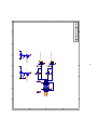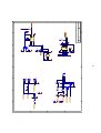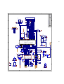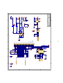
1
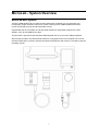
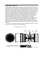
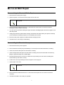
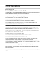
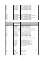
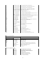
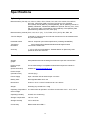
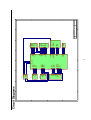
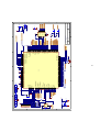
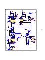
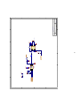
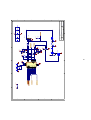
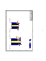
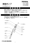
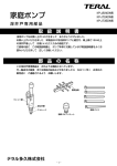
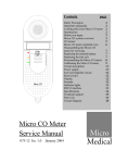
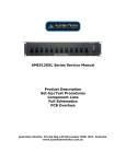
Author
Checked
Approved
Date
Date
Date
MicroLab MK8 Service Manual
085-46 Issue. 1.0
July 2006
1
Contents
MicroLab System overview
MicroLab Mk8 System
Bidirectional Transducer
Page 3
Page 3
Page 4
MicroLab mk8 Repair
Disassembling the MicroLab Mk8 for repairs.
Re-assembling the MicroLab Mk8 after repairs.
Page 5
Page 5
Page 5
Circuit description
Micro Computer Unit:
Overview
Microcontroller
Powers Supply
Microlab8 Sensor Interface
Keypad, EEPROM, MOUSE, RTC, RS232
Printer Driver
Display Driver
Sounder
USB Driver
Memory
085-01
085-02
085-03
085-04
085-05
085-06
085-07
085-08
085-09
085-10
Page 6
Page 6
Page 6
Page 6
Page 6
Page 7
Page 7
Page 7
Page 8
Page 8
Page 8
Page 8
MicroLab Mk8 Parts List
085-00
Page 9
Technical support
Page 18
Fault analysis
Page 18
Specifications
Page 19
Circuit diagrams
Overview
Microcontroller
Powers Supply
Microlab8 Sensor Interface
Keypad, EEPROM, MOUSE, RTC, RS232
Printer Driver
Display Driver
Sounder
USB Driver
Memory
085-01
085-02
085-03
085-04
085-05
085-06
085-07
085-08
085-09
085-10
2
Page 20
Page 21
Page 22
Page 23
Page 24
Page 25
Page 26
Page 27
Page 28
Page 29
MicroLab - System Overview
MicroLab MK8 System
The Micro Medical MicroLab is a data recording spirometer consisting of a microcomputer unit
incorporating a high resolution colour touch screen, Internal printer, USB and RS232 interfaces,
mouse and transducer ports and all associated circuitry.
Supplied with the microcomputer is a Bi-directional transducer, disposable mouthpieces, mains
adapter, nose clip and USB printer cable.
The MicroLab is powered by internal Nickel Metal Hydride cells or by the mains adapter supplied.
When testing a subject, the Bi-directional transducer is plugged into the microcomputer unit. The Bidirectional transducer is used to measure the subjects expired flow and volume in accordance with the
operating manual.
3
Bidirectional Transducer
The Micro Medical digital volume transducer consists of an acrylic tube with a vane
positioned between two swirl plates. The low inertia vane is attached to a stainless
steel pivot that is free to rotate on two jewelled bearings mounted at the centre of the
swirl plates. As air is passed through the transducer a vortex is created by the swirl
plates that causes the vane to rotate in a direction dependant upon the direction of
airflow. The number of rotations is proportional to the volume of air passed through
the transducer and the frequency of rotation is proportional to the flow rate. The
transducer housing consists of a main body that contains a pair of light emitting
diodes (LED’s) and phototransistors. The transducer is fixed to the mouthpiece
holder that pushes into the main body and is captured by an “O” ring seal. The
LED’s produce infrared beams, which are interrupted by the vane twice per
revolution. This interruption is sensed by the phototransistors. The output from the
collector of each phototransistor will be a square wave with a phase difference
between the two of + or - 90 degrees depending upon the direction of flow. The
square waves are detected by a microprocessor that measures the period of each
pulse and transmits that information to the main unit via a high-speed asynchronous
serial link.
There is no routine maintenance required for the transducer other than cleaning
according to the instructions in the operating manual.
Micro Medical Digital Volume Transducer
Rotating
vane
Infra red
emitter
Swirl
plate
Jewelled
bearing
Infra red
detector
Volume = k X No. of pulses
Volume proportional to the number of pulses
Flow proportional to the puse frequency
Flow = k / pulse period
4
MicroLab Mk8 Repair
Disassembling the MicroLab Mk8 for Repairs
1. Disconnect the mains power supply
2. Open the printer cover and remove the paper roll from the unit.
We recommend that you use a Pozidriv No. 1 screwdriver for the following
instruction.
3. Place the MicroLab Mk8 face down on a soft surface to remove the six screws in the lower
moulding. Put the screws to one side.
4. Turn the unit face up before easing the upper and lower mouldings apart. Remove the paper cover
and side panels
5. Taking all precautions against static damage, lift the MicroLab PCB, battery and printer assembly
out of the bottom moulding and place on an antistatic work surface.
6. Reconnect the power supply to the MicroLab Mk8 charging socket
7. The MicroLab is now ready for fault finding.
Reassembling the MicroLab after repairs
1. Disconnect all mains power supplies.
2. Place the MicroLab PCB (and printer/battery if connected) into the MicroLab bottom moulding.
3. Insert the Left hand side panel into the bottom moulding.
4. Insert the Right hand side panel into the bottom moulding and onto the ML8 PCB connectors by
lifting the right hand edge of the PCB slightly
5. Ensuring that the keys do not fall out, position the top moulding over the bottom moulding and
ensure that they both mate correctly.
6. Lift the rear of the top moulding to insert the paper cover hinge pins.
7. clip the paper cover shut
We recommend that you use a Pozidriv No. 1 screwdriver for the following
instruction.
8. Place the MicroLab Mk8 face down on a soft surface and replace the six screws in the lower
moulding.
9. The MicroLab Mk8 is now ready for operation.
5
Circuit Descriptions
Microcomputer Unit
Overview (085-01) and Micro controller (085-02).
The drawing 085-01 is a hierarchical block diagram showing the connections of the sub-sections. The
rest of the drawings are sub-sections and are described in detail below.
U1 is a Sharp LH79520 32 bit microprocessor with 32K of Cache Ram, and no internal flash memory.
The system clock is supplied by 14.7456MHz crystal (X1).
U2 is a reset controller, which holds the reset line low on power up.
J1 is the JTAG interface for programming the unit.
JP1 is the jumper that must be in place for programming, and removed for normal use.
U3 is a multiplexer used to direct the communications to the correct channel on UART1. The
directions are printer, MM Sensor 1, and MM Sensor 2.
Power Supply (085-03)
The power to the system is either supplied by the 8.4V NiMH battery or from an external 12V DC
regulated power supply. If the external supply is connected, then TR6 & TR12 are switched off and
the battery is not used. R8 ensures that the battery is trickle charged at all times.
U40 is the charging circuit for the NiMH battery. The typical charge charge current is about 500mA,
which equates to about 375mA out of the 12V supply.
Charging is disabled when the unit turns on with TR23.
U4 is a step-down switching regulator used to create the 3.3 and 1.8 volt rails.
U6 is a step-down switching regulator used to create the 5V rail.
U43 is a 1Hz oscillator used to blink the LED when the battery is charging. If the battery is fully
charged CHARGE- is high, and the LED is on – assuming the mains is plugged in.
U33 is the power on circuit. If the unit is off and the on/off button is pushed, the unit should turn on.
The microcontroller can turn off the unit using MC_OFF+. Holding the on/off button down for 10 secs
can also turn the unit off if necessary.
U5 is used to hold the unit off if the supply voltage is too low (approximately 5.5V).
R24 and R25 divide the unregulated battery voltage, which is applied to a spare A/D channel in the
touch screen driver. The uC continuously examines the reading and gives a battery low or battery
dead warning message.
Inductors L1 and L2 are placed for EMC filtering and D14 protects the unit from reverse polarity power
supply
6
Microlab8 Sensor Interface (085-04)
2 Sensor ports are available for the unit to plug their transducers into (eg. Turbine, SPO2).
U30 is used to translate the levels from 3.3 to 5V.
U34, and U35, are used to buffer the receive line to the level translator. This was found to be
necessary for the SPO2.
TR17 is used to switch the power on for MM Sensor 1.
TR19 is used to switch the power on for MM Sensor 2.
Keypad, EEPROM, MOUSE, RTC, RS232 (085-05)
Three buttons are available on the unit.
KEY0 is the ON/OFF button.
KEY1 is the HELP button
KEY3 is the PAPER_FEED button
U8 is used to generate an interrupt to the microcontroller if either the on/off or help button is pushed.
The mouse is controlled by 2 data lines. 4 lines come from the microcontroller to interface with these
2 lines. U22, U31 are inverting buffers. TR7 and TR8 are used to drive the data lines low.
BAT2 is a lithium coin cell to give the RTC power for up to 10 years. U10 is the RTC and is clocked by
a 32.768kHz xtal. D2 enables power to be drawn from the main 3.3V regulator when the unit is on.
U25 is a 32Kbyte EEPROM. This is used to store general settings and calibrations.
The uC communicates with the PC an RS232 serial interface at 115,200 Kbits per sec baud rate, with
8 bits data, 1 stop bit and no parity. U9 converts the RS232 signal to a logic signal of 3.3V. The uC
uses channel 0 of it’s inbuilt serial controller for RS232 communication.
Printer Driver (085-06)
The printer driver circuit is controlled by a Hitachi H8/3687 microprocessor. It includes the head driver,
the motor driver, and the paper detection. The microprocessor has a built in Flash, which needs to be
programmed by the main microcontroller, in order for the printer driver to operate correctly.
U12 is used to drive the correct signals to rotate the motor.
U13 is used to translate the communication levels from 3.3 to 5V.
TR1 is to turn off the 5V supply to the printer, when not required.
U7 is a linear regulator for the 7V printer head voltage.
J7 is the connector for the head
J14 is the connector for paper detection
J6 is used for debugging the printer, and should never even be populated in production.
J12 is the connector for the motor.
7
Display Driver (085-07)
The 3.5” TFT LCD Display is driven directly by the main microcontroller. The display has a built in
touch screen and LED backlight, all on the same connector (J8).
U28, and U29 are used to invert 2 lines from the processor.
U14 is the touch screen controller.
U16 controls a constant current through the LED backlight of the display.
U15 can adjust the current to which U16 has to control.
U17 is a step-up switching regulator used to create the appropriate voltages for the display (AVDD
approx 8V, VGH approx 15V, VGL approx –8V).
Sounder (085-08)
The sound driver includes a low-pass filter, a digital potentiometer, and an amplifier. The low-pass
filter (R100, and C110) turn the PWM digital signal from the microcontroller into an analog voltage.
The digital potentiometer (U18) is used to adjust the volume, and the amplifier (U19) is used to drive
the 16ohm speaker with the final signal.
USB Driver (085-09)
The cypress SL811HST (U20) is a host/slave USB controller, which can be used for communicating
with a PC or an external printer.
In host mode 5V power is supplied through TR13, and switched on with TR14.
The chip has is clocked by a 12MHz crystal (X4).
Memory (085-10)
U23 is a 32Mbyte FLASH 28F256P30 used to store all program code, and the files/filing system.
U24 is a 2Mbyte SRAM CY62167DV30 used to store all volatile memory, such as video memory, and
program memory.
8
MicroLab Mk8 Parts List
Parts List For: MicroLab MK8
Drawing No.
085-00
Date 12/12/05
Designation
MIM-085-17 PCB
ASSEMBLY
Part No. (F=Farnell)
Description.
U1
Sharp ARM7 Microcontroller, LQFP176 package
U2
INC-LH79520
INC-LM809M3-3.08
NOPB
U3
INC-MM74HC4052M
Dual 4-ch analog mlplex, SO-16 package, Farnell 3548892
U4
Maxim dual-output step-down converter, QSOP16 package
U5
INC-MAX1775EEE+
INCMAX6457UKD3B+T
U6
INC-MAX1626ESA+
Maxim step-down DC-DC converter, SO-8 package
U8
INC-BU4S11
Rohm individual CMOS NAND gate, SOT23-5 package
U9
INC-MAX3221CAE+
Maxim RS232 transceiver, SSOP16 package
U10
INC-DS1629S+
Maxim digital temp and RTC, SO-8 package, Farnell 3330023
U11
INC-HD64F3687FP
Hitachi microcontroller, FP64E package
U12
INC-L6219DS
Allegro Surface mount PWM Motor driver, SOP24 package
U13
INC-MAX3378EEUD+
Maxim level translator, TSSOP14 package
U14
INC-ADS7846E
Texas Instruments Touch screen controller TSSOP16 package
U15
Maxim digital Potentiometer, SC70 package
U17
INC-MAX5465EXT+
INCLT3465ES6#TRPBF
INCLT1615ES5#TRPBF
U18
INC-MAX5465EXT+
Maxim digital potentiometer, SC70 package
U19
INC-LM4864MM
Audio Power Amplifier, MMSOP package
U20
INC-SL811HST-AXC
Cypress USB controller TQFP48 package
U21
INC-BU4S01
Rohm individual CMOS NOR gate, SOT23-5 package
U22
INC-BU4S584
Rohm individual CMOS Schmitt invertor, SOT23-5 package
U23
Intel NOR Flash, TSOP56_14X20 package
U24
INC-JS28F256P30B85
INC-CY62167DV30LL70ZXI
U25
INC-24LC256I/SN
Microchip 256K EEPROM, SO-8 package
U26
INC-MAX4544EUT+T
Maxim SPDT analogue switch, SOT23-6 package
U27
INC-MAX4544EUT+T
Maxim SPDT analogue switch, SOT23-6 package
U28
INC-BU4S584
Rohm individual CMOS Schmitt invertor, SOT23-5 package
U29
INC-BU4S584
Rohm individual CMOS Schmitt invertor, SOT23-5 package
U30
INC-MAX3378EEUD+
Maxim level translator, TSSOP14 package
U31
INC-BU4S584
Rohm individual CMOS Schmitt invertor, SOT23-5 package
U33
INC-4093
CMOS Quad NAND Schmitt input gate, SO-14 package
U34
INC-BU4S81
Rohm individual CMOS AND gate, SOT23-5 package
U35
Rohm individual CMOS AND gate, SOT23-5 package
U40
INC-BU4S81
INCLTC4010CFE#TRPBF
U42
INC-LT1084CT#TRPBF
U42 PAD
PAD-OE02910
Linear Technology Voltage Regulator
CPC Sellotape permanent, double-sided, self adhesive pad
12x25x1.5mm
U43
INC-LM555CM
National Semiconductor 555 Timer IC, SO-8
TR1
TRA-DTC114EK
High speed switching NPN transistor, size SOT23
TR2
TRA-FDN360P
Fairchild Semiconductor P-channel Mosfet, size SOT-23
TR3
TRA-FDN361AN
Fairchild Semiconducter N-channel Mosfet, size SOT-23
TR4
TRA-FDN360P
Fairchild Semiconductor P-channel Mosfet, size SOT-23
TR5
TRA-DTC114EK
High speed switching NPN transistor, size SOT23
Revision No. 1.2
U16
Page: 1 OF 7
National Semiconductor Reset Circuit, SOT-23 package
Maxim undervoltage sensing circuit, SOT23-5 package
Linear Technology White LED Driver, SOT-23 package
Linear Technology DC/DC convertor, SOT23-5 package
Cypress 256Mbit SRAM, TSOP48_12X20 package
Linear Technology Battery Charging Circuit, TSSOP16 package
9
TR6
TRA-DTC114EK
High speed switching NPN transistor, size SOT23
TR7
TRA-DTC114EK
High speed switching NPN transistor, size SOT23
TR8
TRA-DTC114EK
High speed switching NPN transistor, size SOT23
TR9
TRA-FMMT491A
Zetex NPN transistor, size SOT-23
TR10
TRA-DTA114EK
High speed switching PNP transistor, size SOT23
TR11
TRA-FDN360P
Fairchild Semiconductor P-channel Mosfet, size SOT-23
TR12
TRA-FDN360P
Fairchild Semiconductor P-channel Mosfet, size SOT-23
TR13
TRA-FDN360P
Fairchild Semiconductor P-channel Mosfet, size SOT-23
TR14
TRA-DTC114EK
High speed switching NPN transistor, size SOT23
TR15
TRA-DTC114EK
High speed switching NPN transistor, size SOT23
TR16
TRA-FDN360P
Fairchild Semiconductor P-channel Mosfet, size SOT-23
TR17
TRA-DTC114EK
High speed switching NPN transistor, size SOT23
TR18
TRA-FDN360P
Fairchild Semiconductor P-channel Mosfet, size SOT-23
TR19
TRA-DTC114EK
High speed switching NPN transistor, size SOT23
TR20
TRA-FMMT491A
Zetex NPN transistor, size SOT-23
TR21
TRA-FDN360P
Fairchild Semiconductor P-channel Mosfet, size SOT-23
TR22
TRA-FDN361AN
Fairchild Semiconducter N-channel Mosfet, size SOT-23
R1
RES-5.6K0603
5.6K Surface mount resistor 0.063 watt 1% size 0603
R2
RES-75R0603
75R Surface mount resistor 0.063 watt 1% size 0603
R3
RES-10K0603
10K Surface mount resistor 0.063 watt 1% size 0603
Parts List For: MicroLab MK8
Drawing No.
085-00
Date 12/12/05
Designation
Part No. (F=Farnell)
Description.
R4
RES-10K0603
10K Surface mount resistor 0.063 watt 1% size 0603
R5
RES-10K0603
10K Surface mount resistor 0.063 watt 1% size 0603
R6
RES-10K0603
10K Surface mount resistor 0.063 watt 1% size 0603
R7
RES-10K0603
10K Surface mount resistor 0.063 watt 1% size 0603
R8
RES-1K0805
1K Surface mount resistor 0.125 watt 1% size 0805
R9
RES-1M0603
1M Surface mount resistor 0.063 watt 1% size 0603
R10
RES-100K0603
100K Surface mount resistor 0.063 watt 1% size 0603
R11
RES-100K0603
100K Surface mount resistor 0.063 watt 1% size 0603
R12
RES-100R0603
100R Surface mount resistor 0.063 watt 1% size 0603
R13
RES-100K0603
100K Surface mount resistor 0.063 watt 1% size 0603
R14
RES-22K0603
22K Surface mount resistor 0.063 watt 1% size 0603
R15
RES-1M0603
1M Surface mount resistor 0.063 watt 1% size 0603
R16
RES-432K0603
432K Surface mount resistor 0.063 watt 1% size 0603
R17
RES-100K0603
100K Surface mount resistor 0.063 watt 1% size 0603
R18
RES-36K0603
36K Surface mount resistor 0.063 watt 1% size 0603
R19
RES-22K0603
22K Surface mount resistor 0.063 watt 1% size 0603
R20
RES-22K0603
22K Surface mount resistor 0.063 watt 1% size 0603
R21
RES-27K0603
27K Surface mount resistor 0.063 watt 1% size 0603
R22
RES-0.1R0805
0.1R Surface mount resistor 0.25 watt 1% size 0805
R23
RES-0.047R0805
0.047R Surface mount resistor 0.25 watt 1% size 0805
R24
RES-100K0603
100K Surface mount resistor 0.063 watt 1% size 0603
R25
RES-47K0603
47K Surface mount resistor 0.063 watt 1% size 0603
R26
RES-100K0603
100K Surface mount resistor 0.063 watt 1% size 0603
R27
RES-0.1R0805
0.1R Surface mount resistor 0.25 watt 1% size 0805
R28
RES-1K0603
1K Surface mount resistor 0.063 watt 1% size 0603
R29
RES-0.1R0805
0.1R Surface mount resistor 0.25 watt 1% size 0805
R30
RES-10K0603
10K Surface mount resistor 0.063 watt 1% size 0603
Revision No. 1.2
Page: 2 OF 7
10
R31
RES-100K0603
100K Surface mount resistor 0.063 watt 1% size 0603
R32
RES-100K0603
100K Surface mount resistor 0.063 watt 1% size 0603
R33
RES-100K0603
100K Surface mount resistor 0.063 watt 1% size 0603
R34
RES-100R0603
100R Surface mount resistor 0.063 watt 1% size 0603
R35
RES-0.1R0805
0.1R Surface mount resistor 0.25 watt 1% size 0805
R36
RES-10M0805
10M Surface mount resistor 0.125 watt 1% size 0805
R37
RES-100K0603
100K Surface mount resistor 0.063 watt 1% size 0603
R38
RES-10K0603
10K Surface mount resistor 0.063 watt 1% size 0603
R39
RES-0.1R0805
0.1R Surface mount resistor 0.25 watt 1% size 0805
R40
RES-10K0603
10K Surface mount resistor 0.063 watt 1% size 0603
R41
RES-10K0603
10K Surface mount resistor 0.063 watt 1% size 0603
R42
RES-10K0603
10K Surface mount resistor 0.063 watt 1% size 0603
R43
RES-10K0603
10K Surface mount resistor 0.063 watt 1% size 0603
R44
RES-100K0603
100K Surface mount resistor 0.063 watt 1% size 0603
R45
RES-10K0603
10K Surface mount resistor 0.063 watt 1% size 0603
R46
RES-100K0603
100K Surface mount resistor 0.063 watt 1% size 0603
R47
RES-10K0603
10K Surface mount resistor 0.063 watt 1% size 0603
R48
RES-1R0603
1R Surface mount resistor 0.063 watt 1% size 0603
R49
RES-1K0603
1K Surface mount resistor 0.063 watt 1% size 0603
R50
RES-1R0603
1R Surface mount resistor 0.063 watt 1% size 0603
R51
RES-1K0603
1K Surface mount resistor 0.063 watt 1% size 0603
R52
RES-33K0603
33K Surface mount resistor 0.063 watt 1% size 0603
R53
RES-33K0603
33K Surface mount resistor 0.063 watt 1% size 0603
R54
RES-100K0603
100K Surface mount resistor 0.063 watt 1% size 0603
R55
RES-100K0603
100K Surface mount resistor 0.063 watt 1% size 0603
R56
RES-100K0603
100K Surface mount resistor 0.063 watt 1% size 0603
R57
RES-100K0603
100K Surface mount resistor 0.063 watt 1% size 0603
R58
RES-100K0603
100K Surface mount resistor 0.063 watt 1% size 0603
R59
RES-100K0603
100K Surface mount resistor 0.063 watt 1% size 0603
R60
RES-22K0603
22K Surface mount resistor 0.063 watt 1% size 0603
R61
RES-22K0603
22K Surface mount resistor 0.063 watt 1% size 0603
R62
RES-22K0603
22K Surface mount resistor 0.063 watt 1% size 0603
Parts List For: MicroLab MK8
Drawing No.
085-00
Date 12/12/05
Designation
Part No. (F=Farnell)
Description.
R63
RES-100K0603
100K Surface mount resistor 0.063 watt 1% size 0603
R64
RES-100K0603
100K Surface mount resistor 0.063 watt 1% size 0603
R65
RES-0.1R0805
0.1R Surface mount resistor 0.25 watt 1% size 0805
R66
RES-100K0603
100K Surface mount resistor 0.063 watt 1% size 0603
R67
RES-100K0603
100K Surface mount resistor 0.063 watt 1% size 0603
R68
RES-100K0603
100K Surface mount resistor 0.063 watt 1% size 0603
R69
RES-100K0603
100K Surface mount resistor 0.063 watt 1% size 0603
R70
RES-100K0603
100K Surface mount resistor 0.063 watt 1% size 0603
R72
RES-8.2R0805
8.2R Surface mount resistor 0.125 watt 1% size 0805
R73
RES-91K0603
91K Surface mount resistor 0.063 watt 1% size 0603
R74
RES-15K0603
15K Surface mount resistor 0.063 watt 1% size 0603
R75
RES-51K0603
51K Surface mount resistor 0.063 watt 1% size 0603
R76
RES-1K0603
1K Surface mount resistor 0.063 watt 1% size 0603
R77
RES-47K0603
47K Surface mount resistor 0.063 watt 1% size 0603
R78
RES-7.5K0603
7.5K Surface mount resistor 0.063 watt 1% size 0603
R79
RES-5.6K0603
5.6K Surface mount resistor 0.063 watt 1% size 0603
R80
RES-100K0603
100K Surface mount resistor 0.063 watt 1% size 0603
Revision No. 1.2
Page: 3 OF 7
11
R81
RES-100K0603
100K Surface mount resistor 0.063 watt 1% size 0603
R82
RES-10K0603
10K Surface mount resistor 0.063 watt 1% size 0603
R83
RES-10K0603
10K Surface mount resistor 0.063 watt 1% size 0603
R84
RES-1M0603
1M Surface mount resistor 0.063 watt 1% size 0603
R85
RES-100K0603
100K Surface mount resistor 0.063 watt 1% size 0603
R86
RES-100K0603
100K Surface mount resistor 0.063 watt 1% size 0603
R87
RES-1.5K0603
1.5K Surface mount resistor 0.063 watt 1% size 0603
R88
RES-33R0603
33R Surface mount resistor 0.063 watt 1% size 0603
R89
RES-33R0603
33R Surface mount resistor 0.063 watt 1% size 0603
R90
RES-15K0603
15K Surface mount resistor 0.063 watt 1% size 0603
R91
RES-15K0603
15K Surface mount resistor 0.063 watt 1% size 0603
R92
RES-100K0603
100K Surface mount resistor 0.063 watt 1% size 0603
R93
RES-0.1R0805
0.1R Surface mount resistor 0.25 watt 1% size 0805
R94
RES-100K0603
100K Surface mount resistor 0.063 watt 1% size 0603
R95
RES-10K0603
10K Surface mount resistor 0.063 watt 1% size 0603
R96
RES-10K0603
10K Surface mount resistor 0.063 watt 1% size 0603
R97
RES-0.1R0805
0.1R Surface mount resistor 0.25 watt 1% size 0805
R98
RES-0.1R0805
0.1R Surface mount resistor 0.25 watt 1% size 0805
R99
RES-0.1R0805
0.1R Surface mount resistor 0.25 watt 1% size 0805
R100
RES-3.3K0603
3.3K Surface mount resistor 0.063 watt 1% size 0603
R101
RES-1M0603
1M Surface mount resistor 0.063 watt 1% size 0603
R102
RES-18K0805
18K Surface mount resistor 0.125 watt 1% size 0805
R103
RES-100K0805
100K Surface mount resistor 0.125 watt 1% size 0805
R104
RES-100K0603
100K Surface mount resistor 0.063 watt 1% size 0603
R105
RES-0.22R0805
0.22R Surface mount resistor 0.25 watt 1% size 0805
R106
RES-604K0603
604K Surface mount resistor 0.063 watt 1% size 0603
R107
RES-100K0603
100K Surface mount resistor 0.063 watt 1% size 0603
R108
RES-100K0603
100K Surface mount resistor 0.063 watt 1% size 0603
R109
RES-121R0603
121R Surface mount resistor 0.063 watt 1% size 0603
R110
RES-560R0805
560R Surface mount resistor 0.125 watt 1% size 0805
R111
RES-100K0603
100K Surface mount resistor 0.063 watt 1% size 0603
R112
RES-100K0603
100K Surface mount resistor 0.063 watt 1% size 0603
R113
RES-100K0603
100K Surface mount resistor 0.063 watt 1% size 0603
R114
RES-100K0603
100K Surface mount resistor 0.063 watt 1% size 0603
R116
RES-0.1R0805
0.1R Surface mount resistor 0.25 watt 1% size 0805
R117
RES-100K0603
100K Surface mount resistor 0.063 watt 1% size 0603
R119
RES-0.1R0805
0.1R Surface mount resistor 0.25 watt 1% size 0805
R120
RES-100K0603
100K Surface mount resistor 0.063 watt 1% size 0603
R121
RES-100K0603
100K Surface mount resistor 0.063 watt 1% size 0603
R122
RES-100K0603
100K Surface mount resistor 0.063 watt 1% size 0603
R123
RES-100K0603
100K Surface mount resistor 0.063 watt 1% size 0603
R124
RES-100K0603
100K Surface mount resistor 0.063 watt 1% size 0603
R125
RES-100K0603
100K Surface mount resistor 0.063 watt 1% size 0603
R126
RES-100K0603
100K Surface mount resistor 0.063 watt 1% size 0603
R127
RES-22K0603
22K Surface mount resistor 0.063 watt 1% size 0603
Parts List For: MicroLab MK8
Drawing No.
085-00
Revision No. 1.2
Date 12/12/05
Page: 4 OF 7
Designation
Part No. (F=Farnell)
Description.
R128
RES-68K0603
68K Surface mount resistor 0.063 watt 1% size 0603
R129
RES-33K0603
33K Surface mount resistor 0.063 watt 1% size 0603
12
R130
RES-330R0805
330R Surface mount resistor 0.063 watt 1% size 0805
R131
RES-100K0603
100K Surface mount resistor 0.063 watt 1% size 0603
R132
RES-100K0603
100K Surface mount resistor 0.063 watt 1% size 0603
R133
RES-100K0603
100K Surface mount resistor 0.063 watt 1% size 0603
R134
RES-100K0603
100K Surface mount resistor 0.063 watt 1% size 0603
R135
RES-100K0603
100K Surface mount resistor 0.063 watt 1% size 0603
R136
RES-100K0603
100K Surface mount resistor 0.063 watt 1% size 0603
R137
RES-0.1R0805
0.1R Surface mount resistor 0.25 watt 1% size 0805
R138
RES-33K0603
33K Surface mount resistor 0.063 watt 1% size 0603
R139
RES-10K0603
10K Surface mount resistor 0.063 watt 1% size 0603
R140
RES-100K0603
100K Surface mount resistor 0.063 watt 1% size 0603
R141
RES-100K0603
100K Surface mount resistor 0.063 watt 1% size 0603
R142
RES-100K0603
100K Surface mount resistor 0.063 watt 1% size 0603
R143
RES-100K0603
100K Surface mount resistor 0.063 watt 1% size 0603
R145
RES-100K0603
100K Surface mount resistor 0.063 watt 1% size 0603
C1
CAP-0.1UF0603
0.1uF 25V ceramic capacitor size 0603
C2
CAP-0.1UF0603
0.1uF 25V ceramic capacitor size 0603
C3
CAP-0.1UF0603
0.1uF 25V ceramic capacitor size 0603
C4
CAP-0.1UF0603
0.1uF 25V ceramic capacitor size 0603
C5
CAP-0.1UF0603
0.1uF 25V ceramic capacitor size 0603
C6
CAP-0.1UF0603
0.1uF 25V ceramic capacitor size 0603
C7
CAP-0.1UF0603
0.1uF 25V ceramic capacitor size 0603
C8
CAP-0.1UF0603
0.1uF 25V ceramic capacitor size 0603
C9
CAP-0.1UF0603
0.1uF 25V ceramic capacitor size 0603
C10
CAP-0.1UF0603
0.1uF 25V ceramic capacitor size 0603
C11
CAP-10PF0603
10pF ceramic capacitor size 0603
C12
CAP-10PF0603
10pF ceramic capacitor size 0603
C13
don't populate
C14
don't populate
C15
CAP-TPSC336K16R0300
AVX 33uF/16v surface mount Tantalum. Farnell 301-8544
C16
CAP-10UF1206
10uF 10V ceramic capacitor size 1206
C17
CAP-10UF1206
10uF 10V ceramic capacitor size 1206
C18
CAP-0.1UF0603
0.1uF 25V ceramic capacitor size 0603
C19
CAP-0.1UF0603
0.1uF 25V ceramic capacitor size 0603
C20
CAP-10NF0603
10nF ceramic capacitor size 0603
C21
CAP-1UF0805
1uF 25V ceramic capacitor size 0805
C22
CAP-TPSC336K16R0300
AVX 33uF/16v surface mount Tantalum. Farnell 301-8544
C23
CAP-1UF0805
1uF 25V ceramic capacitor size 0805
C24
CAP-0.22UF0805
0.22uF 25V ceramic capacitor size 0805
C25
CAP-2.2UF0805
2.2uF 25V ceramic capacitor size 0805
C26
CAP-0.1UF0805
0.1uF 25V ceramic capacitor size 0805
C27
CAP-0.47UF0805
0.47uF 25V ceramic capacitor size 0805
C28
CAP-2.2UF0805
2.2uF 25V ceramic capacitor size 0805
C29
CAP-1UF0805
1uF 25V ceramic capacitor size 0805
C30
CAP-TPSC336K16R0300
AVX 33uF/16v surface mount Tantalum. Farnell 301-8544
C31
CAP-0.1UF0603
0.1uF 25V ceramic capacitor size 0603
C32
CAP-0.1UF0603
0.1uF 25V ceramic capacitor size 0603
C33
CAP-0.1UF0603
0.1uF 25V ceramic capacitor size 0603
C34
CAP-0.1UF0603
0.1uF 25V ceramic capacitor size 0603
C35
CAP-0.1UF0603
0.1uF 25V ceramic capacitor size 0603
C36
CAP-0.1UF0603
0.1uF 25V ceramic capacitor size 0603
C37
CAP-0.1UF0603
0.1uF 25V ceramic capacitor size 0603
C38
CAP-TAJD107K016R
AVX 100uF/16v Surface mount Tantalum. Farnell 197-348
C39
CAP-0.1UF0603
0.1uF 25V ceramic capacitor size 0603
13
C40
CAP-0.1UF0603
0.1uF 25V ceramic capacitor size 0603
C41
CAP-0.1UF0603
0.1uF 25V ceramic capacitor size 0603
C43
CAP-TAJD107K016R
AVX 100uF/16v Surface mount Tantalum. Farnell 197-348
C44
CAP-820PF0603
820pF ceramic capacitor size 0603
Parts List For: MicroLab MK8
Drawing No.
085-00
Date 12/12/05
Designation
Part No. (F=Farnell)
Description.
C45
CAP-820PF0603
820pF ceramic capacitor size 0603
C46
CAP-820PF0603
820pF ceramic capacitor size 0603
C47
CAP-820PF0603
820pF ceramic capacitor size 0603
C48
CAP-10NF0603
10nF ceramic capacitor size 0603
C49
CAP-0.1UF0603
0.1uF 25V ceramic capacitor size 0603
C50
CAP-33PF0603
33pF ceramic capacitor size 0603
C51
CAP-33PF0603
33pF ceramic capacitor size 0603
C52
CAP-0.1UF0603
0.1uF 25V ceramic capacitor size 0603
C53
CAP-0.1UF0603
0.1uF 25V ceramic capacitor size 0603
C54
CAP-0.1UF0603
0.1uF 25V ceramic capacitor size 0603
C55
CAP-0.1UF0603
0.1uF 25V ceramic capacitor size 0603
C56
CAP-0.1UF0603
0.1uF 25V ceramic capacitor size 0603
C57
CAP-0.1UF0603
0.1uF 25V ceramic capacitor size 0603
C58
CAP-0.1UF0603
0.1uF 25V ceramic capacitor size 0603
C59
CAP-0.1UF0603
0.1uF 25V ceramic capacitor size 0603
C60
CAP-0.1UF0603
0.1uF 25V ceramic capacitor size 0603
C61
CAP-10NF0603
10nF ceramic capacitor size 0603
C62
CAP-10NF0603
10nF ceramic capacitor size 0603
C63
CAP-10NF0603
10nF ceramic capacitor size 0603
C64
CAP-10NF0603
10nF ceramic capacitor size 0603
C66
CAP-1UF0805
1uF 25V ceramic capacitor size 0805
C67
CAP-2.2UF0805
2.2uF 25V ceramic capacitor size 0805
C68
CAP-0.1UF0603
0.1uF 25V ceramic capacitor size 0603
C69
CAP-TPSC336K16R0300
AVX 33uF/16v surface mount Tantalum. Farnell 301-8544
Revision No. 1.2
Page: 5 OF 7
C70
CAP-TPSC336K16R0300
AVX 33uF/16v surface mount Tantalum. Farnell 301-8544
C71
CAP-1UF0805
1uF 25V ceramic capacitor size 0805
C72
CAP-0.1UF0603
0.1uF 25V ceramic capacitor size 0603
C73
CAP-TPSC336K16R0300
AVX 33uF/16v surface mount Tantalum. Farnell 301-8544
C74
CAP-0.1UF0603
0.1uF 25V ceramic capacitor size 0603
C75
CAP-TPSC336K16R0300
AVX 33uF/16v surface mount Tantalum. Farnell 301-8544
C76
CAP-2.2UF0805
2.2uF 25V ceramic capacitor size 0805
C77
CAP-0.1UF0603
0.1uF 25V ceramic capacitor size 0603
C78
CAP-0.1UF0603
0.1uF 25V ceramic capacitor size 0603
C79
CAP-0.1UF0603
0.1uF 25V ceramic capacitor size 0603
C80
CAP-1UF0805
1uF 25V ceramic capacitor size 0805
C81
CAP-1UF0805
1uF 25V ceramic capacitor size 0805
C83
CAP-22PF0603
22pF ceramic capacitor size 0603
C84
CAP-22PF0603
22pF ceramic capacitor size 0603
C85
CAP-0.1UF0805
0.1uF 25V ceramic capacitor size 0805
C86
CAP-2.2UF0805
2.2uF 25V ceramic capacitor size 0805
C87
CAP-0.1UF0603
0.1uF 25V ceramic capacitor size 0603
C88
CAP-0.1UF0603
0.1uF 25V ceramic capacitor size 0603
C89
CAP-0.1UF0603
0.1uF 25V ceramic capacitor size 0603
C90
CAP-0.1UF0603
0.1uF 25V ceramic capacitor size 0603
C91
CAP-0.1UF0603
0.1uF 25V ceramic capacitor size 0603
14
C92
CAP-0.1UF0603
0.1uF 25V ceramic capacitor size 0603
C93
CAP-0.1UF0603
0.1uF 25V ceramic capacitor size 0603
C94
CAP-0.1UF0603
0.1uF 25V ceramic capacitor size 0603
C95
CAP-0.1UF0603
0.1uF 25V ceramic capacitor size 0603
C96
CAP-0.1UF0603
0.1uF 25V ceramic capacitor size 0603
C97
CAP-1UF0805
1uF 25V ceramic capacitor size 0805
C98
CAP-0.1UF0805
0.1uF 25V ceramic capacitor size 0805
C99
CAP-EEVFK1C470UR
Panasonic 47uF electrolytic UWX5 package. Farnell 383-5856
C100
CAP-0.1UF0603
0.1uF 25V ceramic capacitor size 0603
C101
CAP-TAJD107K016R
AVX 100uF/16v Surface mount Tantalum. Farnell 197-348
C102
CAP-0.1UF0603
0.1uF 25V ceramic capacitor size 0603
C103
CAP-TPSC336K16R0300
AVX 33uF/16v surface mount Tantalum. Farnell 301-8544
C104
CAP-0.1UF0603
0.1uF 25V ceramic capacitor size 0603
C105
CAP-TPSC336K16R0300
AVX 33uF/16v surface mount Tantalum. Farnell 301-8544
C106
CAP-0.1UF0603
0.1uF 25V ceramic capacitor size 0603
C107
CAP-0.1UF0603
0.1uF 25V ceramic capacitor size 0603
Parts List For: MicroLab MK8
Drawing No.
085-00
Date 12/12/05
Designation
Part No. (F=Farnell)
Description.
C108
CAP-0.1UF0603
0.1uF 25V ceramic capacitor size 0603
C109
CAP-1UF0805
1uF 25V ceramic capacitor size 0805
C110
CAP-10NF0603
10nF ceramic capacitor size 0603
C111
CAP-1UF0805
1uF 25V ceramic capacitor size 0805
C113
CAP-TPSC336K16R0300
AVX 33uF/16v surface mount Tantalum. Farnell 301-8544
C114
CAP-TPSC336K16R0300
AVX 33uF/16v surface mount Tantalum. Farnell 301-8544
Revision No. 1.2
Page: 6 OF 7
C115
CAP-TPSC336K16R0300
AVX 33uF/16v surface mount Tantalum. Farnell 301-8544
C117
CAP-10UF1206
10uF 10V ceramic capacitor size 1206
C118
CAP-1UF0603
1uF 25V ceramic capacitor size 0805
C120
CAP-10NF0603
10nF ceramic capacitor size 0603
C121
CAP-0.1UF0603
0.1uF 25V ceramic capacitor size 0603
C122
CAP-0.1UF0603
0.1uF 25V ceramic capacitor size 0603
C123
CAP-0.1UF0805
0.1uF 25V ceramic capacitor size 0805
C130
CAP-0.1UF0603
0.1uF 25V ceramic capacitor size 0603
D1
DIO-BAT54C
General purpose Dual Schottky diode, Common Cathode
D2
DIO-BAT54C
General purpose Dual Schottky diode, Common Cathode
D3
DIO-ZHCS1000
Zetex Schottky diode, SOT-23 package
D4
DIO-ZHCS1000
Zetex Schottky diode, SOT-23 package
D5
LED-L-934ND
Kingbright 3mm orange LED. Farnell 329-9478
D6
DIO-ZHCS1000
Zetex Schottky diode, SOT-23 package
D7
DIO-BAT54S
General purpose Dual Schottky diode in Series
D8
DIO-BAT54S
General purpose Dual Schottky diode in Series
D9
DIO-BAS21
General purpose diode
D10
DIO-BAS21
General purpose diode
D11
DIO-ZHCS1000
Zetex Schottky diode, SOT-23 package
D13
DIO-ZHCS1000
Zetex Schottky diode, SOT-23 package
D14
DIO-SMAJ12A
General Semiconductor TVS 12V protection diode, DO214 package
D15
DIO-BAS21
General purpose diode
D16
DIO-BAS21
General purpose diode
D17
DIO-BAS21
IND-NLC565050T3R9K-PF
IND-NLC565050T3R9K-PF
General purpose diode
L1
L2
TDK 3.9uH inductor
TDK 3.9uH inductor
15
L3
IND-B82462-G4103-M
Epcos 10uH Power Inductor, Farnell 7430027
L4
IND-LQH32CN100K33L
muRate 10uH inductor, 1210 package, Farnell 9522204
L5
IND-B82462-G4223-M
Epcos 22uH Power Inductor, Farnell 7430043
L6
IND-LQH32MN220J23L
muRate 22uH inductor, 1210 package, Farnell 9522069
L7
IND-LQH32CN100K33L
muRate 10uH inductor, 1210 package, Farnell 9522204
L8
IND-BLM41PG750SN1B
muRata inductor, 1806 package.
L9
IND-DO3340P-103ML
Coilcraft 10uH inductor
X1
XTL-14.745HC49/4H
14.745 MHz crystal, HC49/4H package
X2
XTL-32.768WATCH
Seiko C-001R 32.768 KHz crystal, WATCH package. Farnell 571672
X3
14.745 MHz crystal, HC49/4H package
X4
XTL-14.745HC49/4H
XTLCS1012.000MABJTR
Citizen 12MHz surface mount crystal. Digi-Key 300-8089-1-ND
F1
FUS-MINISMD050-2
Tyco 0.5A surface mount Polyswitch. RS 136-864
F2
FUS-MF-SM150-2
Bourns Surface Mount 3 Amp Resettable Fuse
BAT1
SKT-B2B-PH-K-S
JST 2 way PCB socket
BAT2
BAT-CR2430PCB
Varta 260mA-hr PCB mounted coin cell battery. Farnell 425345
J1
CON-M20-9980706
Harwin 7x2-way 2.54mm pitch Header
J2
CON-CN06486
CPC DC Power Socket
J3
CON-MQ172X-4PA(55)
Hirose 4-way connector
J4
CON-MQ172X-4PA(55)
Hirose 4-way connector
J5
CON-MJ2135
3.5mm 4-pole Jack Socket (Farnell 5096297)
J6
Not Used
Printer Debug Port
J7
Hirose 22way connector
J8
CON-FH12-22S-1SV(55)
CON-FH12-50S0.5SV(55)
J9
SPK-KDM-40016
Roxborough speaker
J10
CON-56579-0588
Molex USB Mini AB connector
J12
CON-52852-0470
Molex 4-way 1mm pitch FFC connector
J13
CON-RP34L5R-3PD(71)
Hirose 3-way connector
J14
CON-52852-0470
Molex 4-way 1mm pitch FFC connector
JP1
CON-M20-9990206
Harwin 2-way 2.54mm pitch Header (Farnell 511705)
Hirose 50way connector
Parts List For: MicroLab MK8
Drawing No.
085-00
Date 12/12/05
Designation
Part No. (F=Farnell)
Description.
KEY0
SWT-TSS644R
Knitter-switch switch
KEY1
SWT-TSS644R
Knitter-switch switch
KEY3
SWT-TSS644R
Knitterswitch switch
VR1
POT-3150W203P
Tyco Electronics 20K surface mount pot. Farnell 4631869
Revision No. 1.2
Page: 7 OF 7
HEAT6900
Aavid Thermalloy heatsink TO220 type PF433 for U42.
TX09D70Vm1CAA
Hitachi 1/4 VGA colour TFT display
MIM-085-27
MicroLab - display holder
MIM-085-11
PCB issue 1.0
MIM-039-18 TURBINE ASSEMBLY
MIM-031-17
2 off moulded turbine inner swirl plate
MIM-031-18
2 off moulded turbine outer swirl plate
MIM-039-12
Transducer Body - Reduced Cone Diameter
MIM-039-02
Mouthpiece holder
MIM-039-14
Jewelled fixed bearing M3 thread
MIM-039-16
Jewelled sprung bearing M3 thread
MIM-039-17
27mm offset vane assembly
16
MIM-039-15
27mm Pivot
MIM-039-08
Flow deflector plate (039-08 iss 1.3)
BI-DIRECTIONAL TURBINE HOUSING MIM-101-00
CASE COMPONENTS
MIM-085-18
MicroLab - top moulding
MIM-085-19
MicroLab - bottom moulding
MIM-085-20
MicroLab - paper cover
MIM-085-21
MicroLab - display bezel
MIM-085-22
MicroLab - right hand panel
MIM-085-23
MicroLab - left hand panel
MIM-085-24
2 off MicroLab - front feet
MIM-085-25
2 off MicroLab - rear feet
MIM-085-26
MicroLab - hinged foot
MIM-085-28
MicroLab - paper feed key
MIM-085-29
MicroLab - on/off key
MIM-085-30
MicroLab - help key
MIM-085-16
Serial Number label
MIM-085-15
8.4 Volt 1.1A-hr NiMH battery pack
MEC-Porti-M400
SCWW/3.0/8/PRST30/ZC1D
Woosim thermal printer mechanism
6 off TR fastenings, polymate 30 panhead screw, posidrive,
3x8mm zinc & clear finish
Alt. Part
SCW202101412KB30086
6 off Harrison Silverdale, polypast 30 screw, panhead, posidrive
3x8mm zinc & clear finish
MIM-085-35 MOUSE ASSEMBLY
SWT-13083
Mini optical USB/PS2 mouse available from PWM
PLG-509-6212
Farnell 4 pole 3.5mm jack plug
PSUMW128RA1200F02
Ault universal 15 volt mains adapter supplied by Craftec
SUNDRY ITEMS
USB lead
Three pole mains cable for destination country
17
Technical Support
Great Britain and World Headquarters
Micro Medical Ltd
PO Box 6
Rochester
Kent ME1 2AZ
Telephone + 44 (0)1634 360044
Fax
+44 (0)1634 360055
Web Site http://www.micromedical.com.uk
Email
[email protected]
Contact Micro Medical Ltd for the local agent in your region or country for local service:
Fault Analysis
The following analysis is only a guideline and should be carried out in a logical sequence. If the fault is
still apparent after the following suggestions then the unit should be fault found using the circuit
descriptions and circuit diagrams provided.
When the unit is turned on there is no display present
-Ensure charger is turned on at the mains.
FVC readings are low
-Remove turbine from transducer housing. Taking the turbine, move it slowly through the air and
check that the vane is not sticking.
The unit does not recognise that the transducer is connected
-Ensure that the Bi-directional transducer is correctly plugged into the MicroLab.
-Inspect the Bi-directional transducer cable and connector for damage.
The unit does not record any blows
-Inspect Bi-directional transducer cable and connector for damage.
-Ensure that the Bi-directional transducer is correctly plugged into the MicroLab.
-Remove turbine from the Bi-directional transducer housing. Taking the turbine, move it slowly
through the air and check that the vane is not sticking.
18
Specifications
Spirometry
Measurements, (Forced) VC, FEV.75, FEV1, FEV3, FEV6, FVC, PEF, FEV.75/VC, FEV.75/FVC,
FEV1/VC, FEV1/FVC (FER), FEV3/VC, FEV3/FVC, FEV.75/FEV6,
FEV1/FEV6, FEF25 (MEF75), FEF50 (MEF50), FEF75 (MEF25), FEF25-75
(MMEF), FEF50/VC, FEF50/FVC, MMEF/FVC (FEF25-75/FVC), FIV1, FIVC,
PIF, FIV1/FIVC (FIR), FIF25 (MIF75), FIF50 (MIF50), FIF75 (MIF25), R50
(FEF50/FIF50), MET25-75, FET, MVV (ind)
Measurements, (relaxed) EVC, IVC, IC,VT (TV), ,Ti,Te,Ti/Ttot.,VT/Ti (TV/Ti), IRV, ERV, FR
Test Per Subject
5 relaxed VC manoeuvres and 8 forced manoeuvres for each baseline and
two post examinations
Predicted Values
Various - depends upon national preference (including NHANESIII)
Transducer
Resolution
Micro Medical Gold Standard Bi-Directional Digital Volume
10ml volume 0.03l/s flow
Accuracy
+/- 3% to ATS recommendations - Standardisation of Spirometry 1994
update for flows and volumes
General
Storage
graphs
2000 patients with tests including Flow/Volume loops and Volume/Time
Printer Output
Medical
(External Printers)
For the latest listing of compatible Hewlett Packard printers visit Micro
Website at www.micromedical.co.uk
Printer Output
(internal Printer)
13mm/s (avg)
Power Supply
Input: 100-240V AC 50-60Hz Output: 12V 2.5A
Battery Pack
Rechargeable NiMH 8.4V 1Ah
Dimensions
25.5cm x 12cm x 3.5cm Transducer 50 x 60 x 90mm
Weight
Excluding any transducers : 630g
Operating Temperature The instrument will operate in a uniform environment of 0°C - 40°C, out of
direct sunlight
Operating Humidity
30-90% non-condensing.
Storage Temperature
-20°C to +70°C
Storage humidity
10% to 90% RH
Connectivity
RS232 serial and USB 1.1
19
A
B
C
D
1
1
Circuit Diagrams
2
2
PRNBUSY
PRN_RST+
PRNONLINE
PRINTDATA
PRINTACK
PRN_PRG-
MM1_PWR+
MM1_Tx
MM1_Rx
MM2_PWR+
MM2_Tx
MM2_Rx
FastCharge-
BAT_MON
DC_Plug+
MC_OFF+
3
SDA
SCL
RTC_IRQ-
MOUSE_IN1
MOUSE_IN2
MOUSE_OUT1
MOUSE_OUT2
PAPERFEED-
HELP_K
KEY_IRQ+
ON/OFF_K
RS232_RX
RS232_TX
SDA
SCL
MOUSE_IN1
MOUSE_IN2
MOUSE_OUT1
MOUSE_OUT2
PAPERFEED-
HELP_K
KEY_IRQ+
ON/OFF_K
RS232_RX
RS232_TX
4
SDA
SCL
RTC_IRQ-
4
MOUSE_IN1
MOUSE_IN2
MOUSE_OUT1
MOUSE_OUT2
HELP_K
KEY_IRQ+
ON/OFF_K
RS232_RX
RS232_TX
PRNBUSY
PRN_RST+
PRNONLINE
PRINTDATA
PRINTACK
PRN_PRG-
MM1_PWR+
MM1_Tx
MM1_Rx
MM2_PWR+
MM2_Tx
MM2_Rx
micro
085-02.sch
KeyPad, RS232, Temperature, Mouse, EEPROM, RTC
085-05.sch
PAPERFEEDPRINT_EN
PRNBUSY
PRN_RST+
PRNONLINE
PRINTDATA
PRINTACK
PRN_PRG-
PRINTER
085-06.sch
MM1_PWR+
MM1_Tx
MM1_Rx
MM2_PWR+
MM2_Tx
MM2_Rx
Sensors
085-04.sch
PRINT_EN
FastChargeON/OFF_KEY
BAT_MON
DC_Plug+
MC_OFF+
Power Supply
085-03.sch
3
MC_OFF+
20
DC_Plug+
FastCharge-
5
SOUND_ENVOL_CTRL1
VOL_CTRL2
SOUND
SSP_CSSSP_RX
SSP_CLK
SSP_TX
BKLIGHT_CTRL1
BKLIGHT_CTRL2
PENIRQ-
LCDVD[0..17]
LCD_CTRL[0..5]
BLE0BLE1OEWERESETFLASH_VPEN
FLASH_CSSRAM_CS-
D[0..15]
A[0..24]
USB_RESET-
USB_CSUSB_IRQ+
USB_MS
USB_ID
5
SOUND_ENVOL_CTRL1
VOL_CTRL2
SOUND
SSP_CSSSP_RX
SSP_CLK
SSP_TX
6
SOUND_ENVOL_CTRL1
VOL_CTRL2
SOUND
SOUNDER
085-08.sch
SSP_CSSSP_RX
SSP_CLK
SSP_TX
BKLIGHT_CTRL1
BKLIGHT_CTRL2
PENIRQ-
LCDVD[0..17] BAT_MON
LCD_CTRL[0..5]
DISPLAY & TOUCHSCREEN
085-07.sch
BLE0BLE1OEWERESETFLASH_VPEN
FLASH_CSSRAM_CS-
D[0..15]
A[0..24]
Memory
085-10.sch
D[0..15]
A[0..24]
USB_RESET-
USB_ID
USB_RDUSB_WRUSB_CSUSB_IRQ+
USB_MS
USB Driver
085-09.sch
BKLIGHT_CTRL1
BKLIGHT_CTRL2
PENIRQ-
LCDVD[0..17]
LCD_CTRL[0..5]
BLE0BLE1OEWERESETFLASH_VPEN
FLASH_CSSRAM_CS-
D[0..15]
A[0..24]
USB_RESET-
USB_CSUSB_IRQ+
USB_MS
USB_ID
6
Date:
File:
A3
Size
Title
085-01
Revision
1.0
8
7
8
8-May-2006
Sheet 1 of10
U:\Projects\MicroLab\MicroLab1.0\085.ddbDrawn By:David Brown
Number
Microlab8 Overview
7
A
B
C
D
A
B
C
1
2
3
4
5
6
7
8
9
10
11
12
13
14
C1
0.1uF
3.3V
XTALIN
RESET-
3.3V
C2
0.1uF
C3
0.1uF
C11
10pF
1M
LM809
2
1
14.7456MHz
X1
R9
/RESET
U2
RESET-
R6
10k
C12
10pF
2
R1
5.6k
RS232_RX
RS232_TX
1
JUMPER
JP1
C5
0.1uF
C6
0.1uF
BLE1BLE0OEWE-
USB_CSSRAM_CSFLASH_CS-
RTC_IRQ-
SOUND
MOUSE_IN1
MOUSE_IN2
C4
0.1uF
XTALOUT
R2 R3 R4 R5
75R 10k 10k 10k 3.3V
CON14
J1
0.1uF
C19
JTAG
3.3V
163
162
1
176
175
174
173
172
171
170
XTALOUT
XTALIN
RTC_IRQ-
36
37
38
39
46
47
48
90
89
88
94
93
98
97
96
108
107
145
144
2
C8
0.1uF
SOUND
157
MOUSE_IN1 151
MOUSE_IN2 150
RS232_RX
RS232_TX
C7
0.1uF
2
1.8V
3.3V
C10
0.1uF
nBLE1
nBLE0
nOE
nWE
nCS2
nCS1
nCS0
XTAL32OUT
XTAL32IN
CLKINSEL
XTALOUT
XTALIN
CLKIN/UARTCLK
nRESETOUT
nRESETIN
nCAS
nRAS
CTOUT1B/DACK1
INT5/DREQ1/nWAIT
PWM1/DEOT1
INT3/PWMSYNC0
INT4/PWM0
UARTIRRX0/UARTRX0
UARTIRTX0/UARTTX0
nTSTA
TEST2
TEST1
nTRST
TCLK
TDI
TDO
TMS
U1
C9
0.1uF
8
18
28
49
64
85
100
125
143
161
VDD
VDD
VDD
VDD
VDD
VDD
VDD
VDD
VDD
VDD
3
1.8V
LH79520
A[0..24]
A[0..24]
3
D[0..15]
21
D[0..15]
4
LCDVD7
LCDVD8
LCDVD9
LCDVD10
LCDVD11
1
168
149
128
103
80
70
55
33
23
13
VSS
VSS
VSS
VSS
VSS
VSS
VSS
VSS
VSS
VSS
D
3
VCC
GND
1
40
95
113
75
136
154
VDDC
VDDC
VDDC
VDDC
VDDC
VDDC
4
R142 R141 R140
100k 100k 100k
2
3
4
5
6
7
9
10
11
12
14
15
16
17
19
20
21
22
24
25
26
27
29
30
31
32
A24
A23
A22
A21
A20
A19
A18
A17
A16
A15
A14
A13
A12
A11
A10
A9
A8
A7
A6
A5
A4
A3
A2
A1
A0
A25
A24
A23
A22
A21
A20
A19
A18
A17
A16
A15
A14
A13
A12
A11
A10
A9
A8
A7
A6
A5
A4
A3
A2
A1
A0
158
138
120
45
VSSC
VSSC
VSSC
VSSC
VSSA
92
VSSA
VDDA
91
VDDA
LCDVD0
LCDVD1
LCDVD2
LCDVD3
LCDVD4
LCDVD5
D15
D14
D13
D12
D11
D10
D9
D8
D7
D6
D5
D4
D3
D2
D1
D0
68
69
71
72
73
74
76
77
78
79
81
82
83
84
86
87
LCDVD13
LCDVD14
LCDVD15
LCDVD16
LCDVD17
3.3V
PH0/D30
PH1/D31
PH2/nCS3
PH3/nCS4
PH4/nCS5
PH5/nCS6
PH6/nBLE2
PH7/nBLE3
PF0/SDCLK
PF1/CLKEN
PF2/D16
PF3/D17
PF4/D18
PF5/D19
PF6/D20
PF7/D21
PE0/DQM0
PE1/DQM1
PE2/DQM2
PE3/DQM3
PE4/nSDWE
PE5/nDCS0
PE6/nDCS1
PE7/SDCKE
SSPTX/UARTTX2
SSPRX/UARTRX2
PA0/SSPEN
PA1/SSPCLK
PA2/SSPFRM
PA3/UARTRX1
PA4/UARTTX1
PA5/CLKOUT
PA6/INTO
PA7/INT1
PB0/INT2
PB1/DEOT0
PB2/nDACK0
PB3/DREQ0
PC7/LCDFP/LCDSPS
PC5/LCDLP
PC3/LCDDCLK
PC2/LCDDCLKIN
PC1/LCDVDDEN/LCDCLS
PC0/LCDENAB/LCDSPL
MC_OFF+
FastChargeDC_Plug+
SpareIO
51
50
44
43
42
41
35
34
USB_RESETUSB_MS
USB_ID
KEY_IRQ+
USB_IRQ+
SSP_TX
SSP_RX
SSP_CSSSP_CLK
PENIRQSOUND_ENVOL_CTRL1
VOL_CTRL2
LCD_CTRL[0..5]
5
6
10
9
13
3
100k
R11
Date:
File:
B
Size
X0
Y0
100k
R111
R112
100k
HELP_KEY
3.3V
ON/OFF_KEY
3.3V
/Enable
1
1
X3
Y3
X2
Y2
BAS21
D17
BAS21
D16
11
4
15
2
14
5
12
1
3
3
PRINTACK
PRINTDATA
MM2_Rx
MM2_Tx
MM1_Rx
MM1_Tx
C18
0.1uF
C16
10uF
Revision
1.0
HELP_K
6
C17
10uF
D1
BAT54
ON/OFF_K
3.3V
VSSA
R12
100R
1.8V
6
8-May-2006
Sheet 2 of 10
U:\Projects\MicroLab\MicroLab1.0\085.ddbDrawn By: David Brown
Number
085-02
3.3V
VDDA
S0
X1
S1 74HC4052 Y1
X
Y
U3
LCD_CTRL[0..5]
LCDVD[0..17]
Title
Microlab8 MicroController
PRN_RST+
PRN_PRGPRNONLINE
PRNBUSY
MOUSE_OUT1
MOUSE_OUT2
FLASH_VPEN
SpareIO
MC_OFF+
FastChargeDC_Plug+
MM2_PWR+
SCL
SDA
BKLIGHT_CTRL1
BKLIGHT_CTRL2
MM1_PWR+
CH_SEL0
CH_SEL1
CH_ENABLE
ON/OFF_KEY
UARTRX1
UARTTX1
HELP_KEY
LCD_CTRL4
LCD_CTRL5
LCD_CTRL1
LCD_CTRL2
LCD_CTRL3
101
99
67
66
65
63
62
61
112
111
110
109
106
105
104
102
167
169
166
165
164
160
159
156
155
153
152
148
147
146
129
131
133
134
135
137
LCD_CTRL0
LCDVD[0..17]
5
VCC
127
126
124
123
122
121
119
118
117
116
115
114
142
141
140
139
132
130
D15
D14
D13
D12
D11
D10
D9
D8
D7
D6
D5
D4
D3
D2
D1
D0
16
GND
8
LCDVD0
LCDVD1
PD0/LCDVD2
PD1/LCDVD3
PD2/LCDVD4
PD3/LCDVD5
PD4/LCDVD6
PD5/LCDVD7
PD6/LCDVD8
PD7/LCDVD9
INT6/LCDVD10
INT7/LCDVD11
PB4/LCDVD12/LCDREV
PB5/LCDVD13
PB6/LCDVD14
PB7/LCDVD15
PC4/LCDVD16
PC6/LCDVD17
PG7/D29
PG6/D28
PG5/D27
PG4/D26
PG3/D25
PG2/D24
PG1/D23
PG0/D22
52
53
54
56
57
58
59
60
VEE
7
1
3
A
B
C
D
A
B
C
D
10k
R7
1
FastCharge-
DC_Plug+
L2
3.3uH
L1
3.3uH
F2
R139
10k
R138
33k
1
1
R36 10M
3
2
9
C97
1uF
8
C109
100nF
11
17
8
1
2
16
R133
100k
R17
100K
R16
330K
10k
R38
10 R30
10k
3
TGate
Vtemp
Vcdiv
Vcell
Bat
Sense
IN+
OUT
POWER
1
LTC4010
5
7
6
10
9
12
13
14
+ C65
100uF
BGate
PGND
ON/OFF_KEY
10k
R102
INTVdd
POWER
C42
10nF
1
3
Thermal Ground
Timer
FAULT
CHRG
READY
U40
MC_OFF+
4093
U33C
CHARGE-
R103
100k
POWER
SMAJ12A
D14
C113
33uF
R45
3 100k
ZHCS1000 +
D3
D15 BAS21
FastCharge- R14
22k
+ C15
33uF
MF-MSMD150-2
2
1
D4
ZHCS1000
3
U5
MAX6457
1
R32
100k
C68
0.1uF
POWER
TR15
DTC114KE
R37
100k
POWER
R34
100R
1
POWER
DTC114KE
TR23
604k
100k
6
5
2
1
C95
0.1uF
C123
0.1uF
R106
4093
U33B
4093
U33A
PRINT_EN
TR22
FDN361AN
TR21
FDN360P
R107
1
1
2
3 3
2
4
3
4
TR6
1
13
12
4093
U33D
C98
0.1uF
POWER
1
22
11
SI2315BDS
TR12
R137
0R
POWER
POWER
+ C114
33uF
VBAT
1
DC_IN
SI2315BDS
BAT1
BAT8.4V
R105
0.22R
L9
10uH
R8
1k
4
2
3
15
VCC
GND
CHEM
4
3
5
5
TR5
DTC114KE
R25
47K
R24
100K
VBAT
3
2
DC_IN
1
2
2
3
BAT_MON
R93
0.1R
POWER
+ C101
100uF
9
5
2
1
R15
1M
C27
0.47uF
14
C24 0.22uF
3
C23 1uF
3.3V
6
3
2
5
GND
PGND
REF
CVL
0.1R
R29
7
2
6
0.1uF
13
16
11
12
15
10
4
7
DC_IN
2.2M
1
7
6
33uF
C22
R101
OUT
DC_IN
C111
1uF
C130
0.1uF
C26
SHDN
EXT
CS
MAX1626
MAX1775
FBC
LXC
CS+
CSINC
FBM
NDRV
PDRV
C21
1uF
FB (3,5)
V+
U6
/SHDNC
/SHDNM
U4
0.1R
POWER
R27
6
6
IN
J2
POWER
3
2
3
3
2
14
7
8
CVH
REF
4
GND
8
2
+
Date:
File:
A3
R21 27k
R20 22k
10uH
L4
R19 22k
1
CHARGE-
100k
R132
1M
R143
ZHCS1000
D6
22uH
L5
TR4
FDN360P
2.2uF
C25
Number
085-03
3.3V
D5
LED
0.1R
R97
Revision
1.0
+ C103
33uF
TR20
FMMT491
R28
1k
DC_IN
+ C30
33uF
1.8V
C28
2.2uF
8
7
8
8-May-2006
Sheet 3of 10
U:\Projects\MicroLab\MicroLab1.0\085.ddbDrawn By: David Brown
1
0.1R
R22
C29
1uF
+ C105
33uF
0.047R
10uH
TR3
FDN361AN
R23
L3
TR2
FDN360P
Microlab8 POWER SUPPLY
LM555CM
3
C20
10nF
Size
100k
R44
7
R18 36k
1
R13
100k
1
R63100k
U43
Title
4
1
2
33
2
1
8
5
2
3
3
1
Battery Charger
REGULATED 12.0V
POWER SUPPLY
5
GND
2
VCC
4
CLEAR
3
2
5V
A
B
C
D
1
2
8
7
MAX3378EEUD
13
12
GND ~TS
11
10
14
2
3
VL VCC
4
5
1
U30
5V
3
4
4
3
BU4S81
2
U35
1
MM2_5V
BU4S81
2
U34
1
MM1_5V
4
TR17
DTC114KE
TR16
FDN360P
23
MM2_5V
R114
100k
MM2_5V
MM1_5V
R113
100k
MM1_5V
MM1_5V
CON4
1
2
3
4
J4
CON4
1
2
3
4
J3
1
2
R26
100k
MM Transducer2
5
3
TR19
DTC114KE
TR18
FDN360P
MM Transducer1
MM2_PWR+
5V
MM2_5V
6
6
Title
Microlab8 SENSOR INTERFACE
7
Revision
8
1.0
C
D
Date:
File:
A3
Size
085-04
7
8
8-May-2006
Sheet 4of 10
U:\Projects\MicroLab\MicroLab1.0\085.ddbDrawn By: David Brown
Number
A
3.3V
C31
0.1uF
1
22uF
C99
2
R117
100k
5
A
C32
0.1uF
5V
MM1_PWR+
+
5V
4
B
MM1_Rx
MM2_Rx
MM2_Tx
MM1_Tx
3.3V
3
B
C
2
1
3
2
D
1
5
3
5
3
1
3
2
A
B
C
1
KEY_IRQ+
C122
0.1uF
MOUSE_OUT2
MOUSE_OUT1
MOUSE_IN2
3.3V
MOUSE_IN1
C121
0.1uF
100k 4
3.3V
R145
5
2
1
4
4
3.3V
BU4S11
U8
POWER
HELP_K
ON/OFF_K
5
3.3V
3
5
2
3
3
BU4S584
U31
2
BU4S584
U22
2
C104
0.1uF
POWER
100K
R33
1
R43
R42
5V
10k
10k
0.1R
R39
PAPERFEED-
POWER
1
TR7
DTC114KE
R40
10k
2
1
2
1
2
1
3
SWITCH_PUSH
KEY3
SWITCH_PUSH
KEY1
SWITCH_PUSH
KEY0
TR8
DTC114KE
R41
10k
MOUSE_5V
3
2
3
4
1
MOUSE_JACK
PS/2 Mouse
J5
4
4
24
5
5
1
2
3
4
C108
0.1uF
VCC
WP
SCL
SDA
C36
0.1UF
C35
0.1UF
C34
0.1UF
C33
0.1UF
24LC256AT
A0
A1
A2
VSS
U25
8
7
6
5
SCL
SDA
3.3V
1
3.3V
R95
10K
1
2
3
4
5
6
7
8
3.3V
2
D
2
3
2
BAT54C
D2
SCL
SDA
6
CON3
1
2
3
J13
MAX3221CAE
EN FOFF
C1+ VCC
V+ GND
C1 - TO
C2+ FON
C2 - TIN
V- INV
RIN RO
U9
R96
10K
BAT2
BAT3.6V
1
2
6
16
15
14
13
12
11
10
9
3
3.3V
3.3V
Date:
File:
A3
Size
Title
X2
VSS
RS232_RX
RS232_TX
4
7
8
C37
0.1uF
R10
100K
3.3V
085-05
1.0
RTC_IRQ-
Revision
8
7
8
8-May-2006
Sheet 5 of 10
U:\Projects\MicroLab\MicroLab1.0\085.ddbDrawn By: David Brown
Number
MicroLab8 KeyPad, RS232, Temperature, Mouse
R46
100K
3.3V
INT
VDD
32.768kHz
7
PCF8583T
SDA
SCL
A0
U10
C100
0.1uF
5
6
3
C14
15pF
1
OSCI
1
3
2
2
OSCO
A
B
C
D
A
B
C
D
1
C56
0.1uF
Print_5V
PRINTACK
PRNBUSY
PRINTDATA
PRNONLINE
C57
0.1uF
C58
0.1uF
3.3V
R51
1K
2
0.1UF
C52
100uF
1
3.3V
19
18
7
6
3
4
23
22
1
21
2
5
24
0.1uF
C41
VSS
RC1
RC2
II2
IO2
PHASE2
1
Print_5V
R108
100k
2
0.1UF
C53
R56
100K
3
TR1
DTC114KE
C55
0.1uF
C47
PRINT_EN
R131
100K
R54
100K
C54
0.1uF
1
TR9
FMMT491
820pF
Print_5V
C46 R52 R53
820pF 33K 33K
33pF
C51
33pF
X3
14.745M
C50
PRN_RST+
Print_Driver_5V
TR11
FDN360P
3
8
7
GND TS
13
12
14
2
3
MAX3378EEUD
13
14
12
Print_5V
11
10
VL VCC
U13
17
20
16
9
8
10
Print_Driver_5V
15
VREF1
11
VREF2
I11
IO1
PHASE1
R47
10K
Print_5V
4
5
1
L6219DS
GND
GND
GND
GND
SENSE2
COMP.IN2
SENSE1
COMP.IN1
OUT1A
OUT1B
OUT2A
OUT2B
VLOAD
U12
VPRINT
DTA114EK
TR10
C40
0.1uF
Print_5V
C43
0.1uF
C39
R55
100K
820pF
820pF
R50
1R
C45
R49
1K
C44
R48
1R
J12 PRINTER_MOTOR
3
B
4
/B
1
A
2
/A
PRN_PRG-
+ C38
100uF
VPRINT
+
2
3
3
NMI
100nF
C49
4
+
POWER
PB7/AN7
PB6/AN6
PB5/AN5
PB4/AN4
PB3/AN3
PB2/AN2
PB1/AN1
PB0/AN0
PRINT_EN
P87
P86
P85
P37
P36
P35
P34
P33
P32
P31
P30
EN
IN
U7
MIC29502WT
25
1
2
P72/TXD_2
P71/RXD_2
P70/SCK3_2
P76/TMOV
P75/TMCIV
P74/TMRIV
P17//IRQ3/TRGV
P16//IRQ2
P15//IRQ1/TMIB1
P67/FTIOD1
P14//IRQ0
P66/FTIOC1
P65/FTIOB1
P12
P64/FTIOA1
P11/PWM
P63/FTIOD0
P10/TMOW
P62/FTIOC0
P61/FTIOB0
P57/SCL
P60/FTIOA0
P56/SDA
P55//WKP5//ADTRG
P24
P54//WKP4
P23
P53//WKP3
P22/TXD
P52//WKP2
P21/RXD
P51//WKP1
P20/SCK3
P50//WKP0
Vcc
AVcc
VCL
/RES
TEST
X2
X1
VSS
OSC2
OSC1
/NMI
U11
H83687
C115
100uF
50
49
48
30
29
28
31
47
46
45
44
40
39
38
37
32
33
34
36
12
3
6
/RES
7
8
4
5
9
10
11
35
Print_5V
10nF
C48
DET_PWR
2
0.1R
ADJ
OUT
5
5
4
43 P87
42 P86
41 P85
18
17
16
15
55
56
57
58
27
26
22
21
20
19
14
13
25
24
23
54
53
52
51
2
1
64
63
59
60
61
62
5
Print_5V
R64
100K
Print_5V
P85
P86
P87
NMI
/RES
R104
120K
R71
560K
R109
680R
VPRINT
R57
R58
R59
Print_5V
100K
100K
100K
100K
R120
4
100K
R121
R119
3
100K
R122
2
100K
R123
Print_5V
100K
R124
5V
100K
R125
Print_5V
6
R60 R61 R62
22K 22K 22K
PAPERFEED-
6
Date:
File:
A3
Size
Title
Debug Connector
1
2
3
4
5
6
7
8
J6
68K
R128
VPRINT
Number
085-06
VH
DO
/LAT
CLK
VDD
STB1
STB2
STB3
TM
TM
P-GND
P-GND
L-GND
/AEO1
/AEO2
STB4
STB5
STB6
STB7
DI
VH
VH
J7
WOOSIM
1.0
Revision
8
7
8
8-May-2006
Sheet 6 of 10
U:\Projects\MicroLab\MicroLab1.0\085.ddbDrawn By: David Brown
1
2
3
4
5
6
7
8
9
10
11
12
13
14
15
16
17
18
19
20
21
22
VPRINT
DET_PWR
EMITTER
ANODE
COLLECTOR
J14
WOOSIM_PAPER_DETECT
Microlab8 PRINTER DRIVER
22K
Print_5V
10nF
1
2
3
4
Print_5V
C120
R127
7
33K
R129
1
1
3
2
GND
3
100K
R126
330
R130
A
B
C
D
A
B
C
1
LCD_CTRL[0..5]
LCDVD[0..17]
C117
10uF 10V
LCD_3.3V
R116 0.1R
2
LCD_3.3V
BAT_MON
PENIRQ-
SSP_CSSSP_TX
SSP_RX
SSP_CLK
LCD_CTRL4
LCD_CTRL1
LCD_CTRL5
LCD_CTRL0
LCD_CTRL2
LCD_CTRL3
LCDVD0
LCDVD1
LCDVD2
LCDVD3
LCDVD4
LCDVD5
LCDVD0
LCDVD7
LCDVD8
LCDVD9
LCDVD10
LCDVD11
LCDVD0
LCDVD13
LCDVD14
LCDVD15
LCDVD16
LCDVD17
100K
R68
SCLK
7
8
13
11
15
14
12
16
R66 R67 R135 R136
100K100K 100k 100k
SOUT
R134
100k
LCD_3.3V
LCD_CTRL[0..5]
LCDVD[0..17]
C118
1uF
2
2
5
U28
4
3
VBAT
AUX IN
BUSY
PENIRQ-
CSDIN
DOUT
DCLK
U14
LCD_3.3V
ADS7846
VREF
Y-
Y+
X-
X+
LED-
9
5
3
4
2
LCD_3.3V
LED+
BU4S584
U29
4
LCD_3.3V
3
5
3
D
3.3V
3
C61
10nF
C60
0.1UF
C59
0.1uF
VCOM
V5
V9
V0
V4
AVDD
VGL
VGH
4
C63
10nF
C62
10nF
CON50
1
2
3
4
5
6
7
8
9
10
11
12
13
14
15
16
17
18
19
20
21
22
23
24
25
26
27
28
29
30
31
32
33
34
35
36
37
38
39
40
41
42
43
44
45
46
47
48
49
50
J8
C64
10nF
4
26
VGH
DISP
CL3
STV
GND
VGL
GND
STH
R0
R1
R2
R3
R4
R5
G0
G1
G2
G3
G4
G5
B0
B1
B2
B3
B4
B5
POL
M
LOAD(CL1)
CL2
V0
V4
AVDD
AVDD
V5
V9
DVDD
DVDD
VCOM
VCOM
GND
ANODE R
CATHODE R
ANODE L
CATHODE L
GND
TOUCH_RIGHT
TOUCH_BOTTOM
TOUCH_LEFT
TOUCH_TOP
5V
33uF
C73 +
5
BKLIGHT_CTRL2
BKLIGHT_CTRL1
0.1R
R65
5
on
Vin
R69
100K
3.3V
4
5
U17
10uH
L7
R70
100K
Fb
SW
LT1615
Gnd
2
LCD_3.3V
BU4S584
4
3
1
3
1
1
3.3V
~CS
U/~D
Vdd
6
U15
MAX5465
0.1uF
GND
W
H
C74
0.1uF
ZHCS1000
3
C102
D11
0.1uF
C72
1uF
C71
6
6
2
5
1.8V
R74
15K
R73
91K
+ C75
33uF
3
3
3
R77
47K
2
C66
Date:
File:
A3
Size
Title
1uF 25V
20k
VR1
R75
51K
BAT54S
D8
BAT54S
D7
R35
0.1R
POWER
1
LCD_3.3V
1
VCC
VCOM
0.1uF
Ctrl
Vin
LT3465
FB
U16
C77
R78
7.5k
3
5.6k
R79
Number
085-07
Microlab8 DISPLAY DRIVER
4
5
22uH
L6
C76
2.2uF
1k
R76
LED+
V9
V5
V4
V0
AVDD
VGH
VGL
R72
8.2R
1.0
Revision
LED-
C67
2.2uF 25V
+ C70
33uF
+ C69
33uF
8
7
8
8-May-2006
Sheet 7 of 10
U:\Projects\MicroLab\MicroLab1.0\085.ddbDrawn By: David Brown
1
2
2
1
7
6
SW
2
VCC
Vout
1
10
GND
6
1
Gnd
2
A
B
C
D
A
B
C
D
1
1
VOL_CTRL2
VOL_CTRL1
3.3V
0.1R
R99
R80
100K
SOUND_3.3V
SOUND_3.3V
R81
100K
2
2
4
3
1
H
W
GND
VOLUME
MAX5465
~CS
U/~D
Vdd
U18
0.1uF
C78
SOUND_3.3V
6
2
5
C110
10nF
3
SOUND_EN-
3.3k
R100
3
0.1uF
C79
SOUND
27
R31
100k
SOUND_3.3V
C80
R83
10K
1uF
1
2
3
4
SHDN
VREF
IN+
IN-
4
GND
VO2
VO1
VDD
10K
U19
TC4864
R82
4
6
7
8
5
C81
1uF
SOUND_3.3V
Molex 2 pin R/A
1
2
J9
5
5
Date:
File:
B
Size
Title
085-08
Revision
6
8-May-2006
Sheet 8 of10
U:\Projects\MicroLab\MicroLab1.0\085.ddbDrawn By:David Brown
Number
Microlab8 SOUNDER
6
1.0
A
B
C
D
A
B
C
1
3.3V
0.1R
R98
D[0..15]
A[0..24]
USB_CSUSB_RDUSB_WRUSB_RESET-
2
D[0..15]
A[0..24]
42
21
27
28
29
31
32
33
39
D0
D1
D2
D3
D4
D5
D6
D7
4
45
3
18
1M0
R84
3
D0
D1
D2
D3
D4
D5
D6
D7
A0
CS
RD
WR
RST
12MHz
X4
A0
22pF
C83
3
22pF
C84
17
16
6
15
41
USB_3.3V
2
SL811HST
CM
S/M
DACK
DRQ
IRQ
D-
D+
28
5
40
43
44
19
8
7
U20
USB_3.3V
1
R85
100K
2
R91
15K
4
MAX4544
TR14
DTC114KE
3 1
4
USB_3.3V
USB_3.3V
MAX4544
U27
1
USB_MS
R87
1K5
U26
1
USB_3.3V
TR13
FDN360P
R90
15K
R94
100k
5V
R86
100K
USB_3.3V
4
6
4
5
5
6
4
X2
X1
VCC
VCC
VCC
GND
GND
GND
9
20
30
2
3
3
2
D
1
1
3
2
5
2
1
ZHCS1000
D13
3
R88 33R
3
BLM41P800S
L8
C86
2.2uF
BU4S01
U21
USB_MS
USB_IRQ+
R89 33R
5
1
2
3
4
5
6
7
R92
100K
Shell
Date:
File:
B
Size
USB_ID
C87
0.1UF
USB_3.3V
085-09
C106
0.1uF
1.0
Revision
C107
0.1uF
6
6
8-May-2006
Sheet 9 of 10
U:\Projects\MicroLab\MicroLab1.0\085.ddbDrawn By: David Brown
Number
Microlab8 USB DRIVER
MINISMD050-2
F1
Title
C85
0.1UF
5V
C88
0.1UF
J10
MINI_A/B
USB_3.3V
C96
0.1uF
5
A
B
C
D
A
B
C
D
A[0..24]
1
C89
0.1uF
1
C90
0.1uF
3.3V
A[0..24]
C91
0.1uF
1.8V
C92
0.1uF
3.3V
A24
A23
A22
A21
A20
A19
A18
A17
A16
A15
A14
A13
A12
A11
A10
A9
A8
A7
A6
A5
A4
A3
A2
A1
13
33
38
12
28
31
26
9
10
11
16
17
18
55
1
2
3
4
5
6
7
8
19
20
21
22
23
24
25
29
28F256P30
VCC
VCC
VCCQ
GND
GND
GND
A24
A23
A22
A21
A20
A19
A18
A17
A16
A15
A14
A13
A12
A11
A10
A9
A8
A7
A6
A5
A4
A3
A2
A1
U23
2
CLK
ADV#
WAIT
WP#
CE#
RST#
VPP
WE#
OE#
RFU
DQ15
DQ14
DQ13
DQ12
DQ11
DQ10
DQ9
DQ8
DQ7
DQ6
DQ5
DQ4
DQ3
DQ2
DQ1
DQ0
2
C93
0.1uF
45
46
56
15
30
44
43
14
32
27
54
52
50
48
42
40
37
35
53
51
49
47
41
39
36
34
1.8V
C94
0.1uF
WEOE-
D15
D14
D13
D12
D11
D10
D9
D8
D7
D6
D5
D4
D3
D2
D1
D0
3.3V
FLASH_CS-
RESETFLASH_VPEN
WEOE-
D[0..15]
D[0..15]
3
3
A[0..24]
29
OEWESRAM_CS-
3.3V
A[0..24]
9
16
17
48
1
2
3
4
5
6
7
8
18
19
20
21
22
23
24
25
4
12
OE28
WE11
SRAM_CS- 26
A20
A19
A18
A17
A16
A15
A14
A13
A12
A11
A10
A9
A8
A7
A6
A5
A4
A3
A2
A1
4
CY62167DV30
A19
D15
A18
D14
A17
D13
A16
D12
A15
D11
A14
D10
A13
D9
A12
D8
A11
D7
A10
D6
A9
D5
A8
D4
A7
D3
A6
D2
A5
D1
A4
D0
A3
NC
A2
VCC
A1 /BYTE
A0
NU
CS2
/UB
/OE
/LB
/WE GND
/CS1 GND
U24
13
14
15
27
46
45
43
41
39
36
34
32
30
44
42
40
38
35
33
31
29
10
37
47
D15
D14
D13
D12
D11
D10
D9
D8
D7
D6
D5
D4
D3
D2
D1
D0
BLE1BLE0-
3.3V
D[0..15]
5
Date:
File:
B
Size
Title
D[0..15]
5
Revision
1.0
6
8-May-2006
Sheet 10of 10
U:\Projects\MicroLab\MicroLab1.0\085.ddbDrawn By: David Brown
Number
085-10
Microlab8 Memory
6
A
B
C
D