1
OUTDOOR BUILT-IN GAS GRILL
E660i, E790i, and E1060i
INSTALLATION
INSTRUCTIONS AND
OWNER’S MANUAL
INSTALLER: Leave these instructions with consumer.
CONSUMER: Retain for future reference.
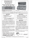
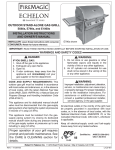
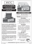
E1060i shown
IMPORTANT: READ THESE INSTRUCTIONS CAREFULLY BEFORE STARTING INSTALLATION OR USE.
WARNINGS AND SAFETY CODES
DANGER:
IF YOU SMELL GAS:
1.
2.
3.
4.
WARNING:
1. Do not store or use gasoline or other
flammable vapors and liquids in the
vicinity of this or any other appliance.
2. An LP cylinder not connected for use
shall not be stored in the vicinity of this
or any other appliance.
Shut off the gas to the appliance.
Extinguish any open flame.
Open lid.
If odor continues, keep away from the
appliance and immediately call your
gas supplier or the fire department.
CODE AND SUPPLY REQUIREMENTS: This grill
must be installed in accordance with local codes
and ordinances, or, in the absence of local codes,
with the latest National Fuel Gas Code (ANSI
Z223.1/NFPA 54), or Natural Gas and Propane
Storage and Handling Installation Code (CSAB149.1).
WARNING:
Improper installation, adjustment, alteration,
service, or maintenance can cause injury
or property damage. For proper installation,
refer to the installation instructions. For
assistance or additional information,
consult a qualified professional installer,
service agency, or the gas supplier.
This appliance and its dedicated manual shutoff
valve must be disconnected from the gas-supply
piping system when testing the system at pressures
in excess of ½ psig (3.5 kPa).
All electrical outlets in the vicinity of the grill must
be properly grounded in accordance with local
codes, or, in the absence of local codes, with the
National Electrical Code, ANSI/NFPA 70, or the
Canadian Electrical Code, CSA C22.1, whichever
is applicable.
This appliance must be isolated from the gassupply piping system by closing its dedicated
manual shutoff valve during any pressure testing
of the gas-supply system at pressures up to and
including ½ psig (3.5 kPa).
Keep all electrical-supply cords and fuel-supply
hoses away from any heated surface.
Certified to:
254-B-11e-5
ANSI Z21.58a-2008
CSA 1.6a-2008
Robert H. Peterson Co. • 14724 East Proctor Avenue • City of Industry, CA 91746
REV 4 - 1010141052
1
L-C2-281
INSTALLATION INSTRUCTIONS ET MANUEL DU PROPRIÉTAIRE
GRIL EXTÉRIEUR D’ÎLE DE GAZ D’ÉCHELON
IMPORTANT: LISEZ CES INSTRUCTIONS SOIGNEUSEMENT AVANT DE COMMENCER L’INSTALLATION OU L’UTILISATION
SÛRETÉ ET CODES D’AVERTISSEMENT
DANGER:
AVERTISSEMENT:
SI VOUS SENTEZ LE GAZ :
1. Coupez le gaz à l’appareil.
2. Éteignez-vous n’importe quelle flamme nue.
3. Ouvrez le couvercle si équipé d’un four.
4. Si l’odeur continue, gardez loin de
l’appareil et appelez immédiatement
votre département de fournisseur ou de
feu de gaz.
1. Ne stockez pas ou n’employez pas
l’essence ou d’autres vapeurs et liquides
inflammables à proximité de ceci ou
d’aucun autre appareil.
2. Un cylindre de propane non relié pour
l’usage ne sera pas stocké à proximité
de ceci ou d’aucun autre appareil.
CONDITIONS DE CODE ET D’APPROVISIONNEMENT:
Ce gril doit être installé selon des codes et des ordonnances
locaux, ou, en l’absence des codes locaux, avec l’un ou l’autre
le plus défunt Code national de gaz de carburant (norme ANSI
Z223.1/NFPA 54), et Stockage de gaz naturel et de propane
et manipulation du code d’installation (CSA-B149.1).
AVERTISSEMENT:
L’installation inexacte, l’ajustement, le
changement, le service, ou l’entretien
peuvent causer des dommages ou des
dégats matériels. Référez-vous à ce
manuel. Pour l’aide ou l’information
additionnelle, consultez un installateur
professionnel qualifié, l’agence de service,
ou le fournisseur de gaz.
Cet appareil et ses différents robinets d’isolement doivent être
démontés du gaz-fournissent le système sifflant en examinant
le système aux pressions au-dessus du ½ psig (kPa 3.5).
Cet appareil doit être isolé dans gaz-fournissent le système
sifflant par fermeture que ses différents robinets d’isolement
manuels pendant tous les essais sous pression du gazfournissent le système aux pressions jusques et y compris
le ½ psig (kPa 3.5).
•
Ce gril est pour ultilisation à l’extérieur seulement.
Si l’appareil est entreposé à l’intérieur, enlever les
bouteilles et les laisser à l’extérieur.
•
Ne pas ranger le gril immédiatement aprés l’avoir utilisé.
le laisser refroidir avant de le déplacer ou de la ranger.
Le non respect de cette mesure de sécurité pourrait
entraîner un incendie causant des dommages à la
propriété, des blessures ou la mort.
•
Ne pas utiliser cet appareil sous une surface
combustible.
•
Ne pas utiliser cet appareil sous un auvent. Le non
respect de cette mesure de sécurité pourrait entraîner
un incendie ou des blessures.
•
Dégagement minimal entre les parois latérales et
l’arriére de l’appareil et la construction combustible (45.7
cm à partir des parois latérales et 45.7cm à partir de
l’arriére).
•
•
Toutes les sorties électriques à proximité du gril doivent être
correctement fondues selon des codes locaux, ou en l’absence
de local code, avec le code électrique national, ANSI/NFPA
70, ou le code électrique canadien, CSA C22.1, celui qui est
applicable.
Maintenez tout électrique-fournissent des cordes et carburantfournissent des tuyaux partis de n’importe quelle surface de
chauffage.
RÉGULATEUR ADDITIONNEL DOIT ÊTRE INSTALLÉ
AVANT LE GRIL. VOIR LA SECTION DE CONDITIONS
D’OFFRE DE GAZ POUR LA PRESSION APPROPRIÉE
D’OFFRE DE GAZ.
Le régulareur de pression de gaz prévu avec cet appareil
de cuisson à gaz pour l’extérieur doit être utilisé. Ce
régulateur est réglé pour une pression de sortie de 5
pouces de colonne de l’eau pour le gaz naturel, et 10
pouces pour le propane.
•
Ne couvrez jamais la surface entière de cuisine ou de
gril de gauffreuses ou de casseroles. La surchauffe se
produira et les brûleurs ne seront pas très performants
quand la chaleur de combustion est emprisonnée audessous de la surface à cuire.
•
Ne pulvérisez jamais l’eau sur une unité chaude de gaz,
comme ceci peut endommager des composants de
porcelaine ou de fer de fonte.
•
Une fuite de GPL peut causer une incendie ou une
explosion si enflammée entraînant des blessures
corporelles graves ou la mort.
•
Communiquez avec le fournisseur de GPL pour les
réparations ou pour disposer de qules bouteille ou du
GPL non utilisé.
Certifié à la norme ANSI : Z21.58a-2008 / CSA 1.6a-2008
LE RÉGULATEUR INCLUS D’APPAREILS EST ÉVALUÉ
POUR LE MAXIMUM DE 1/2 (LIVRES PAR POUCE
CARRÉ). SI VOTRE OFFRE DE GAZ EST 1/2 PLUS
INSTALLATEUR : Laissez ces instructions avec le consommateur.
GRAND QUE (LIVRES PAR POUCE CARRÉ), UN
CONSOMMATEUR : Maintenez pour la future référence.
REV 4 - 1010141052
2
L-C2-281
CONTENTS
4
6
7
8
9
10
11
13
14
17
18
19
20
21
22
23
24
25
26
27
28
30
32
PARTS LIST
MODEL SPECIFICATIONS
GRILL SAFETY INFORMATION
INSTALLATION REQUIREMENTS
INSTALLING THE BUILT-IN UNIT
ELECTRICAL INSTALLATION
SAFE USE & MAINTENANCE OF PROPANE GAS CYLINDERS
IDENTIFICATION OF GRILL CONTROLS
OPTIONAL POWERHOOD
LIGHTING (IGNITION) INSTRUCTIONS
ECHELON DIGITAL THERMOMETER
ROTISSERIE INSTRUCTIONS
OPTIONAL INFRARED BURNER OPERATION
GRILLING TIPS
ACCESSORIES
FIRE MAGIC® DRIP TRAY
CARE & CLEANING
REPLACING HALOGEN BULBS
POWER SUPPLY FUSE REPLACEMENT
TROUBLESHOOTING
CONVERTING THE GAS TYPE
BURNER AIR SHUTTER ADJUSTMENT
WARRANTY
REV 4 - 1010141052
3
L-C2-281
PARTS LIST
Item Description
1
2
3
4
5
6
7
8
9
10
11
12
13
14
15
16
Stainless cooking grid set
Flavor grid
Main burner
Infrared burner
Oven lid
Warming rack
Backburner right/main
Backburner left †
Backburner cover
Heavy-duty motor
Heavy-duty rod
Heavy-duty rod knob
Meat holder
Counterbalance
Grid lifter
Convertible regulator
1
† Available only on E1060i models
‡ Not shown
8
2
4
7
12
3
9
14
31
13
6
Fig. 4-1
11
10
Items in light gray are
not available on all
models.
6
18
19
35
20
OFF
17
23
21
32
37
15
40
25
26
36 34
REV 4 - 1010141052
33
ON
16
22
To order replacement
par ts, contact your
local Fire Magic®
dealer.
5
4
24
L-C2-281
PARTS LIST (Cont.)
Item Description
17
18
19
20
21
22
23
Valve manifold
Control panel
Small knob
Large knob
Digital thermometer
Meat probe assembly
Power supply w/connector
24
Thermometer. batt. holder (3v)
25
26
27
28
29
30
31
Drip tray
Drip tray liner (set of 4)
Wire harness assembly‡
Ignitor ‡
Light Lense ‡
Halogen Bulb ‡
Zone separator
32
Smoker drawer
33
34
Power Hood motor assy. † (optional)
Power Hood switch † (optional)
35
Power Hood remote † (optional)
36
Light control switch
37
Light microswitch
38
Flex connector ‡
39
Fire Magic® cookbook ‡
40
Support screw
INSTALL ZONE DIVIDERS
Place the zone dividers as shown (Fig. 5-1)
into the grooves in the inner firewall of the grill to
allow for maximum heat control and thermometer
accuracy in each zone. Remove and store during
rotisserie use.
Fig. 5- 1
Groove
Zone divider
Groove
Front
REV 4 - 1010141052
5
L-C2-281
MODEL SPECIFICATIONS
Fire-Magic® Model Specifications Table
Table 1
Countertop to unit bottom (cut-out)*
Side to side (noncombustible cut-out)*
Front to back (noncombustible cut-out)*
Control panel width
Main burner BTU
N/P orifice drill size
Backburner BTU
N/P orifice drill size
Smoker drawer burner BTU
N/P orifice drill size
Infrared searing burner BTU
N/P orifice drill size
Optional Echelon insulating liner model #
*Note:
E660i
12"
31-1/4"
23-1/2"
32-3/4"
25,000
#42/#54
19,000
#49/#57
2,500
#68/#77
24,000
#45/#55
3176-50
E790i
12"
37"
23-1/2"
38-1/2"
32,000
#38/#53
23,000
#44/#56
2,500
#68/#77
24,000
#45/#55
3186-50
E1060i
12"
50"
23-1/2"
51-1/2"
28,000
#40/#53
15,000
#51/#58
2,500
#68/#77
24,000
#45/#55
3185-50
If using an insulating liner, consult liner instructions for counter cut-out
dimensions and installation.
TOP VIEW
Fig. 6-1
Side to side
1-1/4"
NON-COMBUSTIBLE
CABINET CUT-OUT
DIMENSIONS
10"
2 3/4"
Extra cut-out for
Power Hood only!
Front to back
11"
Countertop
Control
Panel
REV 4 - 1010141052
Control panel width
6
Countertop overhang
Lower support
L-C2-281
GRILL SAFETY INFORMATION
1. The outdoor grill and surrounding area MUST
remain clear of flammable substances such as
gasoline, yard debris, wood, etc.
blue). If burner flames are not normal, check
and clean the orifice and burner/venturi tubes
for insects and insect nests. A clogged tube can
lead to a fire beneath the grill. A proper flame
pattern will ensure safe operation and optimal
performance. Adjust the air shutter as needed
(see AIR SHUTTER ADJUSTMENT).
2. The airflow through the vent space located below
the control panel must remain unobstructed.
3. When using propane gas:
a. The required ventilation openings in the 5. The in-line gas valve or gas cylinder valve must
enclosure must be clear of debris.
always be shut OFF when the grill is not in use.
b. The propane cylinder, regulator, and rubber 6. The drip collector holes must be clear and
hose must be in a location not subject to
unobstructed. Excessive grease deposits can
temperature above 125° F (51° C).
result in a grease fire.
4. The flames on each burner burn evenly along 7. The backburner or IR burner cover must be
the entire burner with a steady flame (mostly
removed before using the burner.
WARNING: NEVER cover the entire cooking or grill surface with griddles or pans. Overheating will occur, and
burners will not perform properly when combustion heat is trapped below the cooking surface.
CAUTION: NEVER spray water on a hot gas unit.
Important:
When reviewing this units wiring connections; please refer to the wiring diagram
label affixed to the inside of the control panel.
ELECTRICAL CONNECTIONS
This grill requires 110 volt AC power to operate.
Use a grounded electrical extension cord rated for
outdoor use to connect the grill to line power.
WARNING
Electrical Grounding Instructions
For your protection against shock hazard, this
outdoor-cooking gas-appliance is equipped with
a three-pronged (grounding) electrical connector.
This appliance should be connected to a properly
grounded three-prong receptacle using a grounding
extension cord rated for outdoor use. Do not cut or
remove the grounding prong from the connector.
REV 4 - 1010141052
OVEN LIGHTS
To turn on the oven lights, open the oven, then push
the button on the far right of the grill control panel
(see SUPPLIED ITEMS list) until it clicks.
The lights will automatically turn off when the oven
door is closed and then turn on again when it is
reopened (much like the light in your refrigerator.)
If the lights do not come on, check your electrical
connection.
7
L-C2-281
INSTALLATION REQUIREMENTS
This grill is designed for outdoor use only. DO NOT use this grill under unprotected flammable surfaces.
DO NOT use this grill inside a building, garage, enclosed area, or an unprotected covered area (see
EXHAUST REMOVAL below). DO NOT use this grill in or on a recreational vehicle or boat.
Important:
The grill must have a minimum of 20" (50.7 cm) right, left, and back clearance from unprotected
combustible construction. If installing this grill in a combustible surround, the correct R. H. Peterson
insulating liner must be used.
GAS-SUPPLY PLUMBING REQUIREMENTS
The control panel MUST remain removable for servicing
(see PARTS LIST).
For natural gas or a household propane system, rigid 1/2"
(1.3 cm) or 3/4" (1.9 cm) black steel pipe or local codeapproved pipe is required to conduct the gas supply to
the unit. Contact your local gas supplier. Connect this
pipe to the required C.S.A.-approved stainless-steel flex
connector (attached). An NPT adapter has been provided
for 1/2" pipe. DO NOT use a rubber hose within the grill
enclosure. Apply only joint compounds that are resistant
to all gasses to all male pipe fittings except flare fittings.
Make sure to tighten every joint securely.
ENSURING PROPER COMBUSTION AIR AND
COOLING AIRFLOW
Proper airflow (Fig. 8-1) MUST be maintained for the
grill to perform as it was designed. If airflow is blocked,
overheating and poor combustion will result. Do not
block the 1" (2.5 cm) front air inlet along the bottom of
the control panel or more than 75% of the cooking grid
surface with pans or griddles.
Note: The 1" (2.5 cm)
front air space
also allows
access to the
drip tray.
Note: If 1/2" (1.3 cm) pipe is used with natural gas,
it should be no longer than 20' (6.1 meters).
Important:
Fig. 8-1 - Ventilation diagram
An external valve (with a removable
key) in the gas line is necessary for
safety when the grill is not in use. It also
provides for convenient maintenance.
Orient grill
so prevailing
wind blows
this way.
Left-side
hanger
EXHAUST REMOVAL
If installed or used under a patio roof, the cooking grid
area must be fully covered by an exhaust hood with a vent.
An exhaust fan with a rating of 1,000 CFM (cubic feet per
minute) (472 liters per second) or more may be necessary
to effectively remove smoke and other cooking by-products
from the area under the hood. Fire Magic Vent Hoods
are available to meet this requirement. This grill must
not be used under unprotected overhead combustible
construction. THIS UNIT MUST NOT BE LOCATED IN
A FULLY ENCLOSED AREA OF ANY KIND.
INCORRECT
Flex connector
Left-side
support wall
CAUTION: Wind blowing into or across the rear
oven lid vent (Fig. 8-2) can cause
poor performance and/or dangerous
overheating. Orient the grill so that the
prevailing wind blows toward the front of
the grill (Fig. 8-3).
CORRECT
Rear oven lid vent
CAUTION:
C
YOU MUST PROTECT
REAR OVEN VENT FROM
PREVAILING WIND
Fig. 8-2
REV 4 - 1010141052
Fig. 8-4
To prevent dangerous overheating, the rear
of the unit must have a minimum clearance
of 4" (10.2 cm) from any backsplash/wall.
GAS SUPPLY AND MANIFOLD PRESSURES:
For natural gas - normal 7" (17.78 cm) water column
(w.c.), minimum 5" (12.7 cm), maximum 10 1/2" (26.7
cm). For propane gas - normal 11" w.c., minimum 10"
(25.4 cm), maximum 13" (33 cm).
PLACE GRILL SO PREVAILING
WIND BLOWS TOWARD FRONT
OF GRILL
Fig. 8-3
8
L-C2-281
INSTALLING THE BUILT-IN UNIT
CONNECTING THE GAS SUPPLY
COUNTER PREPARATION
Consult Table 1 for non-combustible enclosure cut- CAUTION: Use only C.S.A. listed stainless-steel
flex connectors within the enclosure.
out dimensions. A Robert H. Peterson insulating
liner must be used if the counter or any supporting
WARNING
construction is combustible. Consult the instructions
that come with the liner for dimensions and A rubber or plastic connector will rupture or
additional installation information before beginning leak, resulting in an explosion or serious injury
if used inside the appliance enclosure.
the installation.
a. Run the attached flex connector routed under
the left side of the grill out of the enclosure and
to the gas stub.
This outdoor built-in grill must supported by the
stainless-steel hanger extending from the upper
portion of the grill. The hanger rests on the left, right,
and back of the countertop and on the two front
structural supports with attached adjustable screws
located below the control panel on the left and right
sides (see Fig. 9-3).
b. Turn OFF the gas supply at the source. Then
connect the 1/2" pipe adapter fitting supplied
with the stainless-steel flex connector to the
gas-supply stub. Use pipe joint compound that
is resistant to all gasses on the male pipe fitting
and tighten securely. DO NOT use pipe joint
compound to connect flare fittings.
The control panel is designed to sit flush against
the cabinet face (see Fig. 9-2). If the countertop
extends beyond the cabinet face, creating a
countertop overhang (see Fig. 9-1), it must be
cut flush with the cabinet face where the for the
width of the control panel or a gap will be created
exposing the forward portions of the left and right
side fire walls.
d. Turn all burner control knobs to the OFF position.
Turn the gas supply on. Then carefully check
all gas connections for leaks with a brush and
half-soap/half-water solution before lighting.
NEVER USE A MATCH OR OPEN FLAME TO
TEST FOR LEAKS.
Note: It is not necessary to remove the control
panel or knobs to install this unit.
e. Close the dedicated gas-supply shut-off valve,
then slide the grill into place. Do not to pinch,
kink, or damage the gas connector line.
control panel
stops here
Countertop
Proposed cutout in overhang
GAP CREATED
f. Rotate the adjustable support screws to the left
to raise and to the right to lower the respective
side of the appliance grill. Use a 7/16" open-end
wrench as needed.
Countertop
Overhang
Do not extend the support screws
so far that any part of the hanger
is raised off the counter top.
Important:
IDEAL
Flush-mounted
control panel
Fig. 9-2
Fig. 9-1
To gas
system
Battery
door
OFF
Countertop
Adjustable
support
screw
Flex
connector
Dedicated manual shut-off valve
Gas inlet pipe
Cut-out
Hanger
Bottom of
face
REV 4 - 1010141052
Bottom
of cut-out
opening
Fig. 9-3
Fig. 9-4
9
L-C2-281
ELECTRICAL INSTALLATION
POWER SUPPLY HOOKUP
Required
GFI electrical
receptacle
(not included)
CAUTION: IMPROPERLY CONNECTED WIRES
WILL CAUSE DAMAGE TO THE GRILL
AND MAY RESULT IN PROPERTY
DAMAGE AND/OR PERSONAL INJURY.
Grounded
plug
This grill includes a power supply box. When
installed, the power supply box must be located at
least 12 inches below the bottom of the grill.
Fasten the power supply box to the inside of the
enclosure, making sure the vent holes are not
blocked.
Fig. 10-2
WARNING
The electrical connections from the power supply
Electrical Grounding Instructions
box to the grill electrical systems come preThis outdoor-cooking gas appliance is equipped with a
connected.
three-pronged (grounding) plug. Do not cut or remove
the grounding prong from the plug.
CONNECTING THE POWER SUPPLY TO LINE
POWER
Plug the power supply cord into a properly wired and
inspected GFI electrical receptacle. Use a heavyduty grounded extension cord if necessary.
Fig. 10-1
ELECTRICAL SAFETY
To protect against electric shock, do not immerse cord or plugs in water or other liquid;
Unplug from the outlet when not in use and before cleaning. Allow to cool before putting on or taking off parts;
Do not operate any outdoor cooking gas appliance with a damaged cord, plug, or after the appliance malfunctions
or has been damaged in any manner. Contact the manufacturer for repair;
Do not let the cord hang over the edge of a table or touch hot surfaces;
Do not use an outdoor cooking gas appliance for purposes other than intended;
When connecting, first connect plug to the outdoor cooking gas appliance then plug appliance into the outlet;
Use only a Ground Fault Interrupter (GFI) protected circuit with this outdoor cooking gas appliance;
Never remove the grounding plug or use with an adapter of 2 prongs.
Use only extension cords with a 3 prong grounding plug, rated for the power of the equipment, and approved for
outdoor use with a W-A marking.
10
SAFE USE & MAINTENANCE OF PROPANE GAS CYLINDERS
IMPORTANT FOR YOUR SAFETY
READ AND FOLLOW ALL WARNINGS PROVIDED WITH THE PROPANE-GAS CYLINDER.
When operating this appliance with a propane-gas cylinder, these instructions and warnings MUST be observed.
FAILURE TO DO SO MAY RESULT IN A SERIOUS FIRE OR EXPLOSION.
CYLINDER/CONNECTOR REQUIREMENTS
a. Propane-gas cylinders, valves, and hoses must be
maintained in good condition and must be replaced if
there is visible damage to either the cylinder or valve. If the
hose is cut or shows excessive abrasion or wear, it must
be replaced before using the gas appliance (see e.).
b. This unit, when used with a cylinder, should be connected
to a standard 5-gallon (20 lb.) propane-gas cylinder
equipped with an OPD (Overfill Prevention Device).
The OPD has been required on all cylinders sold since
October 1,1998, to prevent overfilling.
c. Cylinder dimensions should be approximately 12" (30.5
cm) in diameter and 18" (45.7 cm) high. Cylinders must
be constructed and marked in accordance with the
Specifications for Propane Gas Cylinders of the U.S.
Department of Transportation (D.O.T.) or the National
Standard of Canada, CAN/CSA-B339, Cylinders,
Spheres, and Tubes for Transportation of Dangerous
Goods.
d. The cylinder used must include a collar to protect the
cylinder valve, and the cylinder supply system must be
arranged for vapor withdrawal.
e.
The
must
e. The pressure regulator and hose assembly used
(Fig. 11-1)
match
the
specifi
cation
for
Type
I
by
ANSI
Z
21.58-2005/
supplied with this outdoor-cooking gas appliance must
CGA
1.6-2005
(see
Fig.replacement
11-1).
be
used.
Original
and
pressure regulator
and hose assemblies must be those specified by the
manufacturer for connection with a cylinder connecting
device identified as Type I by the ANSI Z 21.58-2005/CGA
1.6-2005 (see PARTS LIST for ordering information).
f.
The use of pliers or a wrench should not be necessary. Only
cylinders marked “propane” may be used.
To disconnect: Turn the hand nut counterclockwise until
detached (Fig. 11-1).
Important:
Before using the unit, and after each time the
cylinder is removed and reattached, check
the hose for wear (see a.) and check all
connections for leaks. Turn off the unit valves
and open the main cylinder valve, then check
connections with soapy water. Repair any
leaks before lighting the unit.
CAUTION:
Always turn the propane cylinder main valve
off after each use, and before moving the unit
and cylinder or disconnecting the coupling.
This valve must remain closed and the
cylinder disconnected while the appliance
is not in use, even though the gas flow is
stopped by a safety feature when the coupler
is disconnected.
Carefully inspect the hose assembly each time before the
gas is turned on. A cracked or frayed hose should be replaced
immediately.
If the appliance is stored indoors, the cylinder must be
disconnected and removed. Disconnected cylinders must be
stored outdoors, out of the reach of children, with threaded
valve plugs tightly installed, and must not be stored in a
building, garage, or any other enclosed area.
FOR YOUR SAFETY
The propane-gas cylinder valve must be equipped with a
cylinder connection coupling device, described as Type
I in the standard defined in paragraph e. above. This
device is commonly described as an Acme thread quick
coupler.
g. If the propane-gas cylinder comes with a dust plug, place
the dust cap on the cylinder valve outlet whenever the
cylinder is not in use.
QUICK COUPLER OPERATION
To connect the regulator/hose assembly to the propanegas cylinder valve fitting: Press the hand nut on the regulator
over the Acme thread fitting on the cylinder valve. Turn the hand
nut clockwise to engage the threads and tighten until snug.
a. DO NOT store a spare propane-gas cylinder under or
near this appliance.
b. NEVER fill the cylinder beyond 80-percent full.
c. IF THE INFORMATION IN a. AND b. IS NOT FOLLOWED
EXACTLY, A FIRE CAUSING DEATH OR SERIOUS
INJURY MAY OCCUR.
Fig. 11-1 Type I Acme thread quick coupler
QCC
Type 1
valve
Pressure
relief
valve
Hand wheel
Brass Acme
thread fitting
Regulator
UL
Liquid level
indicator
(optional)
Hand nut with Acme
thread
Vent
Hose
ENCLOSURE REQUIREMENTS
FOR YOUR SAFETY, you must provide the openings listed below for drainage, replacement air, and cross-ventilation
of any storage area exposed to possible leakage from gas connections, the unit, or propane cylinders:
One side of the gas cylinder enclosure left completely open to the outside OR by providing four (4) ventilation
openings. Two (2) openings are to be at the cylinder valve level (approx. 16" [40.6 cm] above the floor) and on
opposite walls of the enclosure. Two (2) more openings must be at the floor level on opposite sides of the enclosure.
The floor-level openings must start at the floor and shall extend no higher than 5" (12.7 cm) above the floor. Each
opening must have a minimum of 10 sq. in. (64.5 cm2) of free area. To achieve the proper ventilation, you may drill
a series of holes, omit the grout from masonry joints, or replace a brick with a hardware cloth screen. If the floor
in the cabinet is raised and the space beneath the cabinet is open to the outside, the lower ventilation openings
may be in the floor.
Consult your gas supplier for ventilation and regulator requirements when connecting to a household propane supply.
11
UTILISATION SÛRE ET ENTRETIEN DES CYLINDRES DE GAZ
IMPORTANT POUR VOTRE SÛRETÉ
LISEZ ET SUIVEZ TOUS LES AVERTISSEMENTS ÉQUIPÉS DE VOTRE CYLINDRE DE GAZ DE PROPANE.
En actionnant cet appareil avec un cylindre de gaz de propane ON DOIT observer ces instructions et avertissements.
LE MANQUE DE FAIRE AINSI PEUT AVOIR COMME CONSÉQUENCE UNE INCENDIE OU UNE EXPLOSION SÉRIEUSE.
main dans le sens des aiguilles d’une montre pour engager les
CYLINDRE ET CONDITIONS ET
fils et pour serrer jusqu’à ce que douillettement. L’utilisation des
CARACTÉRISTIQUES DE CONNECTEUR
pinces ou de la clé ne devrait pas être nécessaire. Seulement
a. Des cylindres et les valves de gaz de propane doivent être
le propane marqué par cylindres doit être employé.
maintenus en bon état et doivent être remplacés s’il y a
Pour débrancher: Tournez l’écrou de main dans le sens
des dommages évidents au cylindre ou à la valve.
b. Ce gril, une fois utilisé avec un cylindre, devrait être relié à contraire des aiguilles d’une montre jusqu’à isolé (fig. 12-1).
c.
d.
e.
e.
f.
g.
un gallon de la norme 5 (20lb.) cylindre de gaz de propane
équipé d’un OPD (remplissez au-dessus du niveau le
dispositif d’empêchement). L’OPD a été exigé sur tous les
cylindres vendus depuis octobre 1.1998 pour empêcher le
remplissage excessif.
Les dimensions de cylindre devraient être approximativement
12"(30.5cm) de diamètre et 18" (45.7cm) hauts. Des
cylindres doivent être construits et marqués selon les
caractéristiques pour des cylindres de gaz de propane du
département des ETATS-UNIS du transport (D.O.T.) ou
le niveau national du Canada, du CAN/CSA-B339, des
cylindres, des sphères et des tubes pour le transport des
marchandises dangereuses.
Le cylindre doit inclure un collier pour protéger la valve
de cylindre et le circuit d’alimentation de cylindre doit être
assuré le retrait de vapeur.
Le
g. 12Le régulateur
régulateur de
de pression
pressionetetl’ensemble
l’ensemblededetuyau
tuyau(fiutilisé
1
)
fourni
avec
cet
appareil
à
cuire
extérieur
de
gaz
doivent
doivent assortir les spécifications pour le type I par ANSI
être
utilisés. Les régulateurs
et de
pression de
Z
21.58-2005/CGA
1.6-2005 d’original
(voir la figue.
12-1).
remplacement et les ensembles de tuyau doivent être ceux
indiqués par le fabricant pour le raccordement avec un
dispositif se reliant de cylindre identifié comme type I par la
norme ANSI Z 21.58-2007/CGA 1.6-2007 avec la norme ANSI
Z 21.58a -1998 d’addenda et CGA 1.6a - M98.
La valve de cylindre de gaz de propane doit être équipée
d’un dispositif d’accouplement de raccordement de
cylindre, décrit comme type I dans la norme définie dans le
e. de paragraphe ci-dessus. Ce dispositif est généralement
décrit comme coupleur rapide de fil de point culminant.
Si votre cylindre de gaz de propane vient avec une prise
de la poussière, placez le bouchon anti-poussière sur la
sortie de valve de cylindre toutes les fois que le cylindre
n’est pas en service.
Important:
Avant d’employer le gril, et ensuite chaque
fois que le cylindre est enlevé et rattaché,
examinez tous les raccordements pour déceler
les fuites. Arrêtez les valves de gril et ouvrez
la valve principale de cylindre, puis vérifiez
les raccordements avec de l’eau savonneux.
Réparez toutes les fuites avant d’allumer le gril.
ATTENTION: Tournez toujours la valve principale de cylindre
de propane au loin après chaque utilisation,
et avant de déplacer le gril et le cylindre, ou
débrancher l’accouplement. Cette valve doit
rester fermée et le cylindre a débranché alors
que l’appareil n’est pas en service, quoique
l’écoulement de gaz soit arrêté par un dispositif
de sûreté quand le coupleur est débranché.
Inspectez soigneusement l’ensemble de tuyau chaque fois
avant que le gaz soit allumé. Un tuyau criqué ou frangé devrait
être remplacé immédiatement.
Si l'appareil est stocké à l'intérieur, le cylindre doit être disconnected
et a enlevé. Des cylindres Disconnected doivent être stockés
dehors, hors de la portée des enfants, avec les prises de valve
filetées étroitement installées, et ne doivent pas être stockés dans
un bâtiment, le garage, ou n'importe quel autre secteur inclus.
POUR VOTRE SÛRETÉ
OPÉRATION DE COUPLEUR RAPIDE
a. Ne stockez pas un cylindre de gaz disponible de propane
dessous ou ne vous approchez pas de cet appareil.
b. Ne remplissez jamais cylindre au delà de 80 pour cent de
plein.
c. SI L’INFORMATION DANS “A” ET “B” N’EST PAS SUIVIE
EXACTEMENT, UN FEU CAUSANT LA MORT OU DES
DOMMAGES SÉRIEUX PEUT SE PRODUIRE.
Fig. 12-1 type coupleur rapide de fil de point culminant d’I
Volant de commande
QCC
Type 1
4
1
Ajustage de précision
3
en laiton de fil de
point culminant
Régulateur
Valve
Pour relier le regulator/hose à l’ajustage de précision de
valve de cylindre de gaz de propane: Serrez l’écrou de main
sur le régulateur au-dessus de l’ajustage de précision de fil
de point culminant sur la valve de cylindre. Tournez l’écrou de
Valve
de
décompression
UL
2
Indicateur
de niveau
de liquide
(facultatif)
Écrou de main avec le
fil de point culminant.
Passage
Tuyau
CONDITIONS DE CLÔTURE
POUR VOTRE SÛRETÉ, vous devez fournir les ouvertures suivantes ci-dessous pour le drainage, l’air de rechange, et
la ventilation en travers de n’importe quelle zone de stockage exposée à la fuite possible des raccordements de gaz,
du gril, ou du cylindre de propane:
Un côté de la clôture de cylindre de gaz a laissé complètement ouvert de extérieur OU en fournissant quatre (4)
ouvertures de ventilation. Deux ouvertures doivent être au niveau de valve de cylindre (approximativement 16" (40.6
centimètres) au-dessus du plancher) et sur les murs opposés de la clôture. Deux ouvertures supplémentaires doivent
être au niveau de plancher des côtés opposés de la clôture. Les ouvertures de niveau de plancher doivent commencer
au plancher et se prolongeront pas plus haut que 5"(12.7 centimètre) au-dessus du plancher. Chaque ouverture doit
avoir un minimum de 10 pouces carrés (64.5 cm2) du secteur libre. Pour réaliser la ventilation appropriée, vous pouvez
forer une série de trous, omettez le coulis des joints de maçonnerie, ou remplacez une brique avec un écran de tissu
de matériel. Si le plancher dans le coffret est augmenté et l’espace sous le coffret est ouvert d’extérieur, les ouvertures
inférieures de ventilation peuvent être dans le plancher.
12
IDENTIFICATION OF GRILL CONTROLS
Center right main
burner
control knob Smoker
drawer burner
control knob
Left
backburner
control knob
Fig. 13-1
Right
main burner
control knob
Right backburner
control knob
Left
main burner
control knob
Control panel
screw(s)
Center left main
burner
control knob
Drip
trays
Digital
thermometer
Woodchip
box
Power hood
control switch
(if equipped)
Light
button
E1060i control locations
Center main burner
Smoker
control knob
drawer burner
control knob
Left
main
burner
control
knob
Right
main burner
control knob
Backburner
control knob
Digital
thermometer
Drip
tray
Woodchip
box
Control panel
screw(s)
Light
button
Power hood
control switch
(if equipped)
Fig. 13-2
E660i and E790i control locations
To remove the control panel:
• Turn off the gas shutoff valve.
• Pull off the control knobs. Remove the woodchip box. Unscrew and remove
the control panel screws and washers.
• Lift the control panel up and outward, allowing it to rest on the internal chain(s).
Important: When re-installing the control panel, set it back over the front lip of
the grill so that the lid-closed-sensor plunger protrudes through the
hole on the upper right of the control panel. Prior to opening the gas
shutoff valve, be sure the control knobs are in the OFF position.
13
OPTIONAL POWERHOOD
The Fire Magic® Power Hood is available only as CONFIGURING THE LID FOR MANUAL OPENING
an Echelon E1060 factory shipped option. Read the AND CLOSING
following before using the grill.
WARNING
If the grill has been on recently, all Power Hood
Important: Grill must be connected to electrical
components are potentially hot. Wait for grill to
power to open and close lid by motor.
cool before beginning this procedure or wear
OPENING AND CLOSING THE LID BY REMOTE
heat-resistant gloves.
OR CONTROL PANEL ROCKER SWITCH
CAUTION: Do not push or pull on the lid or
its handle while it is configured for
Note: See below for manual operation procedure.
automatic operation. This could result
While set up for motorized opening and closing,
in damage to the grill.
the lid may be controlled either by the black rocker
switch on the right side of the control panel or by the To configure the lid for manual opening and closing,
remote control included with units configured with the simply remove the locking bolt using the following
procedure. This procedure requires the use of the
motorized lid option.
Allen wrench supplied with this option.
The rocker switch will lock in any one of three positions:
up–commanding the lid to open, down –commanding 1. Open the lid completely, then set the rocker switch
to the center position and disconnect electrical
the lid to close, and center–allowing the lid to hold its
power to the unit.
current position and respond to remote control.
2. Use a Phillips screwdriver to remove the stainlessFor safety reasons, the rocker switch on the control
steel motor assembly housing screw. Pull the top
panel will always override the remote control.
of the housing first up and then outward away
from the lid until the top of the shroud clears the
To enable remote control of the lid, set the rocker
lip of the motor mount beneath, then remove the
switch to center.
housing completely and set it aside (Fig. 14-3).
To open the lid, press and hold the open button on 3. Use the Allen wrench to loosen and remove the
the remote until the lid reaches the desired location.
lid motor assembly locking bolt and washer (see
Then release the remote buttons, and the lid will stay
next page).
in place.
Important: Keep this bolt and washer for later use
To close the lid, press and hold the close button on
in converting the unit back to automatic
the remote until the lid reaches the desired location.
lid operation.
Then release the remote buttons, and the lid will stay
4. Replace the motor assembly housing and
in place.
refasten.
If the rocker switch is left in the down position, remote
up commands will affect the lid only as long as the
remote button is held. When released, the motor will
move the lid back to the closed state. With the rocker
switch in the up position, the remote has no effect.
Fig. 14-3
Gear cover plate
Motor
assembly
housing
Fig. 14-2
Fig. 14-1
UP
DOWN
14
LL
PU
OPTIONAL POWERHOOD
Fig. 15-1
TURNING ON THE TRANSMITTER
Hinge bolt
Locking bolt
The transmitter has a AUTO/OFF switch, a sync. switch
and an indicator LED on it. The AUTO/OFF switch must
be in the Auto position for the remote transmitter to
control the motorized oven lid.
INSTALLING/CHANGING THE BATTERIES IN THE
TRANSMITTER
CONFIGURING THE LID FOR AUTOMATIC
OPENING AND CLOSING
The unit is shipped in this configuration, but if you have
configured it for manual operation and wish to use the
automatic open/close function again, follow this procedure
to configure for automatic operation:
Slide open the battery access door on the back of
the Power Hood remote. Remove the 12-volt camera
battery and replace it. Close the access door and
follow the instructions on synchronizing the remote
below.
SYNCHRONIZING TRANSMITTER AND
RECEIVER
The first time you turn on the transmitter or after
changing batteries in the transmitter, it is necessary
to synchronize the transmitter with the receiver.
1. Follow steps 1-4 on the previous page except
screw in the locking bolt in step 3.
To do this, use a pen to press in the synch button on
2. Switch the receiver to the AUTO position (see the receiver (Fig. 15-2). The green LED will begin to
SYNCHRONIZING TRANSMITTER AND flash. While the LED is flashing, press either the up or
down button on the remote transmitter. The LED will go
RECEIVER instructions below.
out. Then press the On/Off button on the transmitter.
The units are now synchronized. Test this by
commanding the lid up or down as appropriate.
The units may be synchronized at any time.
Sync. button
AUTO/OFF
switch
Green LED
Fig. 15-2
Note: The receiver is located in the power supply box that
must remain accessible after installation.
ON/OFF
UP
Fig. 15-3
15
DOWN
ALLUMAGE DES INSTRUCTIONS (D’ALLUMAGE)
Lisez toutes les instructions avant l’allumage, et suivez ces instructions chaque fois vous lumière le unité.
ÉCLAIRAGE ÉLECTRONIQUE
Note:
ÉCLAIRAGE MANUEL
Le unité doitélectronique
être relié à la
puissance
110VAC
pour
L’éclairage
exige
une batterie
installée
l’éclairage
électronique.
de 9 volts avec une bonne charge.
N
RRN O
SUTU
TO
ATTENTION: Attendez toujours cinq (5) minutes le gaz
pour se dégager après que n’importe quelle
1. Ouvrez les couvercles ou enlevez les couvertures des brûleurs
tentative non réussie d’éclairage.
pour être Lit.
1. Suivez les étapes 1 à 3 (à gauche).
2. Tournez tous les boutons de commande de gaz à leurs
2. Passez un allumeur brûlant de butane de long-baril ou
positions de repos.
une allumette brûlante de long-tige dans la grille à cuire
3. Allumez le gaz à sa source.
s’ouvrant au dessus du tube d’éclairage. (Fig. 16-2). Pour
des backburners, tenez la flamme contre le matériel
Note:
N’ouvrez
LisezRead
l’établissement
ici
setting
(OUTRE
de montrer)
here
perforé du backburner. Pour des sideburners, tenez la
pas plus d’une
flamme contre le brûleur.
va
l
ve
à
l
a
fo
i
s
FDFE
O
NE
R
R
pour
l’éclairage
OFF
U
3. Tout en tenant l’allumette
l’allumette ou
ou la
la flamme
flamme plus
plus légère
légère
UT T
O
électronique ou
TO
au dessus du tube d’éclairage
d’éclairage ou
ou àà côté
côté du
du brûleur
brûleur
manuel.
(sideburner
et backburner
seulement),
diminuez
le
(backburner seulement),
diminuez
le bouton
et tout en
HIGH to
Utilisation
LIGHT
SALUT
bouton
et le
tout
en de
pressant
le tourdésirés
de commande
pressant
tour
commande
il dans désirés
le sens
(haute)
Enfoncez
ilcontraire
dans le des
sensaiguilles
contraire
desmontre
aiguilles
d’une
montre
d’une
dans
la position
à la lule bouton
mière
pour
dans
la position
LÉGÈRE
de HI. Enlevez
l’allumeur
ou
LÉGÈRE
de
HI.
Enlevez
l’allumeur
ou
assortissez
quand
tourner
assortissez
quand leetbrûleur
et libérez
le bouton
le brûleur s’allume,
libérezs’allume,
le bouton
de commande.
Fig. 16-1 - bouton de commande
de commande.
HI
LIGHT
LOW
4. Diminuez le bouton de commande désiré, et tout en
pressant le tour il dans le sens contraire des aiguilles
d’une montre dans la position LÉGÈRE de HI. Une fois
que le brûleur s’allume, libérez le bouton de commande.
ATTENTION :
Si un brûleur ne s’allume pas dans cinq
(5) secondes d’allumer le bouton de
commande, enfoncez le bouton et tournezle à la position de repos. ATTENDEZ CINQ
(5) MINUTES avant de répéter l’étape 4. Si
vous sentez le gaz, suivez les instructions
sur la couverture de ce manuel. Si les
brûleurs ne s’allument toujours pas après
que plusieurs tentatives, se rapportent aux
instructions pour l’éclairage manuel.
Tube
d’éclairage
Plus léger
5. Répétez l’étape 4 pour que chaque brûleur additionnel soit Lit.
Important:
4. Si le brûleur ne s’allume pas, enfoncez immédiatement
le bouton et tournez la valve à AU LOIN. ATTENDEZ
CINQ (5) MINUTES avant de répéter les étapes 2 à 4
des instructions manuelles d’éclairage.
En allumant le brûleur sous le tiroir de
saveur/fumeur, enlevez d’abord le tiroir
de sorte que le brûleur puisse être
facilement vu. Remplacez alors le tiroir
après que le brûleur soit Lit.
Fig. 16-2 - Éclairage manuel
ARRÊT DU UNITÉ
Pour couper le unité, diminuez chaque bouton de commande
de valve et, et tout en pressant tour il dans le sens des
aiguilles d’une montre à la position de repos.
Fermez toujours la valve de la fourniture de gaz après chaque
utilisation du unité.
EN EMPLOYANT UN RÉSERVOIR DE PROPANE PORTATIF
Des réservoirs de propane sont équipés d’un dispositif
d’arrêt de sûreté qui peut ne pas causer le bas ou aucunes
pression de gaz/flamme aux brûleurs si le fonctionnement
et l’allumage des instructions ne sont pas suivis exactement
(voir la note importante dans la section de dépannage pour
plus de détails.)
16
LIGHTING (IGNITION) INSTRUCTIONS
Read all instructions before lighting, and follow these instructions each time you light the unit.
ELECTRONIC LIGHTING
MANUAL LIGHTING
Grill must be
connected
to 110VAC
power
for
Note: Electronic
lighting
requires
an installed
9-volt
electronic
lighting.
battery
with
a good charge.
1. Open lid(s) or remove cover(s) from burner(s) to be lit.
CAUTION: Always wait five (5) minutes for gas to
clear after any unsuccessful lighting
attempt.
2. Turn all gas control knob(s) to their OFF position(s).
2. Insert either a burning long-barrel butane lighter or
a burning long-stem match through the cooking grid
opening to the top of the lighting tube. (Fig. 17-2).
For backburners, hold the flame against the
p e r fo r a t e d m a t e r i a l o f t h e b a c k b u r n e r.
For sideburners, hold the flame against the burner.
3. Turn on the gas at its source.
Read
Readsetting
setting here
(OFF position
shown)
here
TT oO
F
FFF
OO
TTUu
OFF
ONON
rnRN
TuTU
ToT O
RrNn
HI
LIGHT
Press
knob in
to turn
Note: DO NOT
turn on more
than one valve at
a time for either
electronic or
manual lighting.
top
of
3. While holding the
the match
matchor
orlighter
lighterflame
flameatatthe
the
top
thethe
lighting
tube
of
lighting
tubeorornext
nexttotothe
theburner
burner (backburner
(sideburner
only),backburner
depress the
desired
control
and
while
and
only),
depress
the knob
desired
control
pressing
turn
it
counterclockwise
to
the
HI
LIGHT
knob and while pressing turn it counterclockwise to
position.
Remove
the Remove
lighter or
the
the
HI LIGHT
position.
thematch
lighterwhen
or match
burnerthe
lights,
and release
the control
when
burner
lights, and
releaseknob.
the control
knob.
HIGH to
Use
LIGHT
HI
(high)
to light
LOW
Fig. 17-1 - Control knob
4. Depress the desired control knob, and while pressing
turn it counterclockwise to the HI LIGHT position.
Once the burner lights, release the control knob.
CAUTION:
If a burner does not light within five (5)
seconds of turning on the control knob,
depress the knob and turn it to the OFF
position. WAIT FIVE (5) MINUTES
before repeating step 4. If you smell
gas, follow the instructions on the cover
of this manual. If the burners still do not
light after several attempts, refer to the
instructions for manual lighting.
4. If the burner does not light, immediately depress
the knob and turn the valve to OFF. WAIT FIVE
(5) MINUTES before repeating steps 2 through 4
of the MANUAL LIGHTING instructions.
Lighting
tube
Lighter
Fig. 17-2 - Manual lighting
5. Repeat step 4 for each additional burner to be lit.
Important:
1. Follow steps 1 through 3 (left).
When lighting the burner under the
flavor/smoker drawer, first remove
the drawer so that the burner can be
easily seen. Then replace the drawer
after the burner is lit.
SHUTTING OFF THE UNIT
To shut off the unit, depress each valve control knob
and, and while pressing turn it clockwise to the OFF
position.
Always close the valve from the gas supply after each
use of the unit.
WHEN USING A PORTABLE PROPANE TANK
Propane tanks are equipped with a safety shutdown
device that may cause low or no gas pressure/flame
at the burners if operating and lighting instructions
are not followed exactly (See important note in the
TROUBLESHOOTING section for more details.)
17
ECHELON DIGITAL THERMOMETER
Your Echelon outdoor gas grill comes with a digital
thermometer with built-in timer.
The thermometer
is located on the
control panel
between the
control knobs.
Fig. 18-1
Fig. 18-6
Plug in meat probe
as shown in Fig.
18-6.
“P” indicates
meat probe
reading
Fig. 18-5
Auto Off
For best performance and
temperature readings center
zone separators properly
between each burner (see
parts list).
Max. displayable
meat probe temp
shown.
212˚F
P 142.4˚F
Setting temperature alarm
Actual temp.
(dashes when
out of range)
Timer
Press
repeat edly
Start
/Stop
Start
/Stop
˚C/˚F
Temp
Fig. 18-7
Alarm set temp.
Press
Set
Digit
blinks
Set
Set
ON/OFF
Battery tray
door
Meat probe
plug
Thermometer 2 ‘AA’
battery access (Fig
18-7).
Fig. 18-2
Meat
probe
Meat probe
handle
or
Set
Start
/Stop
Set
Unt il
desired
digit
displayed
Set
Press
Ret urn
t o t em p.
m ode
Press and hold to turn thermometer on or off.
Changing temperature units
(Celcius/Farenheit)
Press any button to turn backlight on for 5 seconds
Fig. 18-3
Displayed when
timer running
“1” indicates
one of the 3
burner zones
Auto Off
Max. displayable
oven temp. shown
932˚F
1 358.2˚F
hold
3 sec.
Alarm set temp.
Actual temp.
(dashes when
out of range)
Tem p
Start
/Stop
˚C/˚F
press
press
Unit
changes
Display
shows
C or F
Tem p
Back t o
t em p.
display
Setting and starting the count-down timer
Set
ON/OFF
Temp
Timer
hold
3 sec.
Set
Press once to start/stop temp. alternation
between probe and oven or return to temp.
display mode from another mode.
Fig. 18-4
Hours
Timer Mode
0:14
Minutes
Start
/Stop
˚C/˚F
Set
ON/OFF
Temp
Timer
Press once to enter timer mode.
or
Unt il
desired
num bers
displayed
Press
repeat edly
Cout down time.
or
Timer is
counting down
when colon is
blinking
Auto Off
Timer
Displays
t im e
m inut es
fl ashing
Press
repeat edly
Unt il
desired
num bers
displayed
Press
Timer
Displays
t im e
hours
fl ashing
Press
Press
Timer
Num bers
st op
frashing
Set
Colon
blinks
count down
t o alarm
st art s
Note: Press any key to silence alarm when beeping.
Alarm will not sound if timer is turned off.
Set
Press to enter/exit set time mode.
18
ROTISSERIE INSTRUCTIONS
Backburner cover
Rot isserie
rod bracket
Warm ing rack
Rot isserie rod
rear bracket
A
B
Rot isserie
m ot or
bracket
1
Rot isserie
rod
and
knob
2
Rot isserie
m ot or
Meat
holders
Fig. 19-1
Count erbalance
Heavy- dut y
Rot isserie m ot or
2
Rod drive socket
1
Rot isserie m ot or
slot s ( 4)
Rocker
swit ch
Fig. 19-2
Fig. 19-3
Backburner
( unlit )
Drip t ray
liner
loosen/
t ight en
CAUTION: WHEN USING THE BACKBURNER; KEEP
THE OVEN LID CLOSED TO PREVENT HEAT
LOSS, PROVIDE PROPER CONVECTION,
AND PROVIDE PROPER VENTING. THIS WILL
ENSURE EVEN COOKING TEMPERATURES.
DO NOT KEEP YOUR OVEN LID OPEN DURING
ROTISSING, AS THIS MAY CAUSE PERSONAL
INJURY, OR IN SOME CASES, IN WINDY
CONDITIONS, DAMAGE TO THE GRILL.
1. Remove warming rack, backburner cover, cooking grids,
and zone separators. Leave the flavor grids on if possible.
2. Slide rotisserie motor fully onto motor bracket (right side,
Fig. 19-1 and 19-2).
3. Remove rotisserie rod from rear bracket (Fig. 19-1) and
attach knob if necessary.
4. Slide the left meat holder onto the rod (and tighten), the
meat onto the rod and into the holder, followed by the
right meat holder onto the rod and into the meat as shown
in Fig. 19-3. Tighten the right meat holder. Be sure the
meat is centered and balanced as well as possible.
7. Hold both ends of the rod so it settles freely (do not grip
tightly). Allow the rod to rotate until the heavy side of the
meat rests downward.
8. The counterbalance may then be attached to even weight
distribution. Slide counterbalance onto rod next to the
meat holder. Loosen the arm and point it upward opposite
the heavy side of the meat. Tighten the arm.
9. Slide the counterbalance weight up or down the arm until
the rod rotates most evenly then tighten thumb screw
(Fig. 19-4 and Fig. 19-5).
10. Insert the pointed end of the rod into the motor drive
socket and the groove next to the knob into the left
support bracket.
11. To keep drippings off the burners and simplify cleanup,
place Fire Magic® drip tray liners under the meat, if
desired (Fig. 19-3).
12. Plug-in the rotisserie motor and press the rocker switch
to start (Fig. 19-2).
13. Light backburner per lighting instructions in this manual
(or on drip tray handle) and close oven lid.
Important: Turn the backburner to low or off when
stopping the rotisserie to prevent overcooking.
Fig. 19-5
Fig. 19-4
Backburner
( lit )
Arm
slide
Thumb
screw
Weight
Left support bracket
19
OPTIONAL INFRARED BURNER OPERATION
The Fire Magic® infrared (IR) searing burner (optional)
WARNING
cooks with a powerful radiant heat.
Only handle the infrared burner cover when the
grill is cold or with a well-insulated long-handled
tool or heat resistant gloves.
Cover
SIDE VIEW (with cover on)
Cut-out for
Flash tube
Flash tube
Ignitor
electrode
NO foreign
objects
Ignitor
electrode
Drippings
and other
Airborne liquids
dust or
grease
Cover
Flash
tube
Food
particles
or debris
Fig. 20-1
OFF
Fig. 20-2
LOW
• For cleaning purposes; always leave your burner
on (after cooking) for an additional 5 minutes, to
allow for a burnoff period. This is important to
keep your burner clean and operating properly.
As the burner is self cleaning (at full temperature);
avoid the use of cleaners or abrasives.
HI
LIGHT
Light the infrared burner following the LIGHTING
INSTRUCTIONS in this manual or printed on the
drip tray. Follow these guidelines when operating the
Infrared burner:
• DO NOT place food on the cooking grid until
the IR burner glows orange (Fig. 20-3). Drippings
are heated and evaporate instead of sticking to and
impairing burner function.
Burner ceramic must be protected with cover when
burner is not in use.
SIDE VIEW
(burner on HI LIGHT
and glowing orange)
Ignitor
electrode
Flash
tube
• When not in use, always cover the infrared burner
with the stainless-steel cover. This protects the
burner from drippings (from other cooking), airborne
particles, and foreign objects (Fig. 20-2).
• Do not strike or scratch the burner ceramic as it
may chip, crack, or break (Fig. 20-2).
Note: Digital thermometer does not give accurate
readings for infrared burners.
LOW
OFF
HI
LIGHT
Fig. 20-3
Important: When grilling with the infrared burner,
always place a cooking grid above it.
The cooking grid must be removed for
rotisserie cooking.
Drips and particles evaporate before hitting infrared
burner when cooking at the maximum setting.
CAUTION: Never attempt to operate the IR burner
with the protective cover in place.
20
GRILLING TIPS
The art of grilling involves learning the nuances of your front edge, where it rises rapidly to a fairly even
grill and knowing how various cuts of meat and other temperature reflected by the digital thermometer.
foods cook on it under different settings and conditions. The heat continues to rise gradually until it reaches a
maximum directly above the place where the two lobes
Each grill will be unique due to its configuration
of each burner connect (see Fig. 21-2). From there to
and how it is positioned or installed. This section
the back of the grill, heat diminishes moderately. This
contains information about how Fire Magic grills were
supports the desired temperature for the warming
engineered, which will help you in learning how your
rack and prevents heat from becoming excessive at
grill responds to the way you use it.
the back fire wall of the grill.
COOKING ZONES
Your grill is divided into three cooking zones, each
corresponding to a burner. Burners are numbered
starting at one (1) on the left, going to three (3) on the
right (see Fig. 21-1). The cooking zones are monitored
by the digital thermometer.
GRILL HEAT DISTRIBUTION - IR BURNER
Infrared burners are designed for even, searing
heat across their whole surface. Because the heat
is radiant, it tends to heat the food you are cooking
directly without heating the air around it as much as
a conventional burner.
Note: E1060 models contain an additional cooking
zone, on the far left of the grill. This zone is not SMOKER DRAWER USE
monitored by the digital thermometer.
When using a single cooking zone with the smoker
Each cooking zone temperature is designed to be drawer, use zone 1. It will minimize burner heat on the
flavor drawer and maximize a circulating convection
controlled individually by the burner control knob.
current that will draw the smoke flavor into the food.
Specific zones are better suited to specific types of
cooking because of features such as being adjacent
WIND CONSIDERATIONS
to a fire wall or away from the smoker drawer.
Wind direction can have an effect on the grill,
especially with the oven open. For maximum stability
GRILL HEAT DISTRIBUTION - MAIN BURNERS
and convenience, position the grill so that the oven
The heat level at each part of the grill has been opens toward any prevailing wind (Fig. 21-1).
engineered for specific purposes. Knowing the heat
distribution for each burner will allow you the best
Fig. 21-1
possible food positioning when grilling.
CAUTION: Even the coolest part of the grill is too
1
hot to be touched during operation of
the grill.
2
3
Orient grill so prevailing wind
blows in this direction
The front of the grill is designed, for safety reasons,
to be the coolest part of the grill. If you look directly
down on the grill top, while it is off and cool, you can
see this portion of the grill, where the front end of each
burner stops and the slope of the inner grill fire wall
begins. This area also loses heat most rapidly when
the oven lid is opened (see Fig. 21-2).
Fig. 21-2
Medium heat
High heat
From the front of the grill moving toward the back,
the heat rises gradually until just above the burner’s
Medium heat
Low heat
21
ACCESSORIES
THE GRILL BRUSH (OPTIONAL)
THE WARMING RACK (if equipped)
Purchase a Fire Magic® stainless-steel grill brush (sold
separately) to keep your grill cleaner. It comes with
scraper for large particles and a replaceable head with
brass bristles for overall cleaning.
The warming rack (Fig. 22-2) is packed separately.
To install the warming rack, lift the front of the rack
up slightly and insert the rack hangers into the two
holes in the back of the inner oven hood just above the
backburner. Then lower the front of the rack into a level
position to lock the rack in place.
To remove the warming rack, lift up on the front of the
rack until the rack hangers pull free from their supporting
holes.
Fig. 22-1
Note: Removing the warming rack before using the
rotisserie will leave more clearance for the
meat being cooked.
Grill brush with replacement head
THE COOKING GRID LIFTER
Hold the grid lifter by gripping the center section with the
prongs pointing down (use an oven mitt or heavy glove
if the grill is hot). Insert the notched end of the grid lifter
into the cooking grid, in front of the midway point (front to
back; Fig. 22-3), and central (left to right; Fig. 22-4).
Twist the grill lifter (clockwise or counterclockwise) so
the handle is parallel to the grill rods. This “seats” the
spiked end of the grid lifter between two rods, enabling
you to safely lift out the grid. Lift slowly and adjust the
grid lifter, if necessary, for balance.
Fig. 22-2 Warming rack in place inside oven
THE DRIP TRAY
The drip collection system allows you to brush or scrape
excess dried residue from the grilling area directly into
the drip tray (see PARTS LIST for drip tray location).
To simplify cleanup when using the rotisserie, you may
place a baking pan or foil under the rotisserie on top of
the burners to collect the drippings. Clean the drip tray
after each use.
Fig. 22-3
Fig. 22-4
Placement of the grid lifter in cooking grid
THE FLAVOR GRID(S)
Place each flavor grid directly over a burner. The solid
areas of the grid should rest over the tabs found on the
burner. See Fig. 22-6.
22-5.
FLAVOR FROM WOOD CHIPS OR CHARCOAL
You can add wood chips, wood chunks, or the natural
wood charcoal of your choice to the smoker drawer (Fig.
22-5) or the flavor grid (Fig. 22-6). Heat wood chips in the
smoker drawer by lighting the smoker burner using the
smoker control and zone 2 ignitor. When using the flavor
grid, we recommend placing wood outside the direct
cooking zone or wrapping it in perforated aluminum foil.
Soaking wood before use will slow burning and increase
smoke flavor. Wood and charcoal ash will remain in the
flavor grid and drawer after use. Either can be easily
removed and cleaned when unit has fully cooled. The
smoker drawer is water-tight, allowing liquid flavorings
to be added as well.
Note: This allows heat from the burners to be evenly
distributed throughout the cooking area. The
flavor grids heat and cool quickly, making the
grill very responsive to changes in heat from
the burners.
Fig. 22-5
Wood chip smoker drawer
22-6
Fig. 22-5
Flavor grid
22
FIRE MAGIC® DRIP TRAY
Drippings from grilling flow through specially
designed channels and collect in the drip tray.
Check the drip tray regularly and empty when
required.
Fig. 23-1
Fig. 23-2
Pull out the drip tray and place liner
Your grill includes a pack of four (4) Fire Magic®
drip tray liners (Fig. 23-1). For your convenience
in cleanup, place a liner into the drip tray before
grilling.
To fit a liner into the drip tray, pull out the tray and
set it on a flat, level surface. Place the liner in the
drip tray as shown in Fig. 23-2 and carefully insert
the tray back under the control panel.
Note: Be sure that the liner is properly placed into
the the drip tray. The front of the liner must
fit under the drip tray's lighting instruction
plate (see 23-3 detail).
Fig. 23-3
Be sure liner fits under lighting instruction
After each use, wait for the grill to cool and carefully
pull out the drip tray to check it. When a liner is
nearing full, carefully lift it out of the drip tray, lifting
with both hands to keep the tray level until it is
safely discarded. Then insert a new drip tray liner.
Order more drip tray liners through your local Fire
Magic® dealer.
Note: The foil tray liner is also useful for setting on
burners to cover them and catch drippings
directly during rotisserie only cooking.
Note: There
are easy
to follow
instructions
For models
with
matchlighting
holders
attached
etched
onto
thetray,
top place
of thethe
dripmatch
tray handle.
inside the
drip
holder
off to one edge of the pan (Fig. 23-3). If
necessary, mold the foil liner around them
and the other features of the tray to create
enough clearance space to open and close
the tray without catching the liner.
23
CARE & CLEANING
CARE AND CLEANING
APPLIANCE MUST BE COMPLETELY COOL WHEN
CLEANING. DO NOT SPRAY ANY CLEANER OR
LIQUIDS ON THE APPLIANCE WHEN HOT.
Stainless steel surfaces when exposed to
temperatures produced by the grilling process will
change color. The stainless steel will change color
from silver to brown and blue. This can be removed by
using Fire Magic Stainless Steel Cleaner (3581-1).
Clean your appliance by fi rst using Fire Magic
Barbecue and Grill Cleaner (part #3580-1) to
remove grease and dirt. Always wipe with the grain
(See Fig. 24-1). Next, use Fire Magic Stainless
Steel Cleaner (3581-1) to restore the stainless steel
color (Note: not for mirror finish). Finish by wiping
your appliance down using Fire Magic Polish Wipes
(3586-1). To clean the mirror panel (if applicable),
use a quality brand glass cleaner only, not any
of the cleaners mentioned above.
Clean your appliance at least once a month.
in
Wipe with gra
Fig. 24-1 - Wipe with grain
PROTECTING YOUR APPLIANCE FROM THE
WEATHER
An optional heavy-duty cover will protect your
appliance’s finish and protect your investment. The
water repellent cover will protect your appliance
from the weather. Always cover your appliance
when not in use. (Allow to cool before covering.)
If your appliance is installed in a seaside (salt air) or Please specify the model number and serial
poolside (chlorine) location, it will be more susceptible number of your appliance when ordering a cover.
to corrosion and must be maintained/cleaned more
frequently. Do not store chemicals (such as chlorine
IMPORTANT
or fertilizer) near your stainless steel appliance.
Due to the nature of stainless steel, surface iron
oxide deposits may appear. Do not be alarmed –
these deposits are removable with stainless-steel
cleaner through prompt and periodic maintenance.
If not attended to promptly, permanent pitting may
occur.
Check and clean the burner ports and burner carryover slits for blockage at least annually by removing
the burner (see orifice changing instructions) and
visually inspecting the burner inlet for insects and
nests. A clogged burner can lead to a fire in the
bottom of the appliance. (For Fire Magic grills use
Maintenance Kit part #MK-1.)
The inside of the appliance may be cleaned
periodically with oven cleaner if desired. Follow the
oven cleaner instructions for proper use.
Be careful not to get oven cleaner on the outside
surface of the appliance as it can permanently
damage the finish.
By following these recommendations, you will enjoy
the beauty and convenience of your appliance for
many years to come.
24
IN THE EVENT OF A GREASE FIRE,
IMMEDIATELY SHUT OFF THE MAIN GAS
VALVE TO THE GRILL. KEEP THE LID OPEN
AND ALLOW THE FIRE TO EXTINGUISH
ITSELF. A THOROUGH INSPECTION BY A
TRAINED SERVICE TECHNICIAN SHOULD
BE CONDUCTED BEFORE FUTURE USE OF
YOUR GRILL. THE SERVICE TECHNICIAN WILL
CHECK THE SYSTEM FOR GAS LEAKS AND
WILL CHECK ALL ELECTRICAL WIRING FOR
DAMAGE. ALL GAS LEAKS AND WIRING MUST
BE REPAIRED PRIOR TO FUTURE USE.
REPLACING HALOGEN BULBS
Fire Magic® Echelon grills are all engineered with the
conveniences of electrical power for illuminating and
igniting the grill.
5. Wearing a pair of gloves, reach into the fixture,
gently grab the bulb, and pull it straight out of the
fixture so that the two pins at the base of the bulb
come all the way out.
To replace any Echelon oven light, follow the
instructions below.
Fig. 25-2
Bulb
Socket
WARNING
To protect from potentially sharp sheet metal and
glass, wear gloves and safety glasses during this
procedure.
Fixture
Curved
cut-out
top of
lens
1. Turn all burner control knobs to the OFF position
and shut off the gas supply to the grill at the source
(tank valve for propane units or gas line shut-off
valve for natural gas units.)
2. Disconnect supply of external electrical power to Important: Bulb is halogen. DO NOT TOUCH with
the grill.
bare hands. Oils from hands drastically
reduce bulb life.
CAUTION: Wait for the grill, oven, lens, light bulb,
Note: It may be helpful to rock the bulb gently
and fixture to cool before proceeding to
backward and forward while pulling it out.
the next step.
3. Open the oven lid.
Fig. 25-3
Socket
Important: Place one hand directly below the glass
lens and prepare to catch it when it is
detached.
Holes
4. Carefully insert a standard flat head screwdriver
or thin plastic spatula between the glass lens and
the stainless steel on which the light is mounted
Prongs
Fig. 25-1
Bulb
6. Inspect the old bulb for broken glass or filament.
Note: It may be beneficial to test a suspect bulb
in one of the other light fixtures known to be
working and turn the power back on to be
certain the bulb is actually not working.
Lens
7. Insert the new bulb into the socket so that both pins
slide all the way into the two holes in the bottom
of the socket.
and gently pry the glass lens out in such a way
that the stainless steel is not scratched (twisting
the screwdriver handle, for instance). Catch the
lens and set it safely aside.
8. Place the lens back into the fixture opening with
the curved cut-out on the bottom and snap it back
into place.
Note: You may wish to take this opportunity to clean
the lens with a standard household window
cleaner and then dry it completely.
25
POWER SUPPLY FUSE REPLACEMENT
1. Locate the power supply box inside of the island
enclosure (reference the PARTS LIST).
Fig. 26-1
2. Using a phillips screwdriver, remove the 4 large
screws found on the cover of the power supply
box (see Fig. 26-1).
3. Disconnect the power supply cord. Then
disconnect the wire harness and ground wire
(see Fig. 26-2). Completely remove the box from
the enclosure for ease of fuse replacement.
4. Remove the 4 small screws found on the cover
of the power supply box (see Fig. 26-3).
Remove 4 large screws
Disconnect
here
Fig. 26-2
Note: The 2 center screws do not need to be
removed.
5. Carefully open the box by pulling its cover away.
You may need to feed the wire harness into the
box to provide enough slack to open on the
other end. Then “push in and twist” the fuse
holder (red wire), exposing the fuse. See Fig.
26-4.
6. Replace the fuse accordingly (3AG 2 AMP).
Disconnect wire harness and ground wire (and power cord)
Fig. 26-3
Remove 4 small screws
Fig. 26-4
Carefully open box and replace fuse (red wire)
26
TROUBLESHOOTING
If you have trouble with this Fire Magic® grill, please use this list to identify the problem. By trying one or more of the solutions to
the possible cause, you should be able to solve the problem. If this list does not cover your present problem, or if you have other
technical difficulties with the grill, please contact your local Fire Magic® dealer or visit our web site at www.rhpeterson.com.
PROBLEM
Ignition system
failure
Insufficient heat
Uneven heating
Thermometer
malfunction
POSSIBLE CAUSE
CORRECTION
1. Power source not hooked to power supply
1. Hook external power to grill.
2. Improper air shutter adjustment
2. Adjust air shutters.
3. Ignition wire disconnected
3. Plug wires back into ignition switches.
4. Low gas pressure
4. Have the gas co. check pressure at grill.
5. Front carry-over port
5. Clean burner ports.
6. Blown fuse in power supply box
6. Replace the fuse. Reference the POWER
SUPPLY FUSE REPLACEMENT section.
7. Igniter switch malfunction
1. Improper air shutter adjustment
7. Contact dealer for replacement.
1. Adjust air shutters.
2. Using propane orifice for natural gas
2. Check/change orifices.
3. Low gas pressure/flame (propane)
3. Shut off all valves, including propane tank, and
follow lighting instructions exactly. (See important
note* below.)
4. Low gas pressure/flame (natural)
4. Have the gas co. check pressure at grill.
1. Burner ports partially blocked by debris
1. Remove burners and clean out ports.
2. Small spiders or insects in burner
2. Inspect burners and orifices for spider webs or other
debris that may block flow.
3. Improper air shutter adjustment
3. Adjust air shutter.
1. Battery charge low
1. Replace batteries. Check connections to batteries.
1. Valve "Low" setting needs adjustment
1. Light burner on HIGH, immediately turn to LOW
setting. Remove knob from valve and using a small
flat screwdriver, slowly turn the adjustment screw
in the stem, a little at a time (30° to 45°), in either
direction, until the flame is approximately 1/4" in
height from burner ports.
1. Rotisserie out of balance
1. Adjust rotisserie counterbalance.
1. Elec. socket circuit breaker is tripped
1. Reset circuit breaker (See Fig. 27-1).
Burner goes out
on LOW
Rotisserie noisy
Rotisserie doesn’t
turn but lights work
Table 2
* Important: Propane tanks are equipped with
a safety shutdown device that may
cause low or no gas/flame at the
burners if operating and lighting
instructions are not followed exactly. If
you suspect the propane tank safety
shutoff is in effect, shut off all burner
control valves and the propane
tank valve. Then read and follow
the LIGHTING INSTRUCTIONS
exactly. Lighting instructions are
located in your owner’s manual and
printed on the grill’s metal drip tray.
If the problem persists, continue
troubleshooting, or contact your
local dealer or R. H. Peterson for
assistance.
27
CONVERTING THE GAS TYPE
REGULATOR CONVERSION
Required tools:
•
Phillips-head screwdriver (#2 medium)
The gas regulator, located behind the control panel, must
• Needle-nose pliers
be set for the type of gas used to fuel the grill. To check
• 3/8" hex nut driver (deep socket)
the regulator setting, remove the cap in the center of the
• 5/16" hex nut driver
regulator (Fig. 28-1). Holding the cap vertical (see Fig.
28-2), the letters at the bottom of the plastic stalk indicate CHANGING THE MAIN BURNER ORIFICES
the gas type for which the regulator is currently configured.
If the bottom of the regulator stalk does not indicate the 1. Remove the cooking grid from above the burner you
gas connected to the grill, remove the stalk from the cap,
are working on by lifting it first from the front and set
it aside.
invert, and replace into center of cap. Replace cap on the
regulator, screwing down until snug.
2. Remove the flavor grid from above the burner you
are working on and set it aside.
Gas regulator
Note the cap on top.
3. Remove the cotter pin from the left or right rear
burner anchoring peg by
pulling it straight out of the
cotter pin hole using fingers
Cotter pin
or needle-nose pliers (Fig.
28-3).
Read gas
type here.
(LP shown)
Fig. 28-1
Fig. 28-2
CAUTION: T h e b u r n e r i s Main
heavy.
burner
GAS ORIFICE CONVERSION
4. Lift the back end of the burner
This Fire Magic® grill comes from the factory configured
out of the anchor peg holes,
Fig. 28-3
for one type of gas as marked on the label behind the
then move the burner toward
control panel. When the grill is converted, this label
the back of the grill to clear
the gas inlet and set it aside.
must be replaced or updated to identify the new gas.
Each burner has a brass orifice, which can be replaced
and must match the gas being used. When converting
the grill to a different gas, each burner’s orifice must
be replaced with the corresponding orifice for the new
gas.
5. Use a 3/8" hex nut driver to remove the exposed
orifice (Fig. 28-4) and replace it with the correct
orifice for the new gas. (See
Table 1 at the beginning of this
document for orifice sizes.)
Natural-gas to propane-gas conversions using a
tank internal to a portable grill require installation of
a propane tank holder (not included) for safety and
compliance with the ANSI standards referenced on
the cover of this document. This tank holder must be
purchased separately from the manufacturer.
6. Replace the burner by first Orifice
sliding the open cylindrical
end of the burner around
the orifice, enveloping it and
centering on it, then lower the
back end anchor pegs into the
Fig. 28-4
anchor peg holes.
Consult Table 1 at the beginning of this document to
determine the proper orifice sizes for each burner.
Note: It is critical to the continued safe functioning
of the burner that the orifice is centered and
completely inside the burner gas conduit.
7. Reinsert the cotter pin into the right rear burner
anchor peg using fingers or needle-nose pliers.
It is critical to the operation of each burner that its orifice
be fully inserted into the center of its orifice opening.
WARNING
Hazardous overheating will occur if a natural-gas
orifice is used with propane gas.
8. Replace the flavor grid and then the cooking grid so
that the cutout section of the cooking grid is lined
up with the lighting tube.
Repeat these steps for each main burner.
CAUTION: Make sure the grill is at a safe
temperature and isolated from gas and
CHANGING THE BACKBURNER ORIFICE (IF
electrical supplies before beginning.
EQUIPPED)
For your safety, exercise caution, and make sure you 1. Remove the warming rack if installed and set it aside.
have adequate hand protection, such as gloves, when
2. Remove the backburner cover.
handling metal parts.
3. Unscrew all backburner access plate screws using
a Phillips-head screwdriver and set them aside.
28
CONVERTING THE GAS TYPE
4. Remove the back panel by pulling the bottom toward
the front of the grill and rotating it upward and
outward until the two top tabs attached to back wall
of the oven can be removed from the slots in the top
of the plate.
5. R e m o ve t h e b a c k b u r n e r
assembly retaining screw on
the lower left of the backburner
using a Phillips-head
screwdriver and set it aside.
6.
Pull
wire from the
ignitor
6. Pull the
the backburner
assembly
electrode
(Fig.
29-2),
then
remove
to the left, clear of the orifice,
the
screw
andbackburner
then rotate retaining
the top forward
on
the
left
of
the
backburner
and downward and lay it face
(Fig.
a Phillips
down 29-1)
acrossusing
the cooking
grids
screwdriver.
or main burners.
CAUTION:
Be careful not
to damage the
wires connected
to the backburner
assembly.
7. Use a 3/8" hex nut driver
to remove the exposed
orifice and replace it with
the correct orifice for the
gas being converted to
(See Table 1 for size).
Retaining
screw
Fig. 29-1
Fig. 29-2 Electrode wire
(disconnected)
Backburner
air shutter
Backburner
electrode
Backburner
orifice
8. Replace the backburner assembly and reinsert the
retaining screw. Center the backburner assembly so
that the backburner plate will fit over it. Tighten the
retaining screw using a Phillips-head screwdriver.
9. Replace the back panel by first inserting the tabs
above into the slots in the top of the plate and then
rotating the bottom downward and inward.
10. Replace all the backburner plate screws using a
Phillips-head screwdriver.
CHANGING AN INFRARED BURNER ORIFICE
(IF EQUIPPED)
1. Remove the cooking grid from above the burner on
which you are working by lifting it first from the front
and set it aside.
2. Unscrew both lighting tube hex head screws with a
3/ " hex nut driver.
8
3. Remove the infrared burner by lifting the back of the
burner up so that both tabs are freed from their slots,
then lift the burner toward the back of the fire box
and upward. Set the burner aside.
4. Use a 3/8" hex nut driver to remove the exposed orifice
and replace it with the proper orifice for the new gas
(see Table 1 for sizing).
5. Replace the infrared burner by first sliding it over the
orifice, then lowering the two tabs under the back of
the burner into the slots in the back burner rest.
6. Reattach the lighting tube and replace the grid so
that the cut-out section is in front.
29
BURNER AIR SHUTTER ADJUSTMENT
AIR SHUTTER ADJUSTMENT
Important:
1. Follow the safety precautions and steps for
main burner removal
Fig. 30-2
in the CHANGING
Adjustment
THE MAIN BURNER screw
ORIFICES section Adj.
slot
(steps 1-4).
Air shutters are preset at the
factory based on the gas the grill is
built to burn. However, altitude or
other local conditions may require
air shutter adjustment for proper
combustion.
2. Adjust the air shutter
opening by loosening
Open
the adjustment screw
Close
with a screwdriver,
then sliding the air shutter backward or forward
to open or close the air shutter opening (see
Fig. 30-2).
MAIN BURNER
Flames from a properly adjusted main burner with
no wind or breeze present will appear fairly steady,
consistent, and mostly blue. If the tip of a flame were
to turn orange, it should only do so briefly and then
become blue again. The flames will appear to burn
while touching the burner ports (see Figure 30-1).
Shutter Setting
Open too far
If the flames have orange in them and appear to
undulate slowly from side to side, or if some of them
appear to lift off the burner instead of touching it,
then adjust the air shutter, as instructed below.
Carry-over
slits (on
each lobe)
Bridge
between
burner
lobes
Closed too far
Fig. 30-1
Too large an air shutter opening will allow too much
air into the burner, which will cause the flames first
to shorten and then to appear to lift up off the ports.
For the bottom of the flames to move closer to the
ports, close the air shutter more.
Ignitor
box
Blue flames on
burner ports
Ideal setting
Flame Condition
Flames shorten and
lift off the burner
Blue flames just
touching burner
“Lazy” flames with
orange in them
Lighting
tube
If the air shutter opening is too small or closed, the
flames will present consistently orange tips and
become “lazy,” slowly undulating back and forth.
For propane gas, ideal settings tend to be just
slightly open. For natural gas, which generally
requires less primary air than propane, the main
burner air shutter may be nearly closed.
3. Adjust the air shutter opening and then replace
the burner (steps 6-8 in the CHANGING THE
MAIN BURNER ORIFICES section)
CAUTION: Turn all burner control knobs to the
OFF position and turn off the gas
supply at the source before removing
or adjusting a burner.
4. Follow the lighting instructions in this manual to
light the burner.
WARNING
Wait for the burner to be cool or use heavily insulated
heat-resistant gloves when handling the burner.
5. Repeat steps 1-4 until the flames appear to
touch the burner ports, burning fairly steadily
and mostly blue (see Fig. 30-1).
30
BURNER AIR SHUTTER ADJUSTMENT (Continued)
BACKBURNER (IF EQUIPPED)
Too large an air shutter opening will allow too much
air into the burner, which will cause the flames first
to shorten and then to appear to lift up off the ports.
For the bottom of the flames to move closer to the
ports, close the air shutter more.
The air shutter is set at the factory. However,
altitude or other local conditions may require air
shutter adjustment for proper combustion.
Blue flames behind burner screen
Fig. 31-1
If the air shutter opening is too small or closed, the
flames will present consistently orange tips and
become “lazy,” slowly wavering left and right.
Back panel
Flames from a properly adjusted backburner will
appear as a horizontal line of even blue flames along
the bottom of and behind the backburner grating. The
grating itself will glow red after it heats up.
Note: It is normal for the backburner to smoke
when it is first used. Burning the backburner
on HI LIGHT for approximately 15 minutes
will eliminate the smoking.
If, instead of being blue and even, the backburner
flames appear to have orange in them and waver
slowly left and right, or if the flames appear to lift
off the burner, adjust the backburner air shutter by
following the steps below.
The backburner air shutter adjustment is located
behind the right side of the access panel in the back
of the oven, above the cooking grid.
Note: It is only necessary to remove the backburner
back panel, not the backburner, when
adjusting the backburner air shutter.
1. Follow the safety precautions and steps for
backburner back panel removal (steps 1-4) in
the CHANGING THE BACKBURNER ORIFICE
section.
CAUTION: The backburner air shutter can be
safely adjusted with the backburner lit
if it is adjusted using a long-handled
screwdriver or well-insulated fire and
heat-resistant gloves.
2. Adjust the air-shutter opening by loosening the
adjustment screw with a
air shutter
screwdriver, then sliding Backburner
adjustment screw
the air shutter backward
or forward to open or
close the air shutter
opening (see Fig 31-2).
Open
Watch the backburner
Close
flames while adjusting
the air shutter.
Fig. 31-2
31
3. Continue adjustment until the flames appear to
touch the burner ports, burning fairly steadily,
consistently, and mostly blue (see Fig. 31-1),
then retighten the backburner air shutter
adjustment screw.
4. Replace the burner access plate (step 8 in the
CHANGING THE BACKBURNER ORIFICE
section).
WARRANTY
LIFETIME WARRANTY - Fire Magic® cast stainless-steel burners, stainless-steel rod cooking grids, and stainless-steel housings are
warranted for as long as you own your Fire Magic® grill.
FIFTEEN-YEAR WARRANTY - Fire Magic® cast brass burners, brass valves, backburner assemblies (except ignition parts), and
manifold assemblies are warranted for 15 years from the date of purchase of your Fire Magic® grill.
THREE-YEAR WARRANTY - Fire Magic® sideburners and all other Fire Magic® grill components (except ignition and electronic
parts) are warranted for three (3) years from the date of purchase of your Fire Magic® grill.
Fire Magic® ignition systems (excluding batteries), electronic components (including lights and thermometers), and accessories are
warranted for one (1) year from date of purchase.
PLEASE KEEP A COPY OF YOUR SALES SLIP FOR PROOF OF PURCHASE
This warranty applies to the original purchaser and to single family residential use only. It commences from date of purchase, and is valid only with
proof of purchase.
This warranty does not cover parts becoming defective through misuse, accidental damage, electrical damage, improper handling, storage, and/or
installation. Product must be installed (and gas must be connected) as specified in the instructions or operator’s manual, by a qualified professional
installer. Accessories, parts, valves, remotes, etc., when used must be Peterson Co. product.
This warranty does not apply to rust, corrosion, oxidation, or discoloration, unless the affected component becomes inoperable. It does not cover
labor or labor-related charges.
This warranty specifically excludes liability for indirect, incidental, or consequential damages. Some states do not allow the exclusion or limitation of
incidental or consequential damages, so the above exclusion may not apply to you. This warranty gives you specified legal rights, and you may have
other rights that may vary from state to state.
For additional information regarding this warranty, or to place a warranty claim, contact the R.H. Peterson dealer where the product was purchased.
TO REGISTER YOUR PRODUCT ONLINE GO TO: WWW.RHPETERSON.COM,
AND CLICK ON PRODUCT REGISTRATION. THANK YOU FOR YOUR PURCHASE.
Quality Check
Burner Orifices Nat.
Date:_________________
L.P.
Leak Test: ___________ Model#:
___________________
Main:
____ ____
Burn Test: ___________ Serial#:
___________________
Back:
____ ____
Gas Type:
Side/Power:
____ ____
Other:
____ ____
Nat. / L.P.
Air Shutter: ___________________
Inspector:
___________________
Robert H. Peterson Co. • 14724 East Proctor Avenue • City of Industry, CA 91746
32