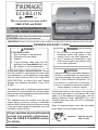
1
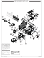
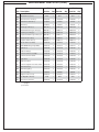
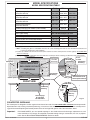
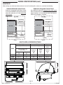
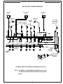
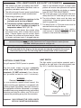
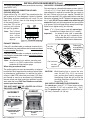
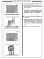
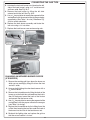
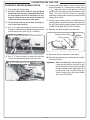
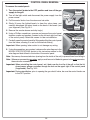
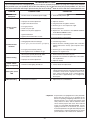
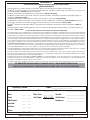
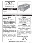
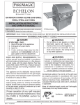
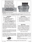
ECHELON
diamond “A” series
OUTDOOR BUILT-IN GAS GRILL
E660i, E790i, and E1060i
INSTALLATION INSTRUCTIONS
AND OWNER’S MANUAL
INSTALLER: Leave these instructions with consumer.
CONSUMER: Retain for future reference.
E790i shown
IMPORTANT: READ THESE INSTRUCTIONS CAREFULLY BEFORE STARTING INSTALLATION OR USE.
WARNINGS AND SAFETY CODES
DANGER:
IF YOU SMELL GAS:
1.
2.
3.
4.
WARNING:
1. Do not store or use gasoline or other
flammable vapors and liquids in the
vicinity of this or any other appliance.
2. An LP cylinder not connected for use
shall not be stored in the vicinity of this
or any other appliance.
Shut off the gas to the appliance.
Extinguish any open flame.
Open lid.
If odor continues, keep away from the
appliance and immediately call your
gas supplier or the fire department.
WARNING:
CODE AND SUPPLY REQUIREMENTS: This grill
must be installed in accordance with local codes
and ordinances, or, in the absence of local codes,
with the latest National Fuel Gas Code (ANSI
Z223.1/NFPA 54), or Natural Gas and Propane
Storage and Handling Installation Code (CSAB149.1).
Improper installation, adjustment, alteration,
service, or maintenance can cause injury
or property damage. For proper installation,
refer to the installation instructions. For
assistance or additional information,
consult a qualified professional installer,
service agency, or the gas supplier.
This appliance and its dedicated manual shutoff
valve must be disconnected from the gas-supply
piping system when testing the system at pressures
in excess of ½ psig (3.5 kPa).
All electrical outlets in the vicinity of the grill must
be properly grounded in accordance with local
codes, or, in the absence of local codes, with the
National Electrical Code, ANSI/NFPA 70, or the
Canadian Electrical Code, CSA C22.1, whichever
is applicable.
This appliance must be isolated from the gassupply piping system by closing its dedicated
manual shutoff valve during any pressure testing
of the gas-supply system at pressures up to and
including ½ psig (3.5 kPa).
Keep all electrical-supply cords and fuel-supply
hoses away from any heated surface.
Proper operation of your grill requires
prompt and periodic maintenance.
See the CARE & CLEANING section
for details.
Certified to:
ANSI Z21.58b-2012
CSA 1.6b-2012
10-32
Robert H. Peterson Co. • 14724 East Proctor Avenue • City of Industry, CA 91746
REV 2 - 1412081510
1
L-C2-402
INSTALLATION INSTRUCTIONS ET MANUEL DU PROPRIÉTAIRE
GRIL EXTÉRIEUR D’ÎLE DE GAZ D’ÉCHELON
IMPORTANT: LISEZ CES INSTRUCTIONS SOIGNEUSEMENT AVANT DE COMMENCER L’INSTALLATION OU L’UTILISATION
SÛRETÉ ET CODES D’AVERTISSEMENT
DANGER:
AVERTISSEMENT:
SI VOUS SENTEZ LE GAZ :
1. Coupez le gaz à l’appareil.
2. Éteignez-vous n’importe quelle flamme nue.
3. Ouvrez le couvercle si équipé d’un four.
4. Si l’odeur continue, gardez loin de
l’appareil et appelez immédiatement
votre département de fournisseur ou de
feu de gaz.
1. Ne stockez pas ou n’employez pas
l’essence ou d’autres vapeurs et liquides
inflammables à proximité de ceci ou
d’aucun autre appareil.
2. Un cylindre de propane non relié pour
l’usage ne sera pas stocké à proximité
de ceci ou d’aucun autre appareil.
CONDITIONS DE CODE ET D’APPROVISIONNEMENT:
Ce gril doit être installé selon des codes et des ordonnances
locaux, ou, en l’absence des codes locaux, avec l’un ou l’autre
le plus défunt Code national de gaz de carburant (norme ANSI
Z223.1/NFPA 54), et Stockage de gaz naturel et de propane
et manipulation du code d’installation (CSA-B149.1).
AVERTISSEMENT:
L’installation inexacte, l’ajustement, le
changement, le service, ou l’entretien
peuvent causer des dommages ou des
dégats matériels. Référez-vous à ce
manuel. Pour l’aide ou l’information
additionnelle, consultez un installateur
professionnel qualifié, l’agence de service,
ou le fournisseur de gaz.
Cet appareil et ses différents robinets d’isolement doivent être
démontés du gaz-fournissent le système sifflant en examinant
le système aux pressions au-dessus du ½ psig (kPa 3.5).
Cet appareil doit être isolé dans gaz-fournissent le système
sifflant par fermeture que ses différents robinets d’isolement
manuels pendant tous les essais sous pression du gazfournissent le système aux pressions jusques et y compris
le ½ psig (kPa 3.5).
•
Ce gril est pour ultilisation à l’extérieur seulement.
Si l’appareil est entreposé à l’intérieur, enlever les
bouteilles et les laisser à l’extérieur.
•
Ne pas ranger le gril immédiatement aprés l’avoir utilisé.
le laisser refroidir avant de le déplacer ou de la ranger.
Le non respect de cette mesure de sécurité pourrait
entraîner un incendie causant des dommages à la
propriété, des blessures ou la mort.
•
Ne pas utiliser cet appareil sous une surface
combustible.
•
Ne pas utiliser cet appareil sous un auvent. Le non
respect de cette mesure de sécurité pourrait entraîner
un incendie ou des blessures.
•
Dégagement minimal entre les parois latérales et
l’arriére de l’appareil et la construction combustible (45.7
cm à partir des parois latérales et 45.7cm à partir de
l’arriére).
•
•
Toutes les sorties électriques à proximité du gril doivent être
correctement fondues selon des codes locaux, ou en l’absence
de local code, avec le code électrique national, ANSI/NFPA
70, ou le code électrique canadien, CSA C22.1, celui qui est
applicable.
Maintenez tout électrique-fournissent des cordes et carburantfournissent des tuyaux partis de n’importe quelle surface de
chauffage.
RÉGULATEUR ADDITIONNEL DOIT ÊTRE INSTALLÉ
AVANT LE GRIL. VOIR LA SECTION DE CONDITIONS
D’OFFRE DE GAZ POUR LA PRESSION APPROPRIÉE
D’OFFRE DE GAZ.
Le régulareur de pression de gaz prévu avec cet appareil
de cuisson à gaz pour l’extérieur doit être utilisé. Ce
régulateur est réglé pour une pression de sortie de 5
pouces de colonne de l’eau pour le gaz naturel, et 10
pouces pour le propane.
•
Ne couvrez jamais la surface entière de cuisine ou de
gril de gauffreuses ou de casseroles. La surchauffe se
produira et les brûleurs ne seront pas très performants
quand la chaleur de combustion est emprisonnée audessous de la surface à cuire.
•
Ne pulvérisez jamais l’eau sur une unité chaude de gaz,
comme ceci peut endommager des composants de
porcelaine ou de fer de fonte.
•
Une fuite de GPL peut causer une incendie ou une
explosion si enflammée entraînant des blessures
corporelles graves ou la mort.
•
Communiquez avec le fournisseur de GPL pour les
réparations ou pour disposer de qules bouteille ou du
GPL non utilisé.
Certifié à la norme ANSI : Z21.58b-2012 / CSA 1.6b-2012
LE RÉGULATEUR INCLUS D’APPAREILS EST ÉVALUÉ
POUR LE MAXIMUM DE 1/2 (LIVRES PAR POUCE
CARRÉ). SI VOTRE OFFRE DE GAZ EST 1/2 PLUS
INSTALLATEUR : Laissez ces instructions avec le consommateur.
GRAND QUE (LIVRES PAR POUCE CARRÉ), UN
CONSOMMATEUR : Maintenez pour la future référence.
REV 2 - 1412081510
2
L-C2-402
CONTENTS
4
7
7
8
8
9
10
10
10
11
12
12
12
13
13
13
13
14
14
14
15
16
17
19
20
21
21
23
24
25
26
27
28
29
30
31
31
31
34
35
36
37
38
REPLACEMENT PARTS LIST
COUNTERTOP OVERHANG
MODEL SPECIFICATIONS
SUBSTRATE
BUILT-IN GRILL DIMENSIONS TABLE
BUILT-IN GRILL WIRING DIAGRAM
ELECTRICAL CONNECTIONS
GRILL MAINTENANCE AND SAFETY INFORMATION
LIGHT SWITCH
INSTALLATION REQUIREMENTS
ENSURE PROPER COMBUSTION AIR AND COOLING AIRFLOW
EXHAUST REMOVAL
GAS-SUPPLY PLUMBING REQUIREMENTS
NATURAL GAS INSTALLS
PROPANE GAS INSTALLS (HOUSEHOLD & CYLINDER)
WHEN A PROPANE CYLINDER IS USED
ENCLOSURE REQUIREMENTS
COUNTER PREPARATION
CONNECT THE GAS SUPPLY
INSTALLATION
INSTALL ZONE DIVIDERS
ELECTRICAL INSTALLATION
SAFE USE & MAINTENANCE OF PROPANE GAS CYLINDERS
IDENTIFICATION OF GRILL CONTROLS
OPTIONAL POWER HOOD
LIGHTING (IGNITION) INSTRUCTIONS
SHUTTING OFF THE UNIT
ROTISSERIE INSTRUCTIONS
OPTIONAL INFRARED BURNER OPERATION
GRILLING TIPS
ACCESSORIES
FIRE MAGIC® DRIP TRAY
CARE & CLEANING
REPLACING HALOGEN BULBS
POWER SUPPLY FUSE REPLACEMENT
REGULATOR CONVERSION
GAS ORIFICE CONVERSION
CONVERTING THE GAS TYPE
BURNER AIR SHUTTER ADJUSTMENT
CONTROL PANEL REMOVAL
NOTES PAGE
TROUBLESHOOTING
WARRANTY
REV 2 - 1412081510
3
L-C2-402
REPLACEMENT PARTS LIST
1
10
2
4
10
15
6
5
3
11
17
12
16
9
14
13
9
22
7
43
21
23
19
52
20
24
27
25
46
39
50
18
28
29
45
Some items shown
are optional, or are
n o t ava i l a bl e fo r
certain models. Your
model may vary, refer
to parts list.
To order replacement
par ts, contact your
local Fire Magic®
dealer.
REV 2 - 1412081510
44
Fig. 4-1
Items in light gray are
not available on all
models.
4
L-C2-402
REPLACEMENT PARTS LIST (Cont.)
E660i
Item Description
Part No.
E790i
Qty. Part No.
E1060i
Qty.
Part No.
Qty.
1.
Stainless cooking grid (set of 2 or 3)
3544-S-3
1
3539-S-3
1
23539-S-2
2
2.
Flavor grid (set of 3 or 4)
3057-S-3
1
3056-S-3
1
3056-S-4
1
3.
Main burner
3041-50
3
3041-50
3
3041-50
4
4.
Heatshield kit
24177-05
3
24177-05
3
24177-05
4
5.
Silicone gasket
24177-06
3
24177-06
3
24177-06
4
6.
Infrared burner *
3050
1
3050
1
3050
1
7.
Oven lid
24193-55
1
24188-55
1
24183-55
1
or
Oven lid w/ window
24193-54
1
24188-54
1
24183-54
1
8.
Window (only) *‡
24187-45
1
24187-45
1
24187-45
1
9.
Warming rack
36735-M
1
36755-M
1
36745-M
1
10.
Back burner assembly
24794-02
1
24789-02
1
24784-02R/L
1
11.
Back burner cover
24794-010
1
24789-010
1
24784-010
2
12.
Zone separator
13.
Heavy-duty rotisserie motor
14.
3061-S
2
3061-S
2
3061-S
3
3600-05M
1
3600-05M
1
3600-05M
1
Heavy-duty rod
3606-40
1
3609-40
1
3607-40
1
15.
Heavy-duty rod knob
24187-16
1
24187-16
1
24187-16
1
16.
Meat holder (pair)
3613
1
3613
1
3613
1
17.
Counterbalance
3620E
1
3620E
1
3620E
1
18.
Grid lifter
3519
1
3519
1
3519
1
19.
Convertible regulator
PR-4
1
PR-4
1
PR-4
1
20.
Valve manifold w/ back burner
24193-22
1
24188-22
1
24183-22
1
21.
Control panel w/ back burner, raceway, and
wire harness †
24194-15
1
24189-15
1
24184-15
1
22.
Small knob
24182-42
1
24182-42
1
24182-42
2
23.
Large knob
24182-41
3
24182-41
3
24182-41
4
24.
LED disk (small)
24182-64
1
24182-64
1
24182-64
2
25.
LED disk (large)
24182-63
3
24182-63
3
24182-63
4
26.
or
Oven hood thermometer ‡
23305
1
23305
1
23305
1
Grill top thermometer (window models) ‡
3573
1
3573
1
3573
1
27.
Power supply w/ connector †
24187-18
1
24187-18
1
24187-18
1
* If equipped
‡ Not shown
† Add (M) to part number for power hood
REV 2 - 1412081510
5
L-C2-402
REPLACEMENT PARTS LIST (Cont.)
E660i
Item Description
Part No.
E790i
Qty. Part No.
E1060i
Qty.
Part No.
Qty.
28.
Drip tray
3087
1
3087
1
3087
1
29.
Drip tray liner (set of 4)
3557
1
3557
1
3557
1
30.
Wire harness for raceway ‡
24194-26
1
24189-26
1
24184-26
1
31.
Back burner electrode *‡
4199-52
1
4199-52
1
4199-52
2
32.
Electrode ‡
3199-72
3
3199-72
3
3199-72
4
33.
Natural gas orifice(s) ‡
3001-42-3
1
3001-38-3
1
3001-40-4
1
34.
Natural back burner gas orifice(s) ‡
3001-53-1
1
3001-51-1
1
3001-53-2
1
35.
Propane gas orifice(s) ‡
3001-54-3
1
3001-53-3
1
3001-53-4
1
36.
Propane back burner gas orifice(s) ‡
3001-63-1
1
3001-57-1
1
3001-63-2
1
37.
Natural smoker orifice ‡
3003-68-1
1
3003-68-1
1
3003-68-1
1
38.
Propane smoker orifice ‡
3003-77-1
1
3003-77-1
1
3003-77-1
1
39.
Smoker drawer assembly
24182-45
1
24182-45
1
24182-45
1
40.
12V / 10 watt halogen light bulb ‡
24187-15
2
24187-15
2
24187-15
3
41.
Light lens ‡
24187-26
2
24187-26
2
24187-26
3
42.
Lamp assembly ‡
24187-28
2
24187-28
2
24187-28
3
43.
Power hood motor assembly *
24183-18
1
24183-18
1
24183-18
1
44.
Power hood rocker switch*
24187-39
1
24187-39
1
24187-39
1
45.
Light switch
24182-46
1
24182-46
1
24182-46
1
46.
Light microswitch
24187-20
1
24187-20
1
24187-20
1
or
Power hood light & motor microswitch
24187-44
1
24187-44
1
24187-44
1
47.
Flash tube (left) ‡
24187-29
1
24187-29
1
24187-29
1
48.
Flash tube (right) ‡
24187-35
2
24187-35
2
24187-35
3
49.
Flex connector ‡
3030-08
1
3030-08
1
3030-08
1
50.
Support screw (set of 2)
24182-47
1
24182-47
1
24182-47
1
51.
Fire Magic® cookbook ‡
3595
1
3595
1
3595
1
52.
Wire harness extension
24182-53
1
24182-53
1
24182-53
1
* If equipped
‡ Not shown
REV 2 - 1412081510
6
L-C2-402
MODEL SPECIFICATIONS
MODEL SPECIFICATIONS TABLE
Table 1
Main burner quantity
N/P orifice drill size
Back burner quantity
N/P orifice drill size
Smoker drawer burner
N/P orifice drill size
Infrared searing burner
N/P orifice drill size
E660i
3
#42 / #54
1
#53 / #63
E790i
3
#38 / #53
1
#51 / #57
E1060i
4
#40 / #53
2
#53 / #63
#68 / #77
#68 / #77
#68 / #77
#45 / #55
#45 / #55
#45 / #55
3176-50
3186-50
3185-50
▲
Echelon insulating liner model # (not included)*
120VAC / 1.5A / 60 Hz
Power Supply Rating
12V / 10 watt halogen light bulb
Oven Lights Rating
A Countertop to unit bottom cut-out*
12"
12"
12"
B Side to side non-combustible cut-out*
31-1/4"
37"
50"
C Front to back non-combustible cut-out*†
23-1/2"
23-1/2"
23-1/2"
33"
38-3/4"
51-3/4"
D Control panel width non-combustible cut-out‡
▲
If equipped
* Note: If installing this grill in a combustible enclosure, the correct insulating liner must be used. Consult liner instructions for
counter cut-out dimensions and installation.
† Includes any substrate at front wall of enclosure (in the area the rear of the control panel is to sit flush against). See SUBSTRATE
section on next page.
‡ Only applicable for non-combustible enclosures that have countertops with an overhang (see illustration and section below).
TOP VIEW
Extra cut-out
for Power
Hood only!
B
Countertop
TOP VIEW
(Countertop)
NON-COMBUSTIBLE
C
ENCLOSURE CUT-OUT
1-1/4" x 10"
Y (Overhang)
(Control
panel)
DIMENSIONS
11"
Lower support
Control panel
X
X= 7/8"
Y= Total
Countertop
Overhang
Countertop
overhang
1/
4"
Clearance
D
Check clearance for
control panel removal
FRONT VIEW
SIDE VIEW
A
Countertop
overhang
Control
panel
Countertop
overhang
See next page
for substrate
considerations
Fig. 7-1
COUNTERTOP OVERHANG
The control panel is designed to sit flush against the enclosure front wall. If the non-combustible enclosure countertop extends
beyond the front wall, creating a countertop overhang, it must be cut flush with the front wall for the width of the control panel or
a gap will be created exposing the forward portions of the left and right side grill fire walls. See illustrations above.
Important:
REV 2 - 1412081510
FOR YOUR SAFETY, you must provide openings in the island enclosure for drainage, replacement air, and
cross-ventilation of any storage area exposed to possible leakage from gas connections, the unit, or propane
tanks. See the ENCLOSURE REQUIREMENTS section for details.
7
L-C2-402
MODEL SPECIFICATIONS (cont.)
SUBSTRATE
When adding any substrate to the enclosure front wall (including tiles, stone, etc.), consider the following:
Substrate Behind Control Panel
Substrate Alongside Control Panel
Substrate + countertop "front to back" cutout
must equate to Dim. C (see previous page)
when the substrate sits flush behind the
control panel.
Any additional substrate alongside the control panel
does not need to be considered in Dim. C (see previous
page), however a 1/4" clearance on each side (same as
overhang) and below is required.
TOP VIEW
TOP VIEW
C
Grill liner
(Countertop)
(Countertop)
Substrate
(includes tiles,
etc. at front of
enclosure)
Substrate
(includes tiles,
etc. at front of
enclosure)
Flush
Flush
(Control panel)
C
Grill liner
(Control panel)
Countertop
overhang
1/ " (if applicable)
4
Clearance
Countertop
overhang
(if applicable)
1/
4"
Clearance
Fig. 8-1
Fig. 8-2
BUILT-IN GRILL DIMENSIONS TABLE
Model
Height
Width
Depth
(Top to bottom)
(Left to right)
(Front to
back)
Upper hanger to top
(with oven)
Hanger to
hanger
(G)
Control
panel
width
(H)
Maximum
depth
(I)
Open
(E)
Closed
(F)
E660i
23-5/8"
15"
36-1/4"
32-1/2"
29-3/4"
E790i
23-5/8"
15"
42"
38-1/4"
29-3/4"
E1060i
23-5/8"
15"
54-7/8"
51-1/4"
29-3/4"
G
I
F
E
H
REV 2 - 1412081510
Fig. 8-3
8
L-C2-402
MODEL SPECIFICATIONS (cont.)
BUILT-IN GRILL WIRING DIAGRAM*
Center oven
light
Left oven
light
Backburner
igniter
Main burner igniters
Right oven
light
Smoker
igniter
Backburner
igniter
Oven light
micro switch
(not used for
Magic View)
Wire harness
assembly
Light
switch
Valve
manifold
Main
Back
burner burner 4
Main
burner 3
Main Smoker Main
burner 2 burner burner 1
Back
burner
Ground
Wire
LED disc
(large)
For Magic
View only
LED disc
(small)
Wire harness
extension
Power supply
* E1060i model shown. Model wire diagrams may vary.
Note: In addition, a wire diagram specific to your unit
can be found affixed to the inside of the control
panel.
REV 2 - 1412081510
9
L-C2-402
GRILL MAINTENANCE AND SAFETY INFORMATION
1. The outdoor grill and surrounding area MUST
remain clear of flammable substances such as
gasoline, yard debris, wood, etc.
2. The airflow through the vent space located below
the control panel must remain unobstructed.
5.
3. When using propane gas:
a. The required ventilation openings in the 6.
enclosure must be clear of debris.
lead to a fire beneath the grill. A proper flame
pattern will ensure safe operation and optimal
performance. Adjust the air shutter as needed
(see AIR SHUTTER ADJUSTMENT).
The in-line gas valve or gas cylinder valve must
always be shut OFF when the grill is not in use.
The drip collector holes must be clear and
unobstructed. Excessive grease deposits can
result in a grease fire.
b. The propane cylinder, regulator, and rubber
hose must be in a location not subject to 7. The back burner or IR burner cover must be
removed before using the burner.
temperature above 125° F (51° C).
4. The flames on each burner burn evenly along 8. Whenever reconnecting any wires, apply a
small amount of dielectric grease to the male
the entire burner with a steady flame (mostly
connector, then make the connection.
blue). If burner flames are not normal, check
and clean the orifice and burner/venturi tubes
for insects and insect nests. A clogged tube can
WARNING: NEVER cover the entire cooking or grill surface with griddles or pans. Overheating will occur, and
burners will not perform properly when combustion heat is trapped below the cooking surface.
CAUTION: NEVER spray water on a hot gas unit.
The grill serial identification number is located on the underside of the drip tray handle. It
is recommended that the drip tray first be removed and cleaned / emptied of its contents,
then turned over to view. The unit rating label is located inside of the control panel.
LIGHT SWITCH
ELECTRICAL CONNECTIONS
The light switch is push button operated, and is
located on the right side of the control panel (see
Fig. 10-1). It controls the power to all lights.
This grill requires 120VAC power to operate.
Plug the power supply cord into a properly
wired and inspected GFCI electrical
receptacle (15 AMP minimum). Use a heavyduty grounded extension cord if necessary.
WARNING
Electrical Grounding Instructions
For your protection against shock hazard, this
outdoor-cooking gas-appliance is equipped with
a three-pronged (grounding) electrical connector.
This appliance should be connected to a properly
grounded three-prong receptacle using a grounding
extension cord rated for outdoor use. Do not cut or
remove the grounding prong from the connector.
Light
switch
Fig. 10-1
Important: ONLY REPLACE THE OVEN LIGHTS
WITH 12V / 10 WATT HALOGEN BULB(S).
REV 2 - 1412081510
10
L-C2-402
INSTALLATION REQUIREMENTS
Installation must be performed by a qualified professional service
technician.
This grill is designed for outdoor use only. DO NOT use this grill inside
a building, garage, enclosed area, or under an unprotected overhead
combustible construction.
See below and the EXHAUST REMOVAL section on the following
page for details on installing under overhead construction.
DO NOT use this grill in or on a recreational vehicle or boat.
Important: If installing this grill in a combustible surround, the correct
RHP insulating liner must be used.
Important: Refer to the information below to ensure all required
clearances are met.
The grill must have a minimum clearance of 18" from combustible
materials/items AT ALL TIMES.
Min.
6'
Combustible construction:
Requires vent hood or protection kit
Non-combustible construction:
Okay as-is
Fig. 11-1 Overhead requirements
Non-combustible
Min.
4"
Overhead Construction Requirements (if applicable)
Non-combustible overhead construction: A 6 foot clearance is required
between the countertop and the construction above (Fig. 11-1).
Combustible overhead construction: A 6 foot clearance is required
between the countertop and the construction above. A vent hood
(see EXHAUST REMOVAL section) or an RHP combustible overhead
protection kit is required directly above the grill. See Fig. 11-1. RHP
vent hoods and protection kits are available, contact your local
dealer.
Side and Rear Wall Clearances
For the minimum clearances between the grill and any side or rear
walls, your setup must fall within one (or more) of the following:
A. Clearance between grill and strictly non-combustible wall
(i.e. brick wall, see Fig. 11-2)
• The grill must have a minimum of 4" right, left, and rear
clearance from any non-combustible wall.
(To allow for proper ventilation and prevent dangerous
overheating.)
(Clearance required for
right, left, and rear)
Fig. 11-2 Clearance 'A' Diagram
Non-combustible
substrate
Non-combustible 4"
Min.
14"
Fig. 11-3 Clearance 'B' Diagram
Combustible
B. Clearance between grill and a protected combustible wall
(i.e. a non-combustible wall in front of a combustible wall to serve
as a barrier. This can be accomplished by brick, or a metal stud
finished with non-combustible substrate, see Fig. 11-3)
• The grill must have a minimum of 14" right, left, and rear
clearance from the protected combustible wall.
(The 4" non-combustible material plus an additional 10"
clearance between the grill and protected wall.)
C. Clearance between grill and combustible wall
• The grill must have a minimum of 18" right, left, and rear
clearance from any combustible wall (see Fig. 11-4).
Backsplash Clearance (if applicable)
If a non-combustible backsplash exists, it must have a minimum of a
4" clearance from the rear of the grill (to allow for proper ventilation
and prevent dangerous overheating). See Fig. 11-5.
Combustible
(Clearance required for
right, left, and rear)
Min.
18"
(Clearance required for
right, left, and rear)
Fig. 11-4 Clearance 'C' Diagram
Non-combustible
Backsplash
Min.
4"
Important: This 4" backsplash clearance must first be met prior to
any non-combustible walls beginning behind it.
Fig. 11-5 Backsplash clearance
REV 2 - 1412081510
11
L-C2-402
INSTALLATION REQUIREMENTS (Cont.)
The control panel MUST remain removable for servicing
(see PARTS LIST).
ENSURE PROPER COMBUSTION AIR AND
COOLING AIRFLOW
Proper airflow (Fig. 12-1) MUST be maintained for the
grill to perform as it was designed. If airflow is blocked,
overheating and poor combustion will result. Do not
block the 1" (2.5 cm) front air inlet along the bottom
of the control panel or
more than 75% of the
cooking grid surface
with pans or griddles.
Note: The 1" (2.5 cm)
front air space
also allows
access to the
drip tray.
GAS-SUPPLY PLUMBING REQUIREMENTS
For natural gas or a household propane system, rigid 1/2"
(1.3 cm) or 3/4" (1.9 cm) black steel pipe or local codeapproved pipe is required to conduct the gas supply to
the unit. Contact your local gas supplier. Connect this
pipe to the required C.S.A.-approved stainless-steel flex
connector (attached). An NPT adapter has been provided
for 1/2" pipe. DO NOT use a rubber hose within the grill
enclosure. Apply only joint compounds that are resistant
to all gasses to all male pipe fittings except flare fittings.
Make sure to tighten every joint securely.
Note: If 1/2" (1.3 cm) pipe is used with natural gas,
it should be no longer than 20' (6.1 meters).
Important:
Fig. 12-1 - Ventilation diagram
An external valve (with a removable
key) in the gas line is necessary for
safety when the grill is not in use. It also
provides for convenient maintenance.
EXHAUST REMOVAL
If the grill is installed under an overhead structure that is
constructed of non-combustible material: an exhaust hood
is recommended. See below.
Left-side
hanger
If the grill is installed under an overhead structure that is
constructed of combustible material: an exhaust hood is
required. See below.
Note: An alternative to an exhaust removing vent
hood is an RHP combustible overhead
protection kit. See previous page.
Flex connector
Left-side
support wall
When using an exhaust hood:
The cooking grid area must be covered by an exhaust
hood (with a vent) larger than the cooking surface. Refer
to manufacturer specifications. An exhaust fan with a
rating of 1,000 CFM (cubic feet per minute) (472 liters
per second) or more may be necessary to effectively
remove smoke and other cooking by-products from the
area under the hood. RHP Vent Hoods are available,
contact your local dealer.
Fig. 12-4
CAUTION: Wind blowing into or across the rear
oven lid vent (Fig. 12-2) can cause
poor performance and/or dangerous
overheating. Orient the grill so that the
prevailing wind blows toward the front of
the grill (Fig. 12-3).
GAS SUPPLY AND MANIFOLD PRESSURES:
For natural gas - normal 7" (17.78 cm) water column
(w.c.), minimum 5" (12.7 cm), maximum 10 1/2" (26.7
cm). For propane gas - normal 11" w.c., minimum 10"
(25.4 cm), maximum 13" (33 cm).
THIS UNIT MUST NOT BE LOCATED IN A FULLY
ENCLOSED AREA OF ANY KIND.
INCORRECT
Orient grill
so prevailing
wind blows
this way.
CORRECT
Rear oven lid vent
YOU MUST PROTECT
REAR OVEN VENT FROM
PREVAILING WIND
Fig. 12-2
REV 2 - 1412081510
PLACE GRILL SO PREVAILING
WIND BLOWS TOWARD FRONT
OF GRILL
Fig. 12-3
12
L-C2-402
ENCLOSURE REQUIREMENTS
FOR YOUR SAFETY, you must provide the openings listed
below for drainage, replacement air, and cross-ventilation
of any storage area exposed to possible leakage from gas
connections, the unit, or propane cylinders.
One side of the enclosure can be left completely open to
the outside, OR 4 ventilation openings must be created:
Nat. gas
installs
L.P. gas
installs
(repeat for
opposite
side)
(repeat for
opposite
side)
NATURAL GAS INSTALLS
Two of the openings are to be at the top level (approx.
4" below the countertop) and on opposite walls of the
enclosure. 2 more openings must be at the floor level (no
more than 5" above the floor) and on opposite sides of the
enclosure. Each opening must have a minimum of 10 sq.
in. of free area. To achieve the proper ventilation, you may
drill a series of holes, omit the grout from masonry joints,
or replace a brick with a hardware cloth screen. If the floor
in the cabinet is raised and the space beneath the cabinet
is open to the outside, the lower ventilation openings may
be in the floor. Reference Fig. 13-1.
Fig. 13-1 Ventilation detail
Grill
PROPANE GAS INSTALLS
(HOUSEHOLD & CYLINDER)
Heatshield
Two of the openings are to be at the cylinder valve level
(approx. 16" above the floor) and on opposite walls of the
enclosure. 2 more openings must be at the floor level (no
more than 5" above the floor) and on opposite sides of the
enclosure. Each opening must have a minimum of 10 sq.
in. of free area. To achieve the proper ventilation, you may
drill a series of holes, omit the grout from masonry joints,
or replace a brick with a hardware cloth screen. If the floor
in the cabinet is raised and the space beneath the cabinet
is open to the outside, the lower ventilation openings may
be in the floor. Reference Fig. 13-1.
C.S.A. listed
stainless steel
flex connector
Adapter
L.P.
cylinder
Regulator/
hose
assembly
Fig. 13-2 Propane cylinder orientation
Cylinder & regulator/
hose assembly
protected by heatshield
WHEN A PROPANE CYLINDER IS USED
When a propane cylinder is installed inside of the enclosure,
the guidelines below MUST be followed. FAILURE TO
DO SO MAY CAUSE DAMAGE TO YOUR UNIT AND/OR
PERSONAL INJURY. Reference Fig. 13-2 for an example.
• Only a C.S.A. listed stainless steel connector can be
connected to the grill.
• The regulator/hose assembly coming from the propane
cylinder can only be connected to the above mentioned
grill flex connector. DO NOT connect the regulator/
hose assembly directly to the grill. An adapter will
be required.
Equipped with
adapter for hose
assembly and
flex connector
Fig. 13-3 Optional RHP door w/tank tray
• A heatshield must be installed to protect the regulator/
hose assembly and propane cylinder valve.
• RHP offers a propane cylinder door with tank tray
to meet the cylinder install requirements. See Fig.
13-3.
REV 2 - 1412081510
13
L-C2-402
INSTALLATION
Note: When a propane cylinder is installed inside
of the enclosure, the guidelines found in the
ENCLOSURE REQUIREMENTS section
MUST be followed.
COUNTER PREPARATION
Consult Table 1 for non-combustible enclosure cut-out
dimensions. An RHP insulating liner must be used if
any supporting construction is combustible. Consult the
instructions that come with the liner for dimensions and
additional installation information before beginning the
installation.
This outdoor built-in grill must be supported by the
stainless-steel hanger extending from the upper portion
of the grill. The hanger rests on the left, right, and back
of the countertop and on the two front structural supports
with attached adjustable screws located below the control
panel on the left and right sides (see Fig. 14-3).
For household propane or natural gas units:
CAUTION: Use only C.S.A. listed stainless-steel flex
connectors within the enclosure.
WARNING
A rubber or plastic connector will rupture or leak,
resulting in an explosion or serious injury if used
inside the appliance enclosure.
1. Run the attached flex connector routed under the
left side of the grill out of the enclosure and to the
gas stub.
The control panel is designed to sit flush against the
enclosure front wall (see Fig. 14-2). If the non-combustible
enclosure countertop extends beyond the front wall,
creating a countertop overhang (see Fig. 14-1), it must
be cut flush with the front wall for the width of the control
panel or a gap will be created exposing the forward
portions of the left and right side grill fire walls. Reference
the MODEL SPECIFICATIONS section.
2. Turn OFF the gas supply at the source. Remove
the 1/2" adapter that is loosely connected to the flex
connector. Attach the adapter to the gas-supply stub
using a pipe joint compound that is resistant to all
gasses. Tighten securely. Then attach the open end
of the flex connector to the adapter. Tighten securely.
Note: It is not necessary to remove the control panel
or knobs to install this unit.
3. Turn all burner control knobs to the OFF position.
Turn the gas supply on. Then carefully check all gas
connections for leaks with a brush and half-soap/
half-water solution before lighting. NEVER USE A
MATCH OR OPEN FLAME TO TEST FOR LEAKS.
CONNECT THE GAS SUPPLY
For propane cylinders:
For connecting a propane unit to a portable propane tank,
read the safety warnings and follow the instructions in the
section SAFE USE AND MAINTENANCE OF PROPANE
GAS CYLINDERS.
4. Close the dedicated gas-supply shut-off valve, then
slide the grill into place. Do not to pinch, kink, or
damage the gas connector line.
5. Rotate the adjustable support screws to the left to
raise and to the right to lower the respective side
of the appliance grill. Use a 7/16" open-end wrench
as needed.
control panel
stops here
Countertop
Proposed cutout in overhang
GAP CREATED
Fig. 14-1
Countertop
Important:
Overhang
Do not extend the support screws so
far that any part of the hanger is raised
off the counter top.
IDEAL
Flush-mounted
control panel
To gas
system
Fig. 14-2
OFF
(Countertop)
Adjustable
support
screw
Flex
connector
Dedicated manual shut-off valve
Gas inlet pipe
Pipe
adapter
fitting
(Cut-out)
Hanger
Bottom of
face
REV 2 - 1412081510
Bottom
of cut-out
opening
Fig. 14-3