1
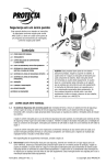
Torit Installation
and Operation Manual
®
FOR TORIT FILTER CARTRIDGE SYSTEM DUST COLLECTORS
Torit Downflo® Models SDF–2, SDF–4, SDF–6
Includes Installation, Operation, and Service Instructions
WITH QUICK-CHANGE
ULTRA-WEB® II
FIBRA-WEB®
ULTRA-TEK®
FILTER ELEMENTS
IMPORTANT
This manual contains specific precautionary statements relative to worker
safety in appropriate sections. Read this manual thoroughly and comply as
directed. It is impossible to list all of the potential hazards of dust control
equipment. It is imperative that use of the equipment be discussed with a Torit
representative. Personnel involved with the equipment or systems should be
instructed to conduct themselves in a safe manner.
Donaldson Company, Inc. © 1995
1
IOM-46740-00
Revision 5
NOTE
CAUTION
Statements indicate precautions necessary
to avoid potential equipment failure.
Statements indicate potential safety hazards.
CAUTION
Application of Dust Control Equipment:
• Special care must be exercised in the use of
dust collection equipment when combustible
equipment, such as buffing lint paper, wood
dust, aluminum, and magnesium are present.
These materials may present a fire or
explosion hazard. A prudent user of Torit
equipment should consult and must comply
with all National and Local Fire Codes and/
or other appropriate codes when determining
the location and operation of dust collection
equipment.
•
• Under no conditions should anyone, including
the machine operator, be allowed to put
burning objects or lit cigarettes into the hood
or ducting of any dust control system.
• Avoid mixing combustible materials with
dust generated from grinding of ferrous
metals due to the potential fire hazard caused
by sparks being pulled into the dust collection
equipment.
• When collection equipment is used to collect
flammable or explosive dusts, the dust
collection equipment should be located
outside the building. Also, an installer of
fire extinguishing equipment, familiar with
this type of fire hazard and local fire codes,
should be consulted for recommendations
and installation of the proper fire
extinguishing equipment. Torit equipment
does NOT contain fire extinguishing
equipment.
Explosion relief vents are required on some
applications. Consult with an insurance
underwriter or a NFPA Manual to
determine proper vent sizing requirements.
Vents installed on dust collection equipment
within a building must relieve to the outside
of the building to minimize chances of a
secondary explosion. Consult the proper
authority to determine proper method of
venting the dust collection equipment. Torit
equipment does NOT contain explosion
relief vents, except on special order.
• To insure optimum collector performance,
always use Torit-Built® replacement
filters.
TORIT PRODUCTS is the leading designer and
manufacturer of dust collector systems for the
control of industrial air pollution. Its systems are
designed to help reduce occupational hazards,
lengthen machine life, reduce in-plant maintenance
requirements, and improve product quality.
2
Donaldson Company, Inc. © 1995
Table of Contents
Notes and Cautions ............................. 2
Data Sheet ........................................... 3
Figures ................................................. 4
1.0
Introduction ......................................... 6
1.1
Operational Explanation ..................... 6
1.1.1 Normal Operation ............................... 6
1.1.2 Filter Cleaning ..................................... 7
2.0
Installation ........................................... 7
2.1
Inspection ............................................. 7
2.2
Ship Loose Items .................................. 7
2.3
Equipment/Tools Required ................... 7
2.4
Assembly of Standard Equipment ........ 7
2.5
Assembly of Optional Equipment ........ 8
2.5.1 Compressed Air Inlet Adapter ............. 8
2.5.2 Leg Levelers ......................................... 8
2.5.3 Inlet Collar ........................................... 8
2.5.4 Adapter to Round Outlet ..................... 8
2.5.5 Adapter Auto-Lok™/Ultra-Lok™ ....... 8
2.5.6 Adapter HEPA/Activated Carbon ...... 12
2.5.7 Leg Pack SDF ..................................... 12
2.5.8 55-Gallon Drum Pack ......................... 14
2.5.9 5-Gallon Pail Pack .............................. 14
2.5.10 Bin Vent Base Pack ............................. 14
2.5.11 Flex-Trunk™ Assembly
7-Foot/10-Foot SDF ............................ 16
2.5.12 Weather Hood Pack ........................... 16
2.5.13 Explosion Vent Pack ........................... 16
2.5.14 Explosion Vent Cabinet ...................... 20
Data Sheet
2.6
Electrical Installation ............. 20-23,29-30
2.6.1 Electrical Operation ............................ 30
2.6.2 Checker™ Board, Diagnostics and
Control Panel Specifications ............... 30
2.6.3 Solid State Control Timer
Specifications ................................... 30-31
2.6.4 Magnehelic®* Gage ............................ 31
2.6.5 Torit ∆P Control .............................. 33-35
2.6.6 Photohelic®* Gage .............................. 37
2.7
Compressed Air Supply Installation.... 38
2.7.1 Air Manifold Assembly ....................... 39
2.7.2 Blower Compartment ......................... 39
2.7.3 Dust Storage Compartment ................ 39
4.0
Start-up ............................................... 39
5.0
Operating Adjustment ........................ 40
5.1
Checker Board .................................... 40
5.2
Solid State Control Timer ................... 40
5.3
∆P Control Calibration ....................... 41
5.4
Outlet Damper Adjustment ................. 41
5.5
Operating Checks ............................... 41
6.0
Service ................................................ 42
6.1
Filter Element Removal ...................... 42
6.2
Filter Element Installation ................... 42
6.3
Bag-Out Filter Element Removal ..... 42-43
6.4
Dust Removal Dust Container ........ 43-44
6.4.1 Dust Removal—Hopper Model .......... 44
6.5
Compressed Air Components ............. 45
6.6
Electrical Service ................................ 45
7.0
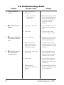
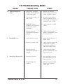
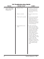
Troubleshooting Guide .................... 46-52
Parts Ordering Information ................ 54
Warranty ............................................ 54
* Magnehelic and Photohelic are registered trademarks
of Dwyer® Instruments, Inc..
Customer Name
Address
Shipping Date
Installation Date
Model Number
Serial Number
Filter Medium
Accessories
Other
Donaldson Company, Inc. © 1995
3
Figures
Figure
Figure
Figure
Figure
Figure
Figure
1
2
3
4
5
6
–
–
–
–
–
–
Figure 7
–
Figure 8
–
Figure 9 –
Figure 10 –
Figure 11 –
Figure 12 –
Figure 13 –
Figure 14 –
Figure 15 –
Figure 16 –
Figure 17 –
Figure 18 –
Figure 19 –
Figure 20 –
Figure 21 –
Figure 22 –
Figure 23 –
Figure 24 –
Figure 25 –
4
SDF-4 Phantom View .............. 5
Operational Schematic ............ 6
Compressed Air Inlet Adapter 8
Leg Levelers ............................ 8
Inlet Collar .............................. 9
Adapter Pack to
Round Outlet .......................... 9
Adapter Pack
Auto-Lok/Ultra Lok ................ 10
Adapter Pack HEPA/
Activated Carbon .................... 11
Leg Pack SDF .......................... 12
55-Gallon Drum Pack &
5-Gallon Pail Pack................... 13
Bin Vent Base Pack ................. 14
Flex-Trunk Assembly
7-Foot/10-Foot SDF ................. 15
Weatherhood Pack .................. 17
Explosion Vent Pack ............... 18
SDF-4 with Explosion Vents—
Phantom View ......................... 19
Prewired with Checker Board
on Unit .................................... 21
Unwired with Checker Board
on Unit .................................... 21
Prewired with Checker Board
in Remote Enclosure ............... 22
Unwired with Checker Board
in Remote Enclosure ............... 23
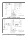
Wiring Diagram 575V 60Hz
3PH 3, 5, 7-1/2, 10 hp ............ 24
Wiring Diagram 380V 50Hz
3PH 3, 5 hp ............................. 24
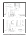
Wiring Diagram 380V 50Hz
3PH 7-1/2 hp ........................... 25
Wiring Diagram 230V 60Hz
3PH 3, 5, 7-1/2, 10 hp ............ 25
Wiring Diagram 200V 50/60Hz
3PH 3, 5 hp ............................. 26
Wiring Diagram 200V
50/60Hz 3PH 7-1/2, 10 hp ...... 26
Figure 26 – Wiring Diagram 460V 60Hz
3PH 3, 5, 7-1/2, 10 hp ............. 27
Figure 27 – Wiring Diagram 208 V
60Hz 3PH 3, 5, 7-1/2, 10 hp ... 27
Figure 28 – Remote Checker Board
Assembly ................................. 28
Figure 29 – SDF Solid-State Timer Wiring
Diagram .................................. 29
Figure 30 – Magnehelic Gage .................... 32
Figure 31 – Remote-Mounted Magnehelic
Gage ....................................... 32
Figure 32 – ∆P Control Display ................. 33
Figure 33 – Printed Circuit Board .............. 35
Figure 34 – Photohelic Gage ...................... 36
Figure 35 – Remote-Mounted Photohelic
Gage ....................................... 36
Figure 36 – Photohelic Gage
Wiring Diagram ...................... 37
Figure 37 – Air Manifold Assembly ........... 38
Figure 38 – Bag-Out Assembly .................. 43
Figure 39 – Bag-Out Filter Removal .......... 43
Figure 40 – Dust Container Support
System ..................................... 44
Figure 41 – Typical Electrical
Component Assembly ............. 45
Donaldson Company, Inc. © 1995
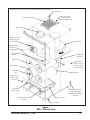
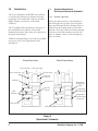
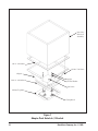
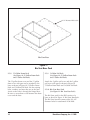
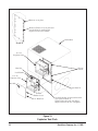
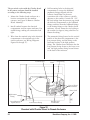
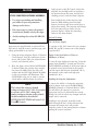
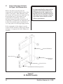
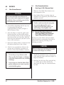
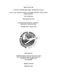
Sprinkler Taps (not shown) (not supplied standard with the SDF)
Lifting Eyes
Screwed-on Rear
Access Panel to
Blower Compartment
Outlet with Damper
Inlet Collar
Checker™ Board
Diagnostic and
Control Panel
Blower Pack
Hinged Access
to Electrical
Compartment
Tool Operated
Fastener
Air Manifold
Assembly
Filter Yoke
Screwed-on
Rear Access
Panel to Clean
Air Manifold
Filter Element
Filter Wing
Nut
Venturi
Hinged Access
Door to Dust
Container
T–Handle
Quick Latch
Lift Assembly Dust
Container
Compressed Air Inlet—
1/2 National Pipe
Threads or British Pipe
Threads
Dust Container
Legs or Casters
Figure 1
SDF–4 Phantom View
Donaldson Company, Inc. © 1995
5
1.0
Introduction
The Torit® Downflo® model SDF dust collector
is used for the collection of airborne dust and
particulate. The model SDF collector provides
highly efficient, continuous, on-line dust
collection.
The Torit-Built® filter elements are the heart of
the model SDF dust collector. These filter
elements help ensure that clean air is returned to
the plant environment.
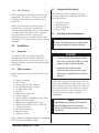
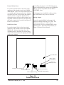
1.1
Operational Explanation
(See Figure 2 Operational Schematic)
1.1.1
Normal Operation
During normal operation, contaminated air
enters through the top inlet area and passes
down and through the filter elements. Dust is
collected on the outside surface of the filter
elements. The clean, filtered air flows through
the center of the filter elements and into the
clean air plenum, where it exits through the
clean air outlet.
Technical and field support are always available
from your local Torit representative and
distributors.
Filter Element Purge
Normal Operation
Dirty Air Inlet Clean Air Outlet
Dirty Air Plenum
Blower Pack
Silencer
Section
Deflector
Filter
Elements
Fan Outlet
Diaphragm
Cleaning Air
Valve
Clean Air
Plenum
Compressed
Air Manifold
Compressed
Air Inlet Fitting
(Purge Air)
Filter Section
Dirty Air Inlet
Figure 2
Operational Schematic
6
Donaldson Company, Inc. © 1995
1.1.2
Filter Cleaning
Filter elements are cleaned automatically and
sequentially. The result is that only one filter
cartridge will be off-line for cleaning at any
given time.
During the filter element cleaning purge, a
solenoid valve is energized, causing the
corresponding diaphragm valve to send a pulse
of compressed air through the filter element
(from the inside outward), removing the
collected dust from the outside surfaces of the
filter element. The dust falls into the dust storage
container.
2.0
Installation
2.1
Inspection
The Downflo SDF is normally shipped by
common carrier and should be checked for
damage that may have occurred en route. Any
damage should be noted and the carrier notified
immediately.
2.2
Ship Loose Items
Items shipped loose with the dust collector may
include:
•
•
•
•
•
•
•
•
•
•
•
•
•
•
•
Bag-out Assembly
Inlet Collar
Compressed Air Inlet Adapter
(4) Leveling Mount Foot Pads
(4) Metric Hex Bolts
Hopper
Legs and Crossbracing
Outlet Adapters
Auto-Lok/Ultra-Lok/HEPA/Carbon Filter
Remote Checker Board/
Magnehelic Gage/Photohelic Gage
Slide Gate/55-Gallon Drum Cover Pack
5-Gallon Pail Pack
Flex-Trunk Assembly
Weather Hood
Explosion Vents
2.3
Equipment/Tools Required
The following is a list of typical tools and
equipment required to install and assemble a
Downflo SDF unit.
•
•
•
•
2.4
Crane/Lift Truck
Pipe Wrenches
Socket Wrenches
Pipe Sealant
Assembly of Standard Equipment
NOTE
A crane or forklift truck is recommended
for the unloading of the dust collector.
CAUTION
•
Connect lifting slings to the four lift
lugs on top of the dust collector when
using a crane to unload the unit.
•
Insert the fork under the dust
collector between the casters or legs
when using a forklift truck to unload
the unit.
Remove all crating and strapping from the unit.
Remove all miscellaneous parts (bolts, nuts, etc.)
before lifting the unit off of the truck. Check the
parts received against the packing list. If there
are parts missing, the carrier and your local
Torit representative should be notified
immediately.
NOTE
If the lift lugs are removed, they must be
replaced with the four (4) metric hex
bolts (provided) before the dust collector
is operated.
Most cabinets are shipped completely assembled
with the filter cartridges installed.
Donaldson Company, Inc. © 1995
7
2.5
Assembly of Optional Equipment
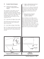
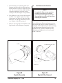
2.5.1
Compressed Air Inlet Adapter
(See Figure 3 Compressed Air Inlet
Adapter)
The compressed air inlet adapter is used for
converting the compressed air inlet from
National Pipe Threads to British Pipe Threads.
Install the compressed air inlet adapter as shown
in Figure 3 Compressed Air Inlet Adapter. Use
thread-sealing tape or pipe sealant on the
threaded adapter before screwing it into the
compressed air inlet.
2.5.2
Leg Levelers (See Figure 4 Leg Levelers)
The leveling mount foot pads screw into the
bottom of the collector legs as illustrated in
Figure 4 Leg Levelers.
2.5.3
Inlet Collar (See Figure 5 Inlet Collar)
Place 1/4" diameter sealant between the cabinet
side or top and the inlet collar. Attach the collar
using the eight (8) #6-32 thread cutting screws
provided.
2.5.4
Adapter to Round Outlet (See Figure 6
Adapter Pack to Round Outlet)
Place the 3/16" x 1/2" rubber seal between the
cabinet top and the outlet adapter. Attach the
outlet adapter to the cabinet using the clamp
hook, wing nut, and washer as shown. The
sliding damper will still operate with this
adapter.
2.5.5 Adapter Auto-Lok / Ultra-Lok
(See Figure 7 Adapter Pack
Auto-Lok / Ultra-Lok )
Remove the lift lug on the cabinet top and
replace it with the set screw. Place the 3/16" x
1-1/4" gasket between the cabinet top and the
adapter. Attach the adapter to the cabinet top
using the clamp hooks, wing nuts, and washers
as shown. Place the 3/8" x 1-1/4" gasket
between the adapter and the Auto-Lok or UltraLok filter as shown. Use the 10-24 x 7/16 screws
to attach the filter to the adapter. The sliding
damper will not operate with these adapters.
Compressed Air Inlet
Sealant
Compressed Air
Inlet Adapter
Collector
Leg
Collector
Leveling
Mount Foot
Pad
Leg or Caster
Figure 3
Compressed Air Inlet Adapter
8
Figure 4
Leg Levelers
Donaldson Company, Inc. © 1995
Inlet Collar
#6-32 Screws
Cabinet Top or Side
1/4" Diameter Sealant
Figure 5
Inlet Collar
Wing Nut
3/8 Flat Washer
Outlet Adapter
Rubber Seal
Clamp Hook
Cabinet Top
(Ref)
Figure 6
Adapter Pack to Round Outlet
Donaldson Company, Inc. © 1995
9
Auto-Lok /
Ultra-Lok
Assembly
3/8 x 1-1/4 Gasket
10-24 x 7/16 Screw
Adapter
Wing Nut
3/16 x 1-1/4 Gasket
3/8 Flat Washer
Set Screw
Cabinet Top (Ref)
Clamp Hook
Figure 7
Adapter Pack Auto-Lok / Ultra-Lok
10
Donaldson Company, Inc. © 1995
Filter Retainer Bar
1/4-20 x 3/4 Bolt
1/4 Flat Washer
HEPA /
Carbon Filter
1/4 x 3/4
Gasket
Adapter
Wing Nut
3/16 x 1-1/4 Gasket
3/8 Flat Washer
Set Screw
Cabinet Top (Ref)
Clamp Hook
Figure 8
Adapter Pack HEPA / Activated Carbon
Donaldson Company, Inc. © 1995
11
2.5.6
Adapter HEPA / Activated Carbon
(See Figure 8 Adapter Pack HEPA /
Activated Carbon)
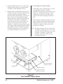
2.5.7
Remove the lift lug on the cabinet top and
replace it with the set screw. Place the 3/16" x
1-1/4" gasket between the cabinet top and the
adapter. Attach the adapter to the cabinet using
the clamp hooks, wing nuts, and washers as
shown. Place the 1/4" x 3/4" gasket between the
adapter and the HEPA or Activated Carbon
filter as shown. Use the filter retainer bar and
the 1/4" bolts and washers to attach the filter to
the adapter. The sliding damper will not operate
with these adapters.
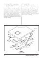
Leg Pack SDF
(See Figure 9 Leg Pack SDF)
The SDF units that are not furnished with a dust
container will have an internal hopper with a
base to attach to legs and crossbracing.
Assemble the legs and crossbracing to the SDF
base as shown in Figure 9 Leg Pack SDF. The
55-gallon drum pack leg crossbraces should be
installed on the three sides only, in order to
allow access to the drum. The 5-gallon pail pack
does not require crossbracing.
SDF Base
Crossbrace
Washer
Bolt
Crossbrace
Nut
Washer
Washer
Nut
Nut
Washer
Bolt
Washer
Leg
Washer
Bolt
Crossbracing
Figure 9
Leg Pack SDF
12
Donaldson Company, Inc. © 1995
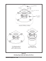
SDF Base
1/4" Dia. Seal
Bolts, Washers,
& Nuts
Attach to SDF Base as Shown
55-Gallon Drum Pack
With or Without Gate
With or Without Latches
5-Gallon Pail Pack
With or Without Gate
Figure 10
55-Gallon Drum Pack and 5-Gallon Pail Pack
Donaldson Company, Inc. © 1995
13
1/2" Diameter Holes (28)
Bin Vent Base
Figure 11
Bin Vent Base Pack
2.5.8
55-Gallon Drum Pack
(See Figure 10 55-Gallon Drum Pack
and 5-Gallon Pail Pack)
The 55-gallon drum cover and the 55-gallon
drum cover with gate can be attached to the
base as shown in Figure 10 55-Gallon Drum
Pack and 5-Gallon Pail Pack. Use the existing
bolts, washers, and nuts that are on the base.
Access to the bolts is through the hinged door.
Be sure to use sealant to seal between the drum
cover and the base.
14
2.5.9
5-Gallon Pail Pack
(See Figure 10 55-Gallon Drum Pack
and 5-Gallon Pail Pack)
Attach the 5-gallon pail cover and the 5-gallon
pail cover with gate as shown in Figure 10
55-Gallon Drum Pack and 5-Gallon Pail Pack.
2.5.10 Bin Vent Base Pack
(See Figure 11 Bin Vent Base Pack)
The Bin Vent pack for the SDF consists of a
base, as shown in Figure 11 Bin Vent Base Pack.
The Bin Vent base has twenty-eight (28) 1/2"
diameter holes for attachment in the field.
Donaldson Company, Inc. © 1995
M-6 Hex Bolts
(8 Req'd)
Flex-Trunk Assembly
(7-Foot Shown)
M-6 Thread Cutting
Bolts (12 Req'd)
Cover Plate
~
Swivel Base
5/16 Screw
5/16 Washer
Detail A
See Detail A
1/4" Diameter
Sealant
1/4" Diameter
Sealant
Use the bolts that are
removed from the cover
plate in Detail A
Flex-Trunk
Adapter
Figure 12
Flex-Trunk Assembly 7-Foot/10-Foot SDF
Donaldson Company, Inc. © 1995
15
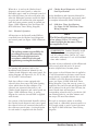
2.5.11 Flex-Trunk Assembly 7 Ft/10 Ft
(See Figure 12 Flex-Trunk Assembly)
Remove the cover plate bolts and the cover
plate from either the right or left side of the SDF
cabinet. Using the same cover plate bolts, attach
the Flex-Trunk Adapter to the side of the SDF
cabinet. Be sure to place 1/4" diameter sealant
between the adapter and the cabinet, as shown
in Figure 12 Flex-Trunk Assembly. Next, attach
the Flex-Trunk assembly to the adapter, being
sure to install more 1/4" sealant between the
adapter and the Flex-Trunk assembly. With the
swivel base positioned as shown in Figure 12
Flex-Trunk Assembly, secure the Flex-Trunk to
the adapter using the four (4) 5/16 slotted
screws and lock washers. For the adjustment
and operation of the Flex-Trunk, see the
Installation and Operation Manual for the FlexTrunk IOM-40779-00.
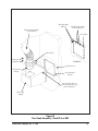
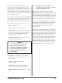
2.5.12 Weatherhood Pack
(See Figure 13 Weatherhood Pack)
Remove the bolts and the rear access panel to
the SDF. If the SDF is equipped with an outlet
damper (see Figure 1 SDF-4 Phantom View), this
damper must be removed. The weather hood
cannot be used with the outlet damper. Also,
remove the lift lug from the corner of the cabinet
and replace it with the M-16 set screw provided.
Place 1/4" diameter sealant between the cabinet
top and the weatherhood. Position the
weatherhood over the cabinet outlet, as shown
in Figure 13 Weatherhood Pack, and attach the
weather hood to the cabinet using the four M-6
bolts provided. These bolts should be inserted
through the slots on the cabinet roof and
screwed into the weld nuts on the weatherhood.
Replace the rear access panel and bolts.
16
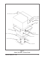
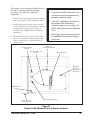
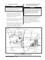
2.5.13 Explosion Vent Cabinet (See Figure 15
SDF-4 with Explosion Vents—Phantom
View)
When explosion vents are furnished on an SDF,
a special cabinet is required (see Figure 15 SDF4 with Explosion Vents—Phantom View). Some
features on this cabinet include:
•
A hinged access door to the dust container
with threaded handles and a reinforcing
bar.
•
Two 1/8" NPT couplings for dirty air (high
pressure) and clean air (low pressure)
fittings.
•
Two 3/4" NPT couplings for electrical
connections.
•
Openings for two 12 x 12 explosion vents.
Options available with this SDF cabinet in
addition to the 12 x 12 explosion vents include:
•
Explosion-Proof Motors.
•
Aluminum Blower Wheels.
•
NEMA 9 Explosion-Proof Solenoid
Enclosures.
•
Checker board in remote enclosure with
unwired electrical only.
NOTE
•
Explosion vent SDF units do not
contain an electrical compartment.
They are furnished from Torit
unwired.
•
All electrical work must be done by a
qualified electrician according to local
codes.
Donaldson Company, Inc. © 1995
Weatherhood
1/4" Dia Sealant
Cabinet Shown with
Rear Access Panel
Removed
M-6 Bolt
Replace Lift Lug
with Set Screw
Figure 13
Weatherhood Pack
Donaldson Company, Inc. © 1995
17
Remove cover plate.
Remove all bolts on cover plate and
save the bolts for attaching the
explosion vents to the cabinet.
Cabinet (Ref)
Detail A
12 x 12
Explosion Vent
Silicone
Sealant
Hex Nut
Lock Washer
12 x 12
Explosion Vent
Hex Bolt
See Detail A
12 x 12
Weather Cover
1/4" Wide Tab
Use the bolts that are removed from the
cover plate in Detail A.
Tighten bolts only until vent flange
begins to deform. Do not overtighten.
Figure 14
Explosion Vent Pack
18
Donaldson Company, Inc. © 1995
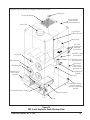
Sprinkler Taps (not shown) (not supplied standard with the SDF)
Lifting Eyes
Outlet with Damper
Screwed-on Rear
Access Panel to
Blower Compartment
Inlet Collar
Opening for
Explosion Vents
Blower Pack
3/4" NPT
Couplings for
Electrical
Connections
1/8 NPT Coupling
(Low Pressure)
Filter Yoke
1/8 NPT Coupling
(High Pressure)
Filter Element
Screwed-on
Rear Access
Panel to Clean
Air Manifold
Filter Wing Nut
Hinged Access
Door to Dust
Container
Air Manifold
Assembly
Venturi
Compressed Air Inlet—
1/2 National Pipe
Threads or British Pipe
Threads
Lift Assembly Dust Container
Dust Container
Legs
Figure 15
SDF-4 with Explosion Vents Phantom View
Donaldson Company, Inc. © 1995
19
2.5.13 Explosion Vent Pack
(See Figure 14 Explosion Vent Pack)
Remove the cover plate bolts and the cover plate
from the side of the SDF cabinet. Using the same
cover plate bolts, attach the 12 x 12 explosion
vents to the side of the SDF cabinet. Be sure to
apply silicone sealant between the bolted flanges
and the cabinet, as shown in Figure 14 Explosion
Vent Pack. Tighten the bolts only until the vent
frame flange starts to bend. Do not overtighten.
The 12 x 12 weather cover should be used for
outside applications. Apply silicone sealant only
along the bolted flange of the weather cover.
Attach the weather cover to the explosion vent
flange using bolts, lock washers and nuts as
shown. Also bend the 1.4 inch wide tab 180
degrees over and press firmly against the
explosion vent frame. Do this on both sides of
the weather cover.
For operating precautions, technical data and
rearming instructions for the explosion vents, see
the Torit Explosion Vent Manual
IOM-72087-01.
CAUTION
•
Explosion relief vents are required on
some applications.
•
Consult with an insurance underwriter
or a NFPA Manual to determine proper
vent sizing requirements.
Vents installed on dust collection
equipment within a building must relieve
to the outside of the building to
minimize chances of a secondary
explosion.
Consult the proper authority to
determine proper method of venting the
dust collection equipment.
Torit equipment does NOT contain
explosion relief vents, except on special
order.
•
•
•
CAUTION
Remote controls are required for units
handling combustible or explosive dusts.
20
2.6 Electrical Installation
The Downsized Downflo dust collector is
available with four versions of electrical
components:
1. Pre-wired with the Checker board on the
unit (see Figure 16 Pre-Wired with Checker
Board on Unit)
2. Unwired with the Checker board on the
unit (see Figure 17 Unwired with Checker
Board on Unit)
3. Pre-wired with the Checker board in a
remote enclosure (see Figure 18 Pre-Wired
with Checker Board in Remote Enclosure)
4. Unwired with the Checker board in a
remote enclosure (see Figure 19 Unwired
with Checker Board in Remote Enclosure).
The pre-wired version with the Checker board
on the unit has been completely wired at the
factory. Before it is ready for operation, a plug
must be attached to the power cord and the unit
must be connected to a duct.
The unwired version with the Checker board on
the unit has only the solenoid valves and the
temperature sensor wired at the factory.
A proper-sized motor starter needs to be
mounted externally or in the electrical
compartment. A proper-sized power cord and
plug also needs to be installed. Using the wiring
diagrams (Figures 20 through 27) make the
proper connections to the blower motor, blower
motor starter, and the Checker board.
All electrical apparatus should be properly sized
for the required voltage and motor full load
amperage.
NOTE
•
All electrical work must be done by a
qualified electrician according to local
codes.
•
The plug attached to the power cord
must be for the correct voltage as
designated.
Donaldson Company, Inc. © 1995
Safety Filters
Vinyl Tubing
Checker
board
To Low Pressure
Vinyl Tubing
Door Shown in
Open Position
Power Cord
To High Pressure
Figure 16
Prewired with Checker Board on Unit
Checker board
Door Shown in
Open Position
Vinyl Tubing
Safety Filters
Wiring to
Solenoid Valves
Wiring to
Temperature Sensors
Access for Wiring
to Motor
Mounting Panel for
Motor Starter
To Low Pressure
To High Pressure
Access for
Power Cord
Figure 17
Unwired with Checker Board on Unit
Donaldson Company, Inc. © 1995
21
The pre-wired version with the Checker board
in the remote enclosure should be installed
according to the following steps.
1.
Mount the Checker board enclosure in a
location convenient for the machine
operator (see Figure 28 Remote Checker
Board Assembly).
2.
Install conduit between the electrical
compartment and the remote enclosure. Use
sealed fittings, making all connections leak
tight.
3.
Wire from the terminal strip in the electrical
compartment to the terminal strip in the
remote enclosure (see Wiring Diagrams
Figures 20 through 27).
4.
Drill mounting holes in the electrical
compartment to accept the bulkhead
pneumatic fittings shipped with the
collector. Install them on the most
convenient side of the collector, typically
adjacent to the conduit. Connect the 1/8"
ID vinyl tubing from the pressure taps inside
the electrical compartment to the bulkhead
fittings, and then from the bulkhead fittings
to the mating fittings on the Checker board
enclosure. Loosely fasten the vinyl tubing to
the conduit for support, being careful not to
flatten the tubing.
5.
The pneumatic fitting located on the vertical
surface of the electrical compartment is the
low pressure fitting, and the fitting on the
horizontal surface is the high pressure
fitting. The Checker board enclosure has the
low pressure fitting closest to the front cover
and the high pressure fitting located closest
to the back of the enclosure.
Terminal Strip
Mounting
Panel
Ground Lug
Factory Wired
Motor Starter
Power Cord
High Pressure
Fitting
Door Shown in
Open Position
Low Pressure Fitting
Fuse Kits and
Transformer
Figure 18
Prewired with Checker Board in Remote Enclosure
22
Donaldson Company, Inc. © 1995
The unwired version with the Checker board in
the remote enclosure should be installed
according to the following additional
instructions.
1.
Remove the back panel to access the blower
motor (see Figure 1 SDF-4 Phantom View).
2.
Install and wire the motor starter, control
circuit transformer, and other motor control
components as required (see Figure 19
Unwired with Checker Board in Remote
Enclosure).
3.
Wire the motor to the motor starter using
the factory installed conduit between the
motor connection box and the electrical
compartment.
NOTE
•
Explosion vent SDF collectors do not
contain an electrical compartment or
internal conduit for wiring.
•
Two 3/4" couplings are provided on
the outside of the collector for
electrical wiring access (see Figure 15
SDF-4 with Explosion Vents Phantom
View).
•
All wiring on these units must be done
by a qualified electrician according to
local codes.
Wiring to
Access for Wiring
Temperature Sensor
to Motor
Wiring to Solenoid
Valves
Terminal Strip
Mounting
Panel for
Motor Starter
(By others)
High Pressure
Fitting
Door Shown in
Open Position
Low Pressure Fitting
Figure 19
Unwired with Checker Board in Remote Enclosure
Donaldson Company, Inc. © 1995
23
From 575VAC 60Hz, 3 Phase
Disconnect means and circuit protection by others
L1
L2 L3
G
FU1
1A
H4
X1
H3
X2
115VAC
H2
H1
FU2
1A
L1
L2
FU3
3-2/10A
X3
N
T1
250VA
L3
M1
RELAY 7 13
SV6
TB12
RELAY 6 12
SV5
TB11
RELAY 11
5
SV4
TB10
RELAY 4 10
SV3
TB9
RELAY 3
9
SV2
TB8
RELAY
2
8
SV1
TB7
RELAY
1
2
M1
6
A1
TB6
CLEANING
VALVE NO. 5
CLEANING
VALVE NO. 4
CLEANING
VALVE NO. 3
CLEANING
VALVE NO. 2
CLEANING
VALVE NO. 1
OL1
7
A2
CLEANING
VALVE NO. 6
95
MOTOR STARTER
96
INTERFACE
BOARD
CUR 1
TE1
T3
NOTE: From CUR 3 wrap wire lead 1 turn
(2 turns for 3,5 hp) through sensor
core CUR 1 before returning to CUR 3.
IT3
CONTROLBOARD
CUR 3
TEMP 1
4 5
TB4
NEUT
TB2
IN
TB1A
IN
TB1
BLOWER
3,5,7-1/2,10 hp
N N1
OUT
1 2
IT3
ON/OFF
T3
OUT
T2
HOT
T1
CLEAN AIR TEMPERATURE
OL1
Figure 20
Wiring Diagram 575 Volt - 60 Hz, 3PH – 3, 5, 7-1/2, 10 hp
G L1 L2 L3
N
RELAY 6
24VDC Power
Supply
L3
L1 FU2
N1
NEUTRAL
3A
+24VDC
LINE-24VDC
M1
RELAY 4
TB8
RELAY 3
GND
10
SV3
9
SV2
SV1
TB7 8
RELAY
2
T1 T2 T3
(U1)(V1) (W1)
TB6
2
RELAY
1
CLEANING
VALVE NO. 6
CLEANING
VALVE NO. 5
CLEANING
VALVE NO. 4
CLEANING
VALVE NO. 3
CLEANING
VALVE NO. 2
CLEANING
VALVE NO. 1
6 OL1 7 M1
95 96 A1 A2
CUR 1
TE1
CLEAN AIR TEMPERATURE
CUR 3
4 5
TB4
TEMP 1
ON/OFF
TB2
IN
TB1A IN
NEUT OUT
HOT
OUT
1 2 N N1
TB1
INTERFACE
BOARD
MOTORSTARTER
IT3
3.75
KW
SV4
TB10 11
RELAY
5
TB9
+DC
-DC
OL1
BLOWER
3,5 hp
SV5
TB1112
PSI
L1 L2
SV6
TB1213
RELAY 7
FU1
1.5A
From 380VAC 50Hz, 3 Phase
Disconnect means and circuit protection by others
T3
IT3
CONTROLBOARD
NOTE: From CUR 3 wrap wire lead 1 turn
through sensor core CUR 1 before
returning to CUR 3.
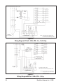
Figure 21
Wiring Diagram 380 Volt - 50 Hz, 3PH – 3, 5 hp
24
Donaldson Company, Inc. © 1995
G L1 L2 L3
SV6
TB1213
RELAY 7
N
FU1
1.5A
TB11 12
RELAY 6
CLEANING
VALVE NO.5
SV4
TB10 11
RELAY
5
TB9 10
RELAY 4
CLEANING
VALVE NO.4
SV3
TB8
RELAY 3
9
SV2
TB7
RELAY
2
8
SV1
CLEANING
VALVE NO.3
CLEANING
VALVE NO.2
CLEANING
VALVE
NO. 1
PSI
+DC
-DC
7 TR1 8
9 M5
15 18 21 22 A1M3 A2
15 16 21 22 A1TR1 A2
M1
53M354
A1 M1 A2
OL1
6
95 96
TB6
24VDC Power
Supply
3A
+24VDC
L1 FU2
LINE -24VDC
N1 NEUTRAL
CLEANING
VALVE NO.6
SV5
RELAY
1
13 14
A1
A2
DELTA
CONTACTOR
WYE
CONTACTOR
TIME DELAY
ON
ENERGIZE
MAIN
CONTACTOR
BLOWER
7-1/2 hp
T2
L2
T1
L1
CUR 1
INTERFACE
BOARD
TE1
NN1
CUR 3
T3M3L3 19
T5
(V2)
T4
(U2)
T6
(W2)
5.5
KW
STARTER
4 5
L3
Y-
N1
From 380VAC 50Hz, 3 Phase
Disconnect means and circuit
protection by others
CONTROL
BOARD
IL3
IN
2
HOT OUT
TB1A
IN
NEUTOUT
TB2
T1 T2 T3
(U1)(V1) (W1)
IL1 TB1
OL1
TB4
TEMP 1
L3 L2 L1
M5
T1 T2 T3
ON/OFF
M1
T1 T2 T3
CLEAN AIR
TEMPERATURE
GND
L1 L2 L3
NOTE: From CUR 3 wrap wire lead 1 turn
through sensor core CUR 1 before
returning to CUR 3.
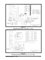
Figure 22
Wiring Diagram 380 Volt - 50 Hz, 3PH – 7-1/2 hp
From 230VAC 60Hz, 3 Phase
Disconnect means and circuit protection by others
L1 L2 L3 G
H4
X1
H3
FU1
3A
FU2
3A
L1
L2
X2
H2
RELAY 7
FU3
3-2/10A
TB12
RELAY 6
115VAC
TB11
RELAY
5
TB10
RELAY 4
H1
X3 N
T1
250VA
TB9
RELAY 3
L3
M1
SV5
12
CLEANING
VALVE NO. 6
CLEANING
VALVE NO. 5
SV4
11
10
SV3
9
SV2
8
SV1
M1
6
CLEANING
VALVE NO. 3
CLEANING
VALVE NO. 2
CLEANING
VALVE NO. 1
7 OL1
A2 95 96
MOTOR STARTER
INTERFACE
BOARD
A1
CLEANING
VALVE NO. 4
TEMP 1
T3
IT3
CONTROLBOARD
CUR 3
4 5
TB2
IN
N N1
NEUT OUT
IN
TB1
HOT
IT3
BLOWER
3,5,7-1/2,10 hp
OUT
1 2
TE1
T3
TB1A
T2
CUR 1
OL1
T1
ON/OFF CLEAN AIR TEMPERATURE
TB4
2
TB8
RELAY
2
TB7
RELAY
1
TB6
SV6
13
NOTE: From CUR 3 wrap wire lead 1 turn
through sensor core CUR 1 before
returning to CUR 3.
Figure 23
Wiring Diagram 230 Volt - 60 Hz, 3PH – 3, 5, 7-1/2 , 10 hp
Donaldson Company, Inc. © 1995
25
L1
G
L2
L3
FU1
3A
FU2
3A
L1
L2
RELAY 7
13
SV6
TB12
RELAY 6
12
SV5
TB11
RELAY
5
TB10
RELAY 4
L3
M1
10
SV3
9
SV2
8
SV1
TB9
RELAY 3
OL1
TB8
2
M1
6
A1
OL1
7
95
A2
96
CLEANING
VALVE NO. 4
CLEANING
VALVE NO. 3
CLEANING
VALVE NO. 2
CLEANING
VALVE NO. 1
MOTOR STARTER
TE1
T3
CUR 3
From 200VAC 50/ 60Hz, 3 Phase
Disconnect means and circuit protection by others
NOTE: From CUR 3 wrap wire lead 1 turn
through sensor core CUR 1 before
returning to CUR 3.
IT3
CONTROLBOARD
TEMP 1
TB2
TB4
4 5
ON/OFF
IN
NEUT OUT
TB1A
TB1
HOT
IN
OUT
1 2 N N1
3.75
KW
CUR 1
CLEAN AIR TEMPERATURE
IT3
BLOWER
3,5 hp
RELAY
2
TB7
RELAY
1
TB6
CLEANING
VALVE NO. 5
INTERFACE
BOARD
T1 T2 T3
(U1) (V1) (W1)
SV4
11
CLEANING
VALVE NO. 6
Figure 24
Wiring Diagram 200 Volt - 50/60 Hz, 3PH – 3, 5 hp
L3
TB12
RELAY 7
FU1
3A
FU2
3A
T2
L2
L3 T3
T3
L3
2
15
SV3
TB8
RELAY 3
14
SV2
M5 12
TR1 8 M3
9
15 18 21 22 A1 A2
10 M5 11 M3
A2
15 16 21 22 A1
TR1
7
M1
A1 A2
43 44
M1
M3
A1 A2
13 14
6
(V2)
(U2)
T6
(W2)
2
TB1
IN
HOT OUT
T4
22
4 5
CUR 3
OL1
CUR 1
Y– STARTER
M1
CLEANING
VALVE NO. 4
CLEANING
VALVE NO. 3
CLEANING
VALVE NO. 2
SV1
13
TB7
RELAY
2
TB6
RELAY
1
CLEANING
VALVE NO. 5
SV4
16
TE1
5.5
BLOWER KW
7-1/2, 10 hp
L1 21
CLEANING
VALVE NO. 6
19
20
CLEANING
VALVE NO. 1
DELTA
CONTACTOR
WYE
CONTACTOR
96
TIME DELAY
ON ENERGIZE
MAIN
CONTACTOR
INTERFACE
BOARD
T2
T5
17
SV5
TB10
RELAY
5
TB9
RELAY 4
CLEAN AIR TEMPERATURE
T1 T2 T3
(U1) (V1)(W1)
SV6
TB4
TEMP 1
T2 T3
L2
M3
IL2
T1
T1
TB1A IN
NEUTOUT
L2 L3
M5
L1 T1
IL1
L1
TB11
18
RELAY 6
TB2
ON/OFF
G L1 L2
CONTROL
BOARD
From 200VAC 50/60Hz, 3 Phase
Disconnect means and circuit protection by others
NOTE: From CUR 3 wrap wire lead 1 turn
through sensor core CUR 1 before
returning to CUR 3.
Figure 25
Wiring Diagram 200 Volt - 50/60 Hz, 3PH – 7-1/2, 10 hp
26
Donaldson Company, Inc. © 1995
L1
L2
L3
G
FU1
1-1/2A
FU2
1-1/2A
L1
L2
RELAY 7
X1
H4
H3
FU3
X2 3-2/10A
H2
115VAC
X3
H1
TB12
RELAY 6
N
T1
250VA
RELAY 3
TB8
RELAY
2
TB7
RELAY
1
TB6
L3
M1
OL1
12
CLEANING
VALVE NO. 5
SV4
CLEANING
VALVE NO. 4
SV3
9
SV2
8
SV1
M1
6
A1
CLEANING
VALVE NO. 3
CLEANING
VALVE NO. 2
CLEANING
VALVE NO. 1
OL1
7
A2 95
MOTOR STARTER
96
IT3
CUR 3
T3
CONTROLBOARD
From 460VAC 60Hz, 3 Phase
Disconnect means and circuit protection by others
NOTE: From CUR 3 wrap wire lead 1 turn
through sensor core CUR 1 before
returning to CUR 3.
IT3
TB2
TB1A IN
HOT
NEUT OUT
IN
OUT
TB1
ON/OFF
4 5
1 2 N N1
BLOWER
3,5,7-1/2,10 hp
INTERFACE
BOARD
TE1
CUR 1
CLEAN AIR TEMPERATURE
T3
TB4
TEMP 1
T2
CLEANING
VALVE NO. 6
SV5
TB11
RELAY 11
5
TB10
RELAY 4 10
TB9
2
T1
SV6
13
Figure 26
Wiring Diagram 460 Volt - 60 Hz, 3PH – 3, 5, 7-1/2, 10 hp
L1
L2
L3
G
H4
X1
H3
FU1
3A
FU2
3A
L1
L2
X2
H2
RELAY 7
FU3
3-2/10A
TB12
RELAY 6
115VAC
TB11
RELAY
5
H1
X3 N
T1
250VA
L3
M1
IT3
TEMP 1
T3
CONTROLBOARD
CUR 3
4 5
TB2
NEUT OUT
N N1
IN
IN
TB1
HOT
BLOWER
3,5,7-1/2,10 hp
OUT
1 2
IT3
SV5
12
CLEANING
VALVE NO. 5
SV4
11
TB10
RELAY 4
10
SV3
TB9
RELAY 3
9
SV2
8
SV1
TB8
RELAY
2
TB7
RELAY
1
TB6
CLEANING
VALVE NO. 6
M1
6
A1
7 OL1
A2 95 96
CLEANING
VALVE NO. 4
CLEANING
VALVE NO. 3
CLEANING
VALVE NO. 2
CLEANING
VALVE NO. 1
MOTOR STARTER
INTERFACE
BOARD
TE1
T3
TB1A
T2
CUR 1
OL1
T1
ON/OFF CLEAN AIR TEMPERATURE
TB4
2
SV6
13
From 208VAC 60Hz, 3 Phase
Disconnect means and circuit protection by others
NOTE: From CUR 3 wrap wire lead 1 turn
through sensor core CUR 1 before
returning to CUR 3.
Figure 27
Wiring Diagram 208 Volt - 60 Hz, 3PH – 3, 5, 7-1/2, 10 hp
Donaldson Company, Inc. © 1995
27
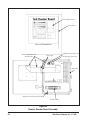
Control Panel Label
Control Box
Cover of Control Box
Remote Checker board
Assembly Kit
High Pressure (Dirty Air)
Flat Cable
Low Pressure (Clean Air)
Control Box
High and Low Pressure Fittings
Terminal Strip
Figure 28
Remote Checker Board Assembly
28
Donaldson Company, Inc. © 1995
If the model SDF is purchased with a solid state
timer in the unit instead of the Checker board,
the timer will be wired to the solenoid valves.
If the timer is to be remote mounted, it will be
furnished unwired. A properly sized motor
starter needs to be mounted in addition to the
timer. Using the wiring diagram in Figure 29
SDF Solid-State Timer Wiring Diagram, make
the proper connections to the blower motor,
blower motor starter, and solid state timer.
CAUTION
Do not interchange a power lead and
the ground wire.
CAUTION
Disconnect electrical power before
servicing any electrical component.
After attaching the plug and starting the blower
motor, check for proper rotation. It should be
clockwise when looking down at the top of the
blower motor. Also, reference the rotation
sticker on the blower housing (see Figure 1
SDF-4 Phantom View). Proper blower rotation is
extremely important. If the blower is running in
the wrong direction, it will only deliver
approximately 40% of its rated air volume.
Interchange any two power wire leads (3 phase
only) on the plug to reverse rotation.
With the blower motor starter turned on, check
operation of the solenoid valves. When the
Checker board is used, press and hold the
CONSTANT CLEAN push button and pulsing
will begin. The valves should open and close
continuously with a factory set interval time of
10 seconds between each cleaning pulse.
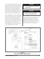
CONTROL BOX
L1
IL1
2FU
IL2
IT2
3FU
IL3
IT3
L2
L3
IOL
IM
1FU
230V 30
60N
IT1
FAN
I MTR
OFF TIME
H2
X1
H4
X2
115V
TIMING
LOGIC
POWER
SUPPLY
START
STOP
PROGRAM LUG
PROGRAM PINS
PRESSURE
SWITCH
230V
H3
H1
ON TIME
IM
CONTROL
LOGIC
IM
ITGS
4FU
460V
H1
SOL
COM1
2
3
4
5
6
H4
H2
H3
3AMP
L1 L2
SOLENOID VALVES
X1
115V
X2
Figure 29
SDF Solid-State Timer Wiring Diagram
Donaldson Company, Inc. © 1995
29
When the ® is used on the Checker board
diagnostic and control panel, or when the
Photohelic gage is used as an internal control of
the solid-state timer, the valves will pulse only
when the differential pressure reaches the high
set point and will continue the pulse sequence
until the lowest pressure setting is reached (see
Figure 1 SDF-4 Phantom View and Figure 29
SDF Solid-State Timer Wiring Diagram).
2.6.1
2.6.2
Checker Board Diagnostics and Control
Panel Specifications
See the Installation and Operation Manual for
the Checker Board diagnostic and control panel
for complete information (IOM-72202-00)
2.6.3
Solid-State Timer Specifications
(See Figure 29 SDF Solid-State Timer
Wiring Diagram)
Electrical Operation
All functions on the Downflo model SDF are
controlled from the Checker board diagnostic
and control panel (see Figure 1 SDF-4 Phantom
View).
NOTE
The SDF model solid-state timer requires
a low voltage (105 to 135 volt AC)
control circuit in the fan starter. This is
not supplied by Torit.
NOTE
The end user assumes responsibility for
providing all necessary disconnecting
means and overload protection in
accordance with all local codes and
regulations governing this installation.
For starting and operation, refer to the
Installation and Operations Manual for the
Checker board diagnostic and control panel. For
wiring diagrams, see Figures 20, 21, 22, 23, 24,
25, 26, and 27 in this manual.
COMPONENTS: Standard Downflo model
SDF dust collectors are equipped with 115
volt AC solenoid valves rated at 19.7 watts
each and a solid-state 115 volt AC/50-60Hz/1
timer when ordered.
The timer is factory-adjusted at 100 milliseconds
(1/10 second) pulse time and a 10 second
duration (elapsed time) between pulses.
Each dust collector comes equipped with
solenoid valves that control the pulse cleaning
valves which clean the filter elements. The
solenoids are connected electrically to the
Checker board diagnostic and control panel (see
Figure 1 SDF-4 Phantom View). A wiring
diagram for each size of model SDF is supplied
with the unit.
Input power to the solid-state timer is applied to
L1 and L2 terminals on the timer control circuit
board, which is in parallel with the low voltage
(115/60/1) coil of the blower fan magnetic
starter (see Figure 29 SDF Solid-State Timer
Wiring Diagram). Upon fan start-up, power is
supplied to the control board and the preset OFF
time is initiated. At the end of the OFF time, the
control board timer will energize a
corresponding solenoid valve to provide the ON
time cleaning pulse for one filter element and
then step to the next filter element.
On versions of the Downsized Downflo without
the Checker board diagnostic and control panel,
the solenoid valves are connected electrically to
the solid-state control timer. A wiring diagram
for each model is supplied with this version.
This cycle is continuous unless an auxiliary
control such as a Photohelic pressure switch or a
1TGS toggle switch is used to control the timer
(see Figure 29 SDF Solid-State Timer Wiring
Diagram).
30
Donaldson Company, Inc. © 1995
When all of the available outputs are not
required, programming the control board for
fewer outputs is accomplished by resetting the
program pin selection wire on the solid-state
control board to the correct number of solenoid
valves being used (see Figure 29 SDF Solid-State
Timer Wiring Diagram).
The 1TGS is an optional switch (not supplied by
Torit) and provides a means of control when the
pulse sequence is activated. Consult your local
Torit representative before using this method.
In grounded systems, neutral to control box
must be connected to L2.
Input: 105-135 VAC/50-60 Hz/1
Output Solenoids: Type—solid-state switch
(Triac). The load is carried by and turned on
and off by the Triac. Rating–200 watts
maximum load per output.
Pulse Width (ON Time): Factory set at 100
milliseconds (1/10 second).
NOTE
Do not adjust ON time unless the
proper test equipment is used.
Too much or too little ON time can
cause shortened filter element life.
Consult with your local Torit
representative.
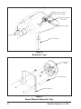
2.6.4
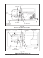
Magnehelic Gage (See Figure 30
Magnehelic Gage & Figure 31 RemoteMounted Magnehelic Gage)
Some units are supplied with an optional
Magnehelic gage where the gage, pressure taps,
and tubing have been preinstalled in our factory.
Zero and maintain the Magnehelic gage per the
operating and maintenance instructions provided
by the manufacturer of the Magnehelic gage.
For remote-mounted gages, the plastic tubing
will determine the distance away from the unit
that the gage can be located. If more tubing is
required, please contact your local Torit
representative.
Mount the remote gages as shown in Figure 31
Remote-Mounted Magnehelic Gage. Make the
connections as shown in Figure 30 Magnehelic
Gage. The high pressure port is connected to the
dirty air plenum. The low pressure port is
connected to the clean air plenum. The high and
low pressure connections are located in the
electrical compartment of the collector. Use
bulkhead fittings and mount them through the
cabinet to the electrical compartment. Zero and
maintain the gage per operating instructions.
OFF Time: Adjustable–1 to 1.5 seconds
minimum, 30 seconds maximum, factory set
at 10 seconds.
Operating Temperature Range:
-20°F to 130°F.
Transient Protection: 50kW transient of
20ms duration once every 2 seconds.
Solenoid Valves: 115 volts AC at 19.7 watts
each.
Donaldson Company, Inc. © 1995
31
High Pressure Port (Ref)
Low Pressure Port (Ref)
Tubing Male Adapters
1/8" NPT
Magnehelic
Gage
Plastic Tubing
Clean Air Plenum
Dirty Air Plenum
Figure 30
Magnehelic Gage
Magnehelic
Gage
Screw Self-Drilling
Mounting Panel
Figure 31
Remote-Mounted Magnehelic Gage
32
Donaldson Company, Inc. © 1995
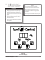
2.6.5
Torit ∆ P Control (See Figure 32
Torit ∆ P Control Wiring Diagram &
Figure 33 Printed Circuit Board )
CAUTION
•
All electrical work is to be done by a
qualified electrician according to the
national and local electrical codes that
apply.
•
All electrical power must be shut off
during installation.
•
Do not apply in hazardous (classified)
atmospheres.
NOTE
•
Do not mount controls in a high
vibration area without shock mounts.
•
Do not mount controls in corrosive
atmospheres without an appropriate
enclosure.
•
Do not operate with the enclosure open.
Figure 32
∆P Control Display
Donaldson Company, Inc. © 1995
33
CAUTION
3.
Apply power to the ∆P Control, adjust the
setpoints for the High and Low setpoints—
the pressure drops that start and stop the
cleaning process—and the Alarm setpoint.
4.
Press and hold one of the setpoint push
buttons. While holding down the push
button, use the up and down arrow keys to
adjust that setting. The setpoints will always
be in the same units as chosen for the
pressure display. Adjust the remaining
values in the same manner.
STATIC-SENSITIVE ELECTRONIC ASSEMBLY
•
Use proper grounding and handling
procedures to prevent permanent
damage to this device.
•
If it is necessary to remove the printed
circuit board, handle only by the edges.
•
Avoid touching the socketed E2PROM
pins.
Optional Settings
230 Volt Power Supply
Some units are supplied with an optional Torit
∆P Control, with the control, pressure taps, and
tubing preinstalled in our factory.
To operate at 230 VAC remove the two jumpers
labeled W1 and W3, reinsert one of the jumpers
in position W2.
1.
Change Units from Inches of Water to
Millimeters of Water
2.
Using the wiring diagram (Figure 33 Printed
Circuit Board), wire all connections for the
motor, ∆P Control (TB1), the solenoid timer
control, and solenoid valves.
Wire the alarm circuit labeled AUXILIARY,
if desired. When the pressure drop reaches
the preset ALARM value, the relay will
actuate and the LED light labeled ALARM
on the user interface will illuminate. The
AUXILIARY relay can be used to actuate
visual and/or audible alarms (by others).
NOTE
This control has a factory default
voltage selection of 115 VAC. If you plan
to operate at 230 VAC, change the
jumper settings as shown on the printed
circuit board and as described in
OPTIONAL SETTINGS in Section 2.6.5
Torit ∆P Control.
34
To have all units displayed as mm wg, locate the
jumper block labeled J1, located just above the
PROG DISABLE terminals at the bottom edge of
the printed circuit board. Remove the jumper
from the center and left pins (numbered 2 & 3),
and reinstall on the center and right pins
(numbered 1 & 2).
Disabling the Setpoint Adjustments
To restrict the ability to change the setpoints,
install a jumper wire across the PROGRAM
DISABLE terminals on Terminal Block 2 (TB2).
This will allow the operator to press the
appropriate set keys to determine the current
settings, but will not allow any changes until the
jumper wire is removed.
Installing a key-operated, normally closed
switch through the door of the enclosure that
interrupts the jumper wire will provide
temporary access to the setting function without
opening the control enclosure.
Donaldson Company, Inc. © 1995
External Alarm Reset
Locate the terminal block in the lower right
quadrant of the printed circuit board labeled
ARM. RESET (TB2). Wire this terminal block to
a normally open key-operated switch. Closing
the switch will turn off the alarm and disable it
until the switch is reopened. Momentarily
closing the switch will turn off the alarm, but if
the alarm conditions still exist, the alarm relay
will latch on again in 10 seconds (see Figure 33
Printed Circuit Board).
Disable the Alarm
Locate the jumper block in the lower right
quadrant of the printed circuit board labeled
MODE (J5). Remove the jumper from the
ALARM position. Disabling the Alarm Relay
reduces the alarm function to lighting the LED
on the user interface.
Reinstalling the jumper in the SLAVE position
(upper and middle pins) causes the AUXILIARY
relay to operate in parallel with the HI/LO
CONTROL relay.
If the jumper is not installed in either position,
the AUXILIARY relay does not function.
Analog Output
Locate the terminal block in the upper left
quadrant labeled SENSOR OUT (TB4). This
connector provides a 1-5 VDC output
proportional to the 0 to maximum span of the
pressure sensor, 10K ohm load minimum (see
Figure 33 Printed Circuit Board).
Alarm Disable
Hi/Lo Timer
Control Relay
Alarm or
Auxiliary Relay
{
{
{
{
Voltage Choice Jumpers
Power Connections
Units ("wg or mm wg)
Remote Alarm Reset
Disable Programming
Figure 33
Printed Circuit Board
Donaldson Company, Inc. © 1995
35
High Pressure Port (Ref)
Low Pressure Port (Ref)
Tubing Male
Adapters 1/8" NPT
Plastic Tubing
Photohelic
Gage
Clean Air Plenum
Dirty Air Plenum
Figure 34
Photohelic Gage
Photohelic Gage
Mounting Bracket
Screw Self-Drilling
Figure 35
Remote-Mounted Photohelic Gage
36
Donaldson Company, Inc. © 1995
2.6.6
Photohelic Gage (See Figure 34
Photohelic Gage & Figure 35 RemoteMounted Photohelic Gage)
Some units are supplied with an optional
Photohelic gage where the gage, pressure taps,
and tubing have been preinstalled in our factory.
Proper wiring of the gage is necessary.
1.
Remove the four (4)#6-32 x 5/16 long
screws and plastic enclosure on the back of
the Photohelic gage and set aside.
2.
Add the two jumper wires (not supplied by
Torit) and wire the gage using 3/4" conduit
opening, as shown in Figure 36 Photohelic
Gage Wiring Diagram.
3.
Reassemble the plastic enclosure and fasten
securely, using the #6-32 x 5/16" long
screws previously removed.
4.
Zero and maintain the Photohelic gage per
the operating and maintenance instructions
provided by the manufacturer of the
Photohelic gage.
For remote-mounted gages, the plastic tubing
will determine the distance away from the unit
that the gage can be located. If more tubing is
required, please contact your local Torit
representative.
Mount the remote gages as shown in Figure 35
Remote-Mounted Photohelic Gage. Make the
connections as shown in Figure 32 Photohelic
Gage. The high pressure port is connected to the
dirty air plenum. The low pressure port is
connected to the clean air plenum. The high and
low pressure connections are located in the
electrical compartment. Use bulkhead fittings
and mount them through the cabinet to the
electrical compartment. Wire the Photohelic
gage per the instructions previously stated in this
section.
NEUT
110VAC
From main
control panel
∆P Control
Solenoid Valves
PRESSURE
SWITCH
Remove factory installed
jumper on timer labeled
(Pressure Switch)
Timer Board
*For use with Solid State Timer only
Wiring by others
Figure 36
Photohelic Gage Wiring Diagram
Donaldson Company, Inc. © 1995
37
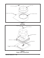
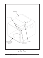
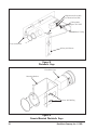
2.7
Compressed Air Supply Installation
(See Figure 1 SDF-4 Phantom View)
Remove the plastic pipe plug from the
compressed air connection at the bottom of the
collector (see Figure 1 SDF-4 Phantom View)
and connect the compressed air supply line. Use
thread-sealing tape or pipe sealant on all
compressed air connections. Use quickdisconnect fittings if possible. Be sure that all
compressed air components are adequately sized
to meet the maximum system requirements of
1.1 scf per pulse at 90-100 psig supply pressure.
NOTE
It is important that the compressed air
supply be both oil and moisture free.
Contamination in the compressed air
line that is used to clean filter elements
will result in poor cleaning or cleaning
valve failure and a reduction in dust
collector performance.
If the compressed air inlet adapter is used to
convert the NPT threads to British pipe threads,
see Figure 3 Compressed Air Inlet Adapters for
assembly.
Manifold Weldment
Solenoid Coil
Diaphragm
Air Valve
Solenoid Valve
Manifold Mounting Bracket
Figure 37
Air Manifold Assembly
38
Donaldson Company, Inc. © 1995
2.7.1
Air Manifold Assembly
(See Figure 37 Air Manifold Assembly)
To access the air manifold assembly, remove the
screws on the back (see Figure 1 SDF-4 Phantom
View) and lift the rear access panel off. The
manifold assembly contains diaphragm air
valves, solenoid valves, the manifold weldment,
and the manifold brackets. See the Replacement
Parts List for authorized Torit replacement
parts.
When replacing the rear access panel, be sure
the gasket is not damaged and the screws are
tight, or leakage may occur.
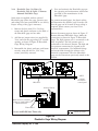
2.7.2
4.0 START–UP
1.
Turn on the compressed air supply to the
Downflo model SDF dust collector
compressed air manifold. Adjust to 90 psig
of pressure, minimum. Pressure of
90-100 psig is the most typical setting for
satisfactory cleaning performance (see
Section 5.0 Operating Adjustments).
The lower the compressed air setting, the
lower the pulse valve air consumption.
2.
Turn on the blower motor by pressing the
green BLOWER ON button on the Checker
board diagnostic and control panel.
Blower Compartment (See Figure 1
SDF-4 Phantom View)
CAUTION
Remove the rear access panel as described in
Section 2.8.1 Air Manifold Assembly in order to
access the blower compartment.
CAUTION
Disconnect the SDF from all electrical
power sources and compressed air supply
and bleed off any residual pressure before
performing any service work.
2.7.3
Dust Storage Compartment
Stand clear of blower fan exhaust area as
debris can be exhausted and cause injury.
3.
Adjust the blower for the proper system
airflow that is desired by adjusting the
volume control damper on the blower fan
exhaust discharge if applicable (see Figure 1
SDF-4 Phantom View). The outlet damper is
not designed to be used when either the
outlet adapter for ducting or after filtering,
or the weather hood are attached to the
cabinet.
Access to the dust storage compartment is
through the hinged door on the front of the unit
(see Figure 1 SDF-4 Phantom View). The dust
container and cover are in the dust storage
compartment. The dust container support system
is located at the base of the dust storage
compartment and is removable. The dust
container support system may be lifted from its
two mounting pins and removed through the
dust compartment door.
NOTE
Make sure the dust storage compartment
door is closed tightly. Handles should be
turned clockwise to seal the door properly.
Donaldson Company, Inc. © 1995
39
5.0
OPERATING ADJUSTMENTS
Compressed air is recommended to be set at
90 psig. The control is factory set to clean one
filter element every ten seconds.
5.1
Checker Board
Refer to the Start-up Procedure in the
Installation and Operations Manual for the
Checker board diagnostic and control panel
(IOM-72202-00) and follow this procedure for
any operating adjustments that may be
necessary.
NOTE
• Do not increase compressed air
pressure beyond 100 psig as
component damage may result.
• Do not increase or decrease the pulse
ON TIME on the solid state timer.
Longer or shorter pulse ON times do
not aid in cleaning of filter elements,
they just waste compressed air and
cause shortened filter element life.
5.2
Solid-State Control Timer
The optional solid-state control timer is also set
to clean one filter element every ten seconds.
Either the Magnehelic or Photohelic gage can be
used with the solid-state timer.
If the filter elements are operating at a higher
than design ∆P*, it may be lowered by
increasing the frequency of cleaning. The
minimum off time (elapsed time), between pulses
is 1-1.5 seconds. Additional cleaning energy may
be obtained by adjusting the pressure upward to
a maximum of 100 psig.
Pulse ON TIME can be checked or adjusted by
consulting your local Torit representative.
If operating at a low ∆P, you may want to raise
to a higher pressure drop by increasing the OFF
TIME between pulses on the solid state timer
board. This will greatly reduce your compressed
air consumption. Use of the optional pressure
switch control (Photohelic gage) is an alternative
to provide compressed air savings. This controls
the solid-state timer board to only pulse at the
desired high and low ∆P* set needle. The pulse
cycle starts when the filter elements obtain that
set point and continues the pulse cycle until the
low ∆P set point is reached, at which time the
pulse cycle stops. This method of using the
Photohelic gage can save additional compressed
air, especially when collecting low levels of
contaminants (low loading).
* ∆P = Pressure Drop across filter elements
in inches water gage.
40
Donaldson Company, Inc. © 1995
5.3
∆P Control Calibration
The only user calibration is the zero adjustment
of the display. Due to either slight changes in
electronic components over time or pressure
differentials within the plant environment,
occasionally the display may show something
other than 0.0 while at rest. Use the following
procedure to recalibrate the zero point.
1.
Power the ∆P Control for a minimum of
30 minutes to stabilize the operating
temperature.
2.
Remove power from the ∆P Control so that
the display shuts down.
3.
Press and hold the LOW SET, HIGH SET,
and ALARM SET keys while reapplying
power to the ∆P Control. Continue to hold
these keys while the ∆P Control goes
through a power-up routine. This is
indicated by sequentially displaying "8" in
each digit, and then displaying "0.0" (see
Figure 32 ∆P Control Display).
4.
Release all three keys. The new calibration
automatically stores in memory.
5.4
Outlet Damper Adjustment
Blower adjustments can be made by testing the
duct system flow rate and adjusting the volume
control damper to the desired system flow rate.
The airflow through the Downsized Downflo
collector may be adjusted by using the outlet
damper located on the top of the unit (see
Figure 1 SDF-4 Phantom View). Turn the two
knobs to loosen them. While still grasping the
knobs, slide the damper plate. The more the
damper is closed, the more the airflow will be
restricted. The damper will give the maximum
airflow through the collector when fully open.
NOTE
Compare the blower motor amperage
draw to the motor manufacturer's
nameplate amperage rating. Operating
amperage greater than the manufacturer's
recommendation will cause damage.
5.5
Operating Checks
Monitor the exhaust visually. Exhaust should
remain visually clean. If a leak develops, it will
be first noticed as a visual puff of dust
immediately after a cleaning pulse. A red light
on the Checker board will also indicate that
there may be a problem.
Monitor filter element pressure drop by means
of the visual display on the Checker board. See
the Installation and Operations Manual for the
Checker board diagnostic and control panel.
Equilibrium pressure drop (stabilized ∆P) is
generally 3-4 inches water gage for seasoned
filters, but 1-6 inches water gage is considered
normal.
NOTE
At initial start-up or with any new filter
elements, the blower may overload
because of airflow higher than design
level. If this happens, partially close the
volume control damper and check blower
motor amperage draw.
Donaldson Company, Inc. © 1995
41
6.0
SERVICE
6.1
Filter Element Removal
CAUTION
6.2
Filter Element Installation
(See Figure 1 SDF-4 Phantom View)
1.
Slide new Torit-Built filter elements onto
each suspension yoke.
2.
Hand tighten filters by turning wing nut
clockwise onto suspension yoke threads until
tightened securely.
Disconnect the SDF from all electrical
power sources and compressed air supply
and bleed off any residual pressure before
performing any service work.
1.
Loosen filters, beginning with the top row,
by unscrewing the wing nuts
counterclockwise by hand (see Figure 1
SDF-4 Phantom View).
2.
Move the filters to break the gasket seals
between the filter and the sealing surface.
Rotate the filter slowly 1/2 turn to dump any
loose dust off the top of the filter. Slide the
filter along the suspension yoke and out the
front of the access port.
3.
Inspect the sealing surface to make sure that
the gasket sealing area is free of dust.
4.
Check for an accumulation of dust in the
storage area. If cleaning is required, see
Section 6.4 Dust Removal/Dust Container.
NOTE
Check to make sure that the wing nuts
are securely tightened. Excessive
compression of the filter gaskets can
cause leakage. Hand tighten only.
6.3
Bag-Out Filter Element Removal
(See Figure 38 Bag-Out Assembly &
Figure 39 Bag-Out Filter Removal)
The bag-out option allows removal of filters
without exposure to atmosphere. Each filter is
removed in its own bag according to the
following procedure.
CAUTION
This procedure must be followed in order
to ensure safe changeover of filters.
NOTE
•
•
42
Do not drop or rap element on the
floor or other hard surface, as damage
to the filter element will occur, resulting
in leakage.
It is necessary to clean the dust off the
gasket sealing area to ensure a positive
seal of the filter gasket.
1.
Attach the polyethylene bag to the bag-out
collar using the strap as shown in Figure 38
Bag-Out Assembly.
2.
Reaching into the bag collar, using the bag
as a rubber glove, loosen the filter by
unscrewing the wing nut counterclockwise
by hand.
Donaldson Company, Inc. © 1995
3.
Move the filter to break the gasket seal
between the filter and the sealing surface.
Rotate the filter 1/2 turn to dump any loose
dust off the top of the filter. Slide the filter
along the suspension yoke and out the
access port into the bag as far as possible.
4.
Use cable ties or tape to close the bag near
the filter in two places about one or two
inches apart (see Figure 39 Bag-Out Filter
Removal). Cut the bag between the cable
ties. Dispose of the filter properly.
5.
Remove the strap and the remainder of the
bag from the collar. Dispose of properly.
6.4
Dust Removal / Dust Container
NOTE
Do not let the dust storage container
overfill. It can cause poor collector
performance and require an extensive
clean-up due to overflow of dust when
removing the container.
Turn off the dust collector and empty as necessary keeping the dust in the dust container to a
maximum of 2/3 full. See Service Interval setting
in the Maintenance Required portion of the
Installation and Operations Manual for the
Checker board diagnostic and control panel
(IOM-72202-00).
Collar
Cut Between Cable Ties
Strap
Cut Ties
Bag
Cable Ties
Figure 38
Bag-Out Assembly
Donaldson Company, Inc. © 1995
Figure 39
Bag-Out Filter Removal
43
1.
2.
Open the hinged access door on the front by
turning the two latches counterclockwise
(see Figure 1 SDF-4 Phantom View).
Reach inside the model SDF and grasp the
handle on the dust container support system
(see Figure 40 Dust Container Support
System). Pull the handle down to loosen the
dust container from the gasketed flange.
Remove the dust container by grasping the
hand holds on the sides and pulling the
container forward. Lift the container and
dispose of the contents into the proper
receptacle.* Replace the dust container and
seal it against the gasketed flange by pulling
the handle on the dust container up and in.
Close the hinged access door and turn the
two latches clockwise to seal the door.
6.4.1 Dust Removal—Hopper Model
1.
The hopper, with or without gate, is not for
storage. Empty the dust container
periodically as necessary to keep dust in the
hopper at a minimum. If a drum or pail is
used, empty it when 2/3 full. Shut off the
collector fan before emptying the drum or
pail.
2.
When using the hopper with gate, close the
gate and empty the drum/pail. Reinstall the
drum/pail and open the gate. The collector
fan does not need to be shut down if this
procedure is followed.
*Note: The dust container and its contents may
be sealed by placing the top cover on the
container and then disposing of the entire
container completely. Another dust
container may then be placed in the
Downsized Downflo.
~
Interior hopper not
shown for clarity.
Handle
Dust Container
Top cover is stored
under dust container.
Figure 40
Dust Container Support System
44
Donaldson Company, Inc. © 1995
6.5
Compressed Air Components
6.6
Electrical Service (See Figure 41 Typical
Electrical Component Assembly)
CAUTION
Shut off and bleed off residual pressure
before performing any service work.
1.
Periodically check any compressed air filter/
dryer components and service them by
installing new compressed air filters and
draining any moisture off by following
manufacturer's instructions.
2.
Check the Downsized Downflo compressed
air manifold for contamination, oil and/or
water. Clean or drain if necessary.
3.
With the compressed air supply turned on,
check the cleaning valves, solenoid valves,
and tubing for any leakage. Replace any
components that are leaking compressed air
(reference the Replacement Parts List).
CAUTION
Disconnect the Downflo model SDF from
all electrical power sources and compressed
air supply and bleed off any residual
pressure before performing any service
work.
A model SDF dust collector prewired electrical
compartment equipped with the Checker board
diagnostic and control panel is shown in
Figure 41 Typical Electrical Component
Assembly. For a detailed description of these
parts see the Checker Board Replacement Parts
List RPL-46813-00.
Conductor Cable
Checker board
Plastic Bushings
PC Assembly
Vinyl Tubing
Checker board
Safety Filters
Interface
Mounting Panel
Grounding
Lug
Motor
Starter
(Contactor)
Power Cord
Primary Fuse
Door shown in
an open position
Transformer
Connectors
Overload Relay
Secondary Fuse
Figure 41
Typical Electrical Component Assembly
Donaldson Company, Inc. © 1995
45
7.0 Troubleshooting Guide
TROUBLE
A.
Blower motor does not
start.
POSSIBLE CAUSE
REMEDY
1. Wiring.
a. Proper wire size not
used for motor.
1a. Rewire per local and
national codes for proper
wire size.
b. Not wired correctly.
1b. Check and correct internal
motor wiring for proper
connections for your
voltage (reference Motor
Manufacturer Wiring
Diagram on motor).
c. Unit not wired for
available voltage.
1c. Correct wiring for proper
input voltage.
d. Input circuit down.
e. Electrical supply circuit
down.
B.
46
Blower motor starts, but
does not keep running.
1.
1d. Check input to motor
circuits for voltage on all
leads.
1e. Check the electrical supply
circuit for proper output
voltage or fuse, circuit
breaker fault. Replace if
necessary.
Starter kicks out.
a. Incorrect starter
overload relay is
installed.
1a. Check for proper motor
starter overload relay.
Replace with proper value
overload relay if needed.
b. Collector access panels
are off or not closed
tight.
1b. Tighten access panel(s) by
hand securely (see Figure 1
SDF-4 Phantom View and
Section 6.2 Filter Element
Installation located in this
manual).
c. Blower damper control
not adjusted properly.
1c. Check airflow in ducting
for proper requirements.
Adjust the damper control
until the proper airflow is
achieved and the blower
motor amperage draw is
within manufacturer motor
ratings.
Donaldson Company, Inc. © 1995
7.0 Troubleshooting Guide
TROUBLE
B.
Blower motor starts, but
does not keep running
(cont.).
C. Dust discharge out of
clean air outlet.
D. Insufficient airflow.
POSSIBLE CAUSE
1.
REMEDY
Starter kicks out (cont.).
d. Electrical circuit
overload.
1d. Check that the supply
circuit has sufficient power
to run all equipment.
1. Filter element damage,
dents in the end caps,
gasket damage or holes in
pleated media.
1. Replace the filter elements.
Use only Torit-Built filter
elements (see Figure 1
SDF-4 Phantom View and
install as in Section 6.2
Filter Element Installation
located in this manual).
2. Filter wing nuts are loose.
2. Tighten filter wing nuts
securely (see Figure 1
SDF-4 Phantom Viewand
Section 6.2 Filter Element
Installation located in this
manual).
1. Blower rotation backwards.
1. Check blower rotation.
The rotation should be
clockwise, looking down on
top of the blower motor
(see Figure 1 SDF-4
Phantom View and Section
4.0 Start-up located in this
manual).
2. Collector openings not tight
or closed.
2. Check that access panels
are in place and tightened
securely (see Figure 1
SDF-4 Phantom View and
Section 6.2 Filter Element
Installation located in this
manual). Also check that
access door to dust
container is secured
properly (see Figure 1
SDF-4 Phantom View and
Section 6.4 Dust Removal /
Dust Container located in
this manual).
Donaldson Company, Inc. © 1995
47
7.0 Troubleshooting Guide
TROUBLE
D.
Insufficient airflow
(cont.).
POSSIBLE CAUSE
REMEDY
3. Blower exhaust area is
restricted.
3. Check exhaust area for
blockage. Remove material
or debris that is blocking
the exhaust area or adjust
damper flow control on
exhaust area.
4. Filter elements plugged
with particulate.
a. Filter elements need to
be replaced.
4a. Remove and replace using
only Torit-Built filter
elements (see Figure 1
SDF-4 Phantom View and
Section 6.2 Filter Element
Installation located in this
manual).
b. Lack of compressed air.
4b. Check compressed air
supply for 90 psig
minimum. See Figure 1
SDF-4 Phantom View.
Increase pressure as
described in Section 5.0
Operating Adjustments
located in this manual.
c. Pulse cleaning not
energized.
48
4c. Check supply voltage to the
timer board with a volt
ohm meter. Check the fuse
on the timer board. If the
fuse is blown, replace it
with one of equal value. See
Wiring Diagram in Figure
29 SDF Solid-State Timer
Wiring Diagram and
Section 2.6.3 Solid-State
Timer Specifications. Also
see the Installation and
Operations Manual for the
Checker board diagnostic
and control panel (IOM72202-00) Section 7.0
Troubleshooting Guide.
Donaldson Company, Inc. © 1995
7.0 Troubleshooting Guide
TROUBLE
D.
Insufficient airflow
(cont.).
POSSIBLE CAUSE
REMEDY
4. Filter elements plugged
with particulate.
d. Dust storage area is too
full or plugged.
4d. Clean out dust storage area
as described in the Section
6.4 Dust Removal / Dust
Container in this manual,
reference Figure 1 SDF-4
Phantom View and Section
6.1 Filter Element Removal
and 6.2 Filter Element
Installation.
5. Pulse valves are not
functioning.
Donaldson Company, Inc. © 1995
a. Pulse valves are
leaking compressed air.
5a. Lock out all electrical
power to the model SDF
and bleed off the
compressed air supply.
Check for debris, valve
wear, or diaphragm failure
by removing the diaphragm
cover on the pulse valves.
Also check for solenoid
leakage and/or damage.
If pulse valves or solenoid
valves and solenoid tubing
are damaged, replace
part(s).
b. Pulse control solid-state
timer board has failed.
5b. Check supply voltage to the
timer board with a volt
ohm meter. Check the fuse
on the timer board. If the
fuse is blown, replace it
with one of equal value. If
the fuse and input power to
the control board are okay,
but there is not any output
voltage to the solenoid
pulse control valves,
replace the pulse control
timer board (reference
Section 2.6.3 Solid-State
Timer Specifications and
Figure 29 SDF Solid-State
Timer Wiring Diagram).
49
7.0 Troubleshooting Guide
TROUBLE
D.
Insufficient airflow
(cont.).
POSSIBLE CAUSE
REMEDY
5. Pulse valves are not
functioning.
5c. Refer to Section 2.6.3 SolidState Timer Specifications
located in this manual and
to Figure 29 SDF SolidState Timer Wiring
Diagram.
c. Pulse control timer
board is out of
adjustment.
E. ∆P Control shows no
display.
F. ∆P Control display does
not read zero when at
rest.
G. ∆P Control is on, but
does not start the
cleaning system.
50
1. No power to the control.
1. Use multimeter to check for
voltage at the terminals of
TB1.
2. Fuse blown.
2. Check the fuse in fuse
tower F1. Replace if bad.
1. Out of calibration.
1. Disconnect pressure tubing.
Recalibrate per Section 5.3
∆P Control Calibration.
2. Differential pressure
present from indoor to
outdoor with collector
discharging outside.
2. Recalibrate with tubing
attached per Section 5.3 ∆P
Control Calibration. Ignore
if desired.
1. Not properly wired to the
timer board.
1. Be sure that the Pressure
Switch connection on the
timer board is connected to
terminals 7 & 8 on TB3.
2. Faulty relay.
2. Test the relay for proper
closure with multimeter. If
nonfunctional, replace the
∆P Control.
3. Pressure tubing
disconnected, ruptured, or
plugged.
3. Check the tubing for kinks,
breaks, contamination, and
loose connections.
Donaldson Company, Inc. © 1995
7.0 Troubleshooting Guide
TROUBLE
H.
I.
J.
Pulse cleaning never
stops.
Alarm light is on.
Arrow keys do not work.
POSSIBLE CAUSE
REMEDY
1. Jumper wire across the
Pressure Switch terminals
on the timer board.
1. Remove the Pressure
Switch jumper wire before
wiring to the ∆P Control.
2. Not properly wired to the
timer board.
2. Be sure that the Pressure
Switch connection on the
timer board is connected to
terminals 7 & 8 on TB3.
3. HIGH SET and/or
LOW SET are improperly
adjusted for system
conditions.
3. Adjust setpoints to usable
values.
4. Pressure tubing is
disconnected, ruptured, or
plugged.
4. Check tubing for kinks,
breaks, contamination, and
loose connections.
1. Alarm setpoint too low.
1. Adjust alarm setpoint to a
higher value.
2. Excessive pressure drop.
2. Check cleaning system and
compressed air supply;
replace filter elements if
they will not clean down.
3. Pressure tubing is
disconnected ruptured, or
plugged.
3. Check tubing for kinks,
breaks, contamination, and
loose connections.
1. Improper operation.
1. Press and hold one of the
three setpoint keys to use
the arrow keys.
2. Programming keys
disabled.
2. Remove Program Disable
jumper from terminals
3 & 4, TB2.
Donaldson Company, Inc. © 1995
51
7.0 Troubleshooting Guide
TROUBLE
K.
52
Control CLEANING
light on, but no pulse
cleaning occurs.
POSSIBLE CAUSE
REMEDY
1. Improper wiring.
1. Check all wiring between
the ∆P Control and timer
board and between the
timer board and solenoid
valve coils.
2. Defective solenoids.
2. Check all solenoid valve
coils.
3. Timer board not powered.
3. Check the Power On LED
on the timer board. If not
illuminated, check the
supply voltage to the timer
board with multimeter.
Check the fuse on the timer
board. Replace with identical fuse if necessary.
4. Possible defective timer
board.
4. If LED is illuminated,
observe the output LEDs.
Install a temporary jumper
across the Pressure Switch
terminals. Output LEDs
should flash in sequence.
Check output using an
analog multimeter set to
150 VAC range. Measure
from SOL COM to a
solenoid output. The meter
needle will deflect if voltage
is present when LED
flashes for that output.
Replace the board if either
the LEDs do not flash or no
voltage is present at the
output terminals during
flash.
Donaldson Company, Inc. © 1995
NOTES
Donaldson Company, Inc. © 1995
53
The Torit® Warranty
Donaldson warrants that it will, at its option, repair or replace the goods, or return the
purchase price thereof, which are found to be defective in material or workmanship, or not
in conformity with the contract requirements provided that, within one (1) year of shipment
thereof, Purchaser gives written notice of such defect to Donaldson, the Purchaser returns the
good to a Donaldson Company designated point of manufacture, with transportation
charges prepaid by Purchaser, and an examination by Donaldson discloses to its satisfaction
the existence of such defect or nonconformity with the contract requirements. In no event
shall Donaldson be liable for any incidental, special, or consequential damages resulting from
said defects or nonconformity.
The foregoing does not apply to components which were not manufactured by Donaldson,
and is expressly in lieu of all other warranties expressed or implied, including any warranty
of merchantability or fitness for a particular purpose or use. There are no warranties which
extend beyond the foregoing. No agent, employee or representative of Donaldson has any
authority to bind Donaldson to any affirmation, representation, or warranty concerning the
goods sold under this sales contract and unless affirmation, representation, or warranty made
by an agent, employee, or representative is specifically included within this written agreement,
it shall not be enforceable by the Purchaser.
Parts and Service Program
For genuine TORIT-BUILT® replacement filters
and parts, call the TORIT EXPRESS Line:
1-800-365-1331
PARTS ORDERING INFORMATION
When ordering parts, give model number and
serial number of dust collector, part number,
description and quantity of parts desired.
Donaldson Company, Inc.
Torit Products
P.O Box 1299
Minneapolis, MN
55440-1299 U.S.A.
[email protected]
54
IOM-46740-00
August 1999 Revision 5
© Copyright 1995 TORIT
Printed in U.S.A.
Donaldson Company, Inc. © 1995