1
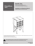
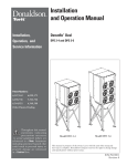
Torit® PowerCore®
CPV-1, -2, -3, -4, -6, -8, and -12 After November 2008
Installation and Operation Manual
Installation, Operation, and Service Information
CPV-1
CPV-2 through CPV-4
CPV-6 through CPV-12
This manual is property of the owner. Leave with the unit when set-up and start-up are complete. Donaldson Company reserves the right to
change design and specifications without prior notice.
Illustrations are for reference only as actual product may vary.
This is the safety alert symbol. It is used to alert you to potential personal injury hazards.
Obey all safety messages that follow this symbol to avoid possible injury or death.
English
Master Language
IOM AD3878002 (ENG)
Revision 6
Donaldson Company, Inc.
APPLICATION OF DUST CONTROL EQUIPMENT
Combustible materials such as buffing lint, paper, wood, metal dusts, weld fume, or flammable coolants or
solvents represent potential fire and/or explosion hazards. Use special care when selecting, installing, and
operating all dust, fume, or mist collection equipment when such combustible materials may be present in
order to protect workers and property from serious injury or damage due to a fire and/or explosion.
Consult and comply with all National and Local Codes related to fire and/or explosion properties of
combustible materials when determining the location and operation of all dust, fume, or mist collection
equipment.
When combustible materials are present you must consult with an expert in fire extinguishing and/or
explosion protection systems, who is also familiar with the local codes, for support and guidance on the
selection and installation of an appropriate fire and/or explosion protection system.
DO NOT allow sparks, cigarettes or other burning objects to enter the hood or duct of any dust, fume, or mist
collection equipment as these may initiate a fire or explosion of any combustible materials accumulated in
the collector.
Portions of dust, mist, and fume-collection equipment, including the clean- and dirty-air plenums may be
considered “OSHA Confined Spaces.” Refer to the appropriate OSHA regulations to determine if a specific
installation should be considered a confined space and if a permit program is required.
Recirculating filtered air in your facility can be a hazard. Consult with OSHA to ensure compliance with all
codes regarding recirculating filtered air.
Improper operation of a dust, fume, or mist control system may contribute to conditions in the work area or
facility that could result in severe personal injury and product or property damage. Check that all dust, fume,
or mist collection equipment is properly selected, installed, and operated for its intended use.
This manual contains specific precautionary statements relative to worker safety. Read this manual thoroughly and
comply as directed. Instruct all personnel on the safe use and maintenance procedures related to this equipment.
Discuss any questions on the application, use, or maintenance of this equipment with a Donaldson Torit representative.
For optimum collector performance, use only Donaldson Torit replacement parts.
Data Sheet
Model Number______________________________ Serial Number_______________________________
Ship Date__________________________________ Installation Date______________________________
Customer Name________________________________________________________________________
Address______________________________________________________________________________
_____________________________________________________________________________________
Filter Type_____________________________________________________________________________
Accessories___________________________________________________________________________
Other_________________________________________________________________________________
Torit PowerCore, CPV-1 to CPV-12
Contents
Description.................................................................................1
Purpose and Intended Use .....................................................1
Rating and Specification Information....................................2
Operation....................................................................................3
Inspection on Arrival................................................................5
Installation Codes and Procedures.......................................5
Installation.................................................................................5
Unit Location..........................................................................5
Rigging Instructions.................................................................6
Hoisting Information.............................................................6
Electrical Wiring.......................................................................6
Standard Equipment.................................................................6
Typical Installation....................................................................7
Compressed Air Installation................................................8
Antistatic Grounding Installation........................................9
Solid-State Timer Installation.................................................9
Solenoid Connection.............................................................9
Timer and Solenoid Specifications.....................................9
Preliminary Start-Up Check..................................................10
Maintenance Information......................................................11
Operational Checklist.........................................................11
Filter Removal and Installation..........................................12
Filter Removal (CPV-1 Only)...............................................12
Filter Installation (CPV-1 Only)..........................................12
Filter Installation..................................................................13
Compressed Air Components............................................14
Electrical Connection (CPV-1 Only)..................................14
Optional Equipment................................................................15
Power Pack (Except CPV-1)..............................................15
Side-Mount Power Pack....................................................16
Magnehelic® Gauge ..........................................................17
Photohelic® Gauge .............................................................18
Delta P Control.....................................................................20
Delta P Plus Control ...........................................................21
Damper Only (CPV-1)..........................................................22
Damper and Silencer, TBI..................................................22
Cold Climate Kit....................................................................22
Troubleshooting.......................................................................24
Service Notes..........................................................................26
Magnehelic® and Photohelic® are registered trademarks of Dwyer Instruments, Inc.
DANGER indicates a hazardous situation which, if not avoided, will result in
death or serious injury.
WARNING indicates a hazardous situation which, if not avoided, could result in
death or serious injury.
CAUTION, used with the safety alert symbol, indicates a hazardous situation
which, if not avoided, could result in minor or moderate injury.
NOTICE
NOTICE is used to address practices not related to personal injury that may
result in damage to equipment.
i
Donaldson Company, Inc.
Description
The Torit PowerCore CPV collector is a continuous duty
dust collector that uses obround style filter packs with
the proprietary axial flow PowerCore filter media. The
system is designed to provide optimum performance for
high efficiency, low operating pressure drop (energy
usage) within a small size collector. The filters can be
pulse-cleaned on- or off-line. Standard sizes range from
1 to 12 obround filter packs.
Purpose and Intended Use
injury.
Misuse or modification of this
equipment may result in personal
Do not misuse or modify.
Discuss the use and application of this equipment with a
Donaldson Torit representative.
In pneumatic conveying systems, Torit PowerCore CPV
can be mounted on the top of silos or storage vessels
to separate the product conveying from displaced air to
prevent product loss and nuisance dust. In mechanical
conveying systems, the dust generated by product
loading, transfer, and discharge can be controlled using
Torit PowerCore CPV on an enclosure. The collected
dust returns directly to the product conveyed making
expensive ductwork systems unnecessary, saving space,
and eliminating dust disposal issues.
Torit PowerCore CPV collectors can be integrated with
process machinery requiring dust control such as fluid
bed reactors, mixers, blenders, mills, and crushers. They
can also be used in bulk materials handling applications
and for bin venting. The CPV model is commonly used in
the grain, chemical, mineral, plastic, wood, composites,
paper, packaging, and textile industries.
Combustible materials such as buffing lint, paper, wood, metal dusts, weld fume, or flammable
coolants or solvents represent potential fire and/or explosion hazards. Use special care when
selecting, installing, and operating all dust, fume, or mist collection equipment when such combustible
materials may be present in order to protect workers and property from serious injury or damage due to a
fire and/or explosion.
Consult and comply with all National and Local Codes related to fire and/or explosion properties of
combustible materials when determining the location and operation of all dust, fume, or mist collection
equipment.
Standard Donaldson Torit equipment is not equipped with fire extinguishing or explosion protection systems.
1
Torit PowerCore, CPV-1 to CPV-12
Rating and Specification Information
Front
Torit PowerCore CPV-1
Front
Torit PowerCore CPV-2 through CPV-4
Front
Torit PowerCore CPV-6 through CPV-12
Typical Side View
Torit PowerCore CPV-1
Typial Side View
Torit PowerCore CPV-2 through CPV-4
Typical Side View
Torit PowerCore CPV-6 through CPV-12
All Units:
Compressed air, maximum psig..................................................................90-100
Housing rating, inches water gauge (CPV-1)............................................. +/-12
Housing rating, inches water gauge (CPV-2 through CPV-12)................ +/-20
Power and controls................................................................... 120-Volt 50/60 Hz
*If unit was supplied with a Record Drawing, the specifications on the drawing will supersede the standard
specifications above.
2
Donaldson Company, Inc.
Operation
During normal operation, dust-laden air enters the
unit through the cabinet opening at the bottom of the
unit, which is fastened to the silo or storage container.
Airflow is directed upwards through the collector. The
CPV filter packs remove fine particulate and clean,
filtered air passes through the CPV filter pack to the
clean-air plenum and discharges through the clean-air
outlet.
3
Filter pack cleaning is completed using pulse-jet
technology. Air diaphragm valves provide the pulse
cleaning. An electronic solenoid valve actuates the pulse
cleaning. Filter packs are easily removed without tools
when they need to be changed.
Torit PowerCore, CPV-1 to CPV-12
High Pressure Air
Clean Air
Outlet
Clean Air
Plenum
Dust Disposal
Dirty Air Inlet
Normal Operation (1 filter pack unit)
Filter Cleaning Operation (1 filter pack unit)
High Pressure Air
Filter Access Door
Clean Air
Plenum
Dirty Air Inlet
Dust Disposal
Clean Air Outlet
Unpowered
Normal Operation (2 to 4 filter pack units)
Filter Cleaning Operation (2 to 4 filter pack units)
High Pressure Air
Filter Access
Door
Clean Air
Plenum
Clean Air
Outlet
Dust Disposal
Dirty Air Inlet
Normal Operation (6 to 12 filter pack units)
Filter Cleaning Operation (6 to 12 filter pack units)
Typical Unit Operation
4
Donaldson Company, Inc.
Inspection on Arrival
1. Inspect unit on delivery.
2. Report any damage to the delivery carrier.
3. Request a written inspection report from the Claims
Inspector to substantiate claim.
4. File claims with the delivery carrier.
5. Compare unit received with description of product
ordered.
6. Report incomplete shipments to the delivery carrier
and your Donaldson Torit representative.
7. Remove crates and shipping straps. Remove loose
components and accessory packages before lifting
unit from truck.
8. Check for hardware that may have loosened during
shipping.
9. Use caution removing temporary covers.
Installation Codes and Procedures
Codes may regulate recirculating
filtered air in your facility.
Consult with the appropriate authorities
having jurisdiction to ensure compliance
with all national and local codes regarding
recirculating filtered air.
Safe and efficient operation of the unit depends on
proper installation.
Authorities with jurisdiction should be consulted
before installing to verify local codes and installation
procedures. In the absence of such codes, install unit
according to the National Electric Code, NFPA No.
70-latest edition.
A qualified installation and service agent must complete
installation and service of this equipment.
All shipping materials, including shipping covers, must be
removed from the unit prior to, or during unit installation.
Failure to remove shipping
materials from the unit will
compromise unit performance.
NOTICE
Inspect unit to ensure all hardware is properly installed
and tight prior to operating collector.
5
Installation
Site selection must account for
wind, seismic zone, and other liveload conditions when selecting the location for
all units.
Codes may regulate acceptable locations for
installing dust collectors. Consult with the
appropriate authorities having jurisdiction to
ensure compliance with all national and local
codes regarding dust collector installation.
The Torit PowerCore CPV is not designed as a "stand
alone" unit. Rather, it is designed to be a filtration/
ventilation component of another component, such
as a silo or bin container. The open bottom of the
Torit PowerCore CPV is intended for roof mounting
applications. Some preparation work may be required
before installing the unit. An opening in the silo or
storage bin must have the correct dimensions and be
properly reinforced to support the weight of the Torit
PowerCore CPV. Reference the Rating and Specification
Information.
Unit Location
Donaldson Torit equipment is not
designed to support site-installed
ducts, interconnecting piping, or electrical
services. All ducts, piping, or electrical
services supplied by others must be adequately
supported to prevent severe personal injury
and/or property damage.
When hazardous conditions or materials are
present, consult with local authorities for the
proper location of the collector.
Locate the collector to ensure easy access to
electrical and compressed-air connections and routine
maintenance.
When outdoor locations are selected, always mount
motors with drain holes pointed down for proper
drainage of moisture.
Torit PowerCore, CPV-1 to CPV-12
Electrical Wiring
Rigging Instructions
Suggested Tools & Equipment
Clevis Pins and Clamps
Crane or Forklift
Drift Pins
Drill and Drill Bits
Open End Wrenches
Large Crescent Wrench
Lifting Slings
Pipe Sealant
Pipe Wrenches
Screwdrivers
Socket Wrenches
Spreader Bars
Hoisting Information
Failure to lift the collector
correctly can result in severe
personal injury or property damage.
Do not lift unit by the door handle or air
manifold. Follow IOM guidelines and
illustrations.
Use appropriate lifting equipment and adopt
all safety precautions needed for moving and
handling the equipment.
A crane or forklift is recommended for
unloading, assembly, and installation of the
collector.
Location must be clear of all obstructions, such
as utility lines or roof overhang.
Use all lifting points provided.
Use clevis connectors, not hooks, on lifting slings.
Use spreader bars to prevent damage to unit’s casing.
Check the Specification Control drawing for weight
and dimensions of the unit and components to ensure
adequate crane capacity.
Electrical service or maintenance
work must be performed by
a qualified electrician and comply with all
applicable national and local codes.
Turn power off and lock out electrical
power sources before performing service or
maintenance work.
Do not install in classified hazardous
atmospheres without an enclosure rated for
the application.
All electrical wiring and connections, including electrical
grounding, should be made in accordance with the
National Electric Code, NFPA No. 70-latest edition.
Check local ordinances for additional requirements that
apply.
The appropriate wiring schematic and electrical rating
must be used. See unit’s rating plate for required voltage.
If the unit is not furnished with a factory-mounted
disconnect, an electric disconnect switch having
adequate amp capacity shall be installed in accordance
with Part IX, Article 430 of the National Electrical Code,
NFPA No. 70-latest edition. Check unit’s rating plate for
voltage and amperage ratings.
Refer to the wiring diagram for the number of wires
required for main power wiring and remote wiring.
Standard Equipment
Standard installation consists of base unit, electrical, and
compressed air connections.
Allow only qualified crane operators to lift the equipment.
Refer to applicable OSHA regulations and local codes
when using cranes, forklifts, and other lifting equipment.
Lift unit and accessories separately, and assemble after
unit is in place.
6
Donaldson Company, Inc.
Typical Installation
CPV-1
angle not to exceed
30° from vertical
Latches and
manifold are
not lifting
points
30
CPV-2 through CPV-4
Do not lift with
this orientation
CPV-6 through CPV-12
Manifolds are
not lifting points
Take center of gravity into consideration
when lifting unit.
Do not install blower before lifting unit (except CPV-1).
Typical Installation
7
0'
Latches are not lifting points
Torit PowerCore, CPV-1 to CPV-12
Compressed Air Installation
Do not set compressed-air
pressure above 100-psig.
Component damage can occur.
NOTICE
Turn compressed air supply OFF
and bleed lines before performing
service or maintenance work.
All compressed air components must be sized
to meet the maximum system requirements of
90-psig supply pressure.
A safety exhaust valve should be used to
isolate the compressed air supply. The safety
exhaust valve should completely exhaust
downstream pressure when closed and include
provisions to allow closed-position locking.
The compressed-air supply must be oil
and moisture free. Contamination in the
compressed air used to clean filters will result
in poor cleaning, cleaning valve failure or poor
collector performance.
Purge compressed-air lines to remove debris
before connecting to the unit’s compressed-air
manifold.
1. Remove the plastic pipe plug from the unit's air
manifold and connect the compressed-air supply
line. Use thread-sealing tape or pipe sealant on all
compressed air connections and fittings.
2. Install a customer-supplied shut-off valve, bleedtype regulator with gauge, filter, and automatic
condensate valve in the compressed-air supply line.
3. Set compressed-air supply between 90-100-psig. The
pulse-cleaning controls are factory set to clean one
filter every 10-seconds during a cleaning cycle.
air
regulator*
bleed-type
air filter* safety exhaust valve*
automatic
condensate
valve*
compressed-air
supply*
*customer supplied
Compressed Air Installation
8
Donaldson Company, Inc.
Antistatic Grounding Installation
If the collector is equipped with antistatic filters and
bonded construction, then the collector will need to be
grounded by a qualified electrician.
pressure reaches the high-pressure setpoint. The
valves continue to pulse until the low-pressure
setpoint is reached.
1. Follow the instructions provided by the antistatic
grounding drawing provided.
NOTICE
2. Ground the collector using the grounding lug at the
rear of the collector.
3. Take resistance readings from the filter media to
ground to ensure conductivity. Records results as
indicated on the drawing.
Solid-State Timer Installation
Electrical service or maintenance
work must be performed by
a qualified electrician and comply with all
applicable national and local codes.
Turn power off and lock out electrical power
sources before performing installation, service,
or maintenance work.
Do not install in classified hazardous
atmospheres without an enclosure rated for
the application.
The solid-state timer is an electronic timer used to
control the filter cleaning system. Available options
include 3, 6, 10, 20, and 32-pin solenoid valve control.
1. Using the supplied wiring diagram, wire the fan
motor, fan-motor starter, solid-state timer, and
solenoid valves. Use appropriate wire gauge for
rated amp load as specified by local codes.
2. Plug the program lug into the pin that corresponds
with the number of solenoid valves controlled.
3. With power supply ON, check the operation of the
solenoid valves. The valves should open and close
sequentially at factory set 10-second intervals.
4. If a Photohelic gauge or similar device is used to
control the solid-state timer and the jumper on the
pressure switch portion of the timer is removed,
the solenoid valves pulse only when the differential
9
The solid-state timer voltage must
match the voltage of the rating of
the timer provided (typically 115VAC).
Do not mount the solid-state timer directly to
the unit. Mechanical vibration can damage the
control.
Solenoid Connection
The unit is equipped with 115-V solenoid valves that
control the pulse-cleaning valves, which clean the filters.
One of three types of solenoid enclosures, the
weatherproof NEMA 4 with 3D2 solenoids, the explosion
proof NEMA 7 with 5D2 solenoids, or the explosion proof
NEMA 9 with 5D2 solenoids, is mounted near or on the
unit’s compressed-air manifold.
Wire the solenoids to the solid-state timer following
the wiring diagram supplied with the unit. Filter life and
cleaning operation will be affected if not wired correctly.
Timer and Solenoid Specifications
Power to the solid-state timer is supplied to Terminals L1
and L2, which operate in parallel with the fan starter’s
low-voltage coil. On fan start-up, power is supplied to
the timer and the preset OFF time is initiated. At the end
of the OFF time, the timer energizes the corresponding
solenoid valve to provide the ON time cleaning pulse for
one diaphragm valve and then steps to the next until all
filters have been cleaned.
To pulse when the fan is OFF, install a toggle switch as
shown on the Solid-State Timer Wiring Diagram. When
the toggle switch is ON, the timer receives power and
energizes the solenoid valves’ pulse-cleaning operation
even though the fan is turned OFF.
Torit PowerCore, CPV-1 to CPV-12
Preliminary Start-Up Check
Instruct all personnel on safe use and maintenance
procedures.
Input
Electrical work during installation
must be performed by a qualified
electrician and comply with all applicable
national and local codes.
105-135V/50-60Hz/1Ph
Output Solenoids
The load is carried and turned ON and OFF by the 200
watt maximum-load-per-output solid-state switch.
Turn power off and lock out electrical
power sources before performing service or
maintenance work.
Pulse ON Time
Factory set at 100-milliseconds, or 1/10-second.
Turn compressed air supply OFF and bleed
lines before performing service or maintenance
work.
Do not adjust pulse ON time
NOTICE
unless the proper test equipment
is available. Too much or too little ON time can
cause shortened filter life.
Check that the collector is clear and free of all
debris before starting.
Pulse OFF Time
Do not install in classified hazardous
atmospheres without an enclosure rated for
the application.
Factory set at 10-seconds, adjustable from 1 to
1.5-second minimum to maximum 60 to 66-second.
Operating Temperature Range
Optional fans over 600 lbs must be
independently supported.
-20° F to 130° F
Transient Voltage Protection
50 kW transient volts for 20-millisecond duration once
every 20 seconds, 1% duty cycle.
Solenoid Valves
115-V at 19.7 watts each
1. Check all electrical connections for tightness and
contact.
2. Motor and fan should be wired for clockwise rotation
when viewed from the back of the motor.
To reverse rotation, single-phase power supply:
Follow manufacturer’s instructions on the motor’s
nameplate.
To reverse rotation, three-phase power supply:
Turn electrical power OFF at source and switch any
two leads on the motor junction box.
Compressed-Air
Set compressed-air supply at 90-psig. The timer is
factory set to clean one filter or set of filters every
10-seconds.
Do not increase supply pressure
above 100-psig. Component
damage can occur.
NOTICE
Do not interchange a power lead
with the ground wire. Severe
personal injury or equipment damage may result.
10
Donaldson Company, Inc.
Do not set compressed-air
pressure above 100-psig.
Component damage can occur.
3. Check that filter retention brackets are properly
tightened to achieve proper filter seal.
NOTICE
4. All access panels should be sealed and secure.
All compressed air components must be sized
to meet the maximum system requirements of
90-100 psi.
5. Check that exhaust damper is set to the fully-closed
position.
6. Check and remove all loose items in or near the inlet
and outlet of the unit.
The compressed-air supply must be oil
and moisture free. Contamination in the
compressed air used to clean filters will result
in poor cleaning, cleaning valve failure, or poor
collector performance.
7. Check that all remote controls and solenoid
enclosures (if applicable) are properly wired and all
service switches are in the OFF position.
Purge compressed air lines to remove debris
before connecting to the unit's compressed air
manifold.
8. Check that all optional accessories are installed
properly and secured.
9. Turn power ON at source.
10. Turn the compressed-air supply ON. Adjust pressure
regulator for 90-100 psig.
Operational Checklist
11. Turn blower fan motor ON.
1. Monitor the physical condition of the collector and
repair or replace any damaged components.
12. Adjust airflow with the exhaust damper, if equipped.
Routine inspections will minimize downtime and
maintain optimum system performance. This
is particularly important on continuous-duty
applications.
Periodically check the compressed air components
and replace compressed air filters. Drain moisture
following the manufacturer's instructions. With
the compressed air supply ON, check the cleaning
valves, solenoid valves, and tubing for leaks. Replace
as necessary.
Excess airflow can shorten filter
life, cause electrical system
failure, and blower motor failure.
NOTICE
Maintenance Information
Instruct all personnel on safe use and maintenance
procedures.
Use proper equipment and adopt
all safety precautions needed
for servicing equipment. Electrical service
or maintenance work must be performed by
a qualified electrician and comply with all
applicable national and local codes.
Turn power off and lock out electrical
power sources before performing service or
maintenance work.
Do not install in classified hazardous
atmospheres without an enclosure rated for the
application.
Turn compressed air supply OFF and bleed
lines before performing service or maintenance
work.
11
2. Monitor pressure drop across filters.
Abnormal changes in pressure drop indicate a
change in operating conditions and possibly a fault
to be corrected. For example, prolonged lack of
compressed air will cause an excess build-up of dust
on the filters resulting in increased pressure drop.
Cleaning off-line with no flow usually restores the
filters to normal pressure drop.
3. Monitor exhaust.
4. Monitor dust disposal.
Torit PowerCore, CPV-1 to CPV-12
Filter Removal and Installation
Use proper safety and protective
equipment when removing
contaminants and filters.
3. Lift left side of retainer up while moving the right side
towards the back wall.
Dirty filters may be heavier than they appear.
4. Pull the raised left side of the retainer through upper
left of opening.
Use care when removing filters to avoid
personal injury.
5. Remove pack vertically until clear of tubesheet.
Filter Installation (CPV-1 Only)
Filter Removal (CPV-1 Only)
When inserting the filter pack,
start at the back edge of the pack
first to ensure alignment tabs do not damage
the filter packs.
1. Turn power to unit OFF.
2. Loosen wing nuts and slide filter retainer left to
release from hold down.
1. Insert the filter pack, starting with the back edge
first, to ensure alignment tabs do not damage filter
pack.
2. Slide the right side of the retainer through lower right
of opening.
3. Lower the right side of retainer while moving the left
side toward the back wall.
3
2
1
Filter Retainer Removal (hinged access panel removed for clarity)
Filter Removal and Installation
(hinged access panel removed for clarity)
Filter Removal and Installation for CPV-1 Units
12
Donaldson Company, Inc.
4. Slide filter retainer right and under the hold down lip.
5. Position wing nuts over studs and tighten until stops
are in contact with tubesheet.
Filter Removal (except CPV-1)
1. Turn power to unit OFF.
2. Open access door by releasing locking mechanism.
Swing door fully open. Prevent door from closing by
engaging door locking mechanism (except CPV-1).
3. Turn filter pack retention wing nuts counterclockwise
and remove filter pack retainer. Removal of back
row of filter packs first is recommended.
4. Remove filter pack by lifting straight up.
3. Insert filter pack retainer by engaging both rear
tabs of the retainer into the slots located just behind
the filter pack opening, or on opposite side of the
threaded studs, then align the filter pack retention
wing nuts over the posts.
4. Turn filter pack retention wing nuts clockwise until
filter pack gasket is fully seated.
5. Repeat steps 2 through 4 for remaining filter packs.
6. Disengage door locking mechanism (except CPV-1).
Use caution when closing door to avoid personal
injury.
7. Turn access door latch to lock.
5. Repeat steps 1-4 to remove remaining filter packs.
8. Reset exhaust damper to required setting if so
equipped.
Filter Installation
9. Turn electrical power and compressed air supply ON
before starting unit.
1. Clean the surface around the filter opening where
the gasket is seated to ensure a good seal.
2. Insert first filter pack into the tubesheet. Installing
front row of filter packs first is recommended.
filter pack retainer
filter pack
Filter Removal and Installation
13
Torit PowerCore, CPV-1 to CPV-12
Compressed Air Components
Electrical Connection (CPV-1 Only)
Electrical work must be
performed by a qualified
electrician and comply with all applicable
national and local codes.
Do not set compressed-air
pressure above 100-psig.
Component damage can occur.
NOTICE
1. Periodically check the compressed air components
and replace compressed-air filter.
Turn power off and lock out electrical
power sources before performing service or
maintenance work.
2. Drain moisture following the manufacturer’s
instructions.
3. With the compressed-air supply ON, check the
cleaning valves, solenoid valves, and tubing for
leaks. Replace as necessary.
Do not install in classified hazardous
atmospheres without an enclosure rated for
the application.
1. Using the wiring diagram supplied, wire the
customer-supplied disconnect switch and fan
starter. Make the connections to the fan motor.
Use appropriate wire gauge for rated amp load as
specified by local codes.
2. Turn the fan motor On then OFF to check for proper
rotation by referencing the rotation arrow located on
the motor's mounting plate.
Do not look into fan outlet to
determine rotation. View the fan
rotation from the back of the motor.
Check that the exhaust plenum is free of tools
or debris before checking blower/fan rotation.
Stand clear of exhaust to avoid personal injury.
To reverse rotation, three-phase power supply: Turn
electrical power OFF at source and switch any two
leads on the output-side of the fan motor starter.
Do not interchange a power lead
with the ground wire. Severe
personal injury or equipment damage may
result.
14
Donaldson Company, Inc.
Optional Equipment
Power Pack (Except CPV-1)
The two types of power packs, Torit Backward Inclined
(TBI) and Torit Radial Blade (TRB) are installed following
similar procedures.
1. Power packs are shipped assembled and partial
disassembly is required before installing.
Do not allow the fan wheel to
come loose from the motor as it
may cause severe injury or property damage.
To ensure proper attachment of the fan wheel:
Tighten all set screws in fan wheel.*
2. Remove eight motor-mount bracket fasteners;
remove the motor, motor-mount bracket, and fan
wheel as an assembly.
Tighten all set screws in bearings.*
3. Turn housing over and apply sealant to the outside
edge of the bolt pattern on the fan housing. Mount
the fan housing to the collector using the inlet cone
fasteners.
Reference Wheel Set Screw Torque Table.
4. Apply sealant to the outside edge of the bolt pattern
on the fan housing. Reinstall the motor, bracket, and
fan wheel assembly. Align motor mount bracket to
the mark on the housing on 30 Hp/60 Hz, and 20-30
Hp/50 Hz units. Other motor sizes do not require
alignment, but consider the electrical connection
location.
5. Rotate fan wheel after installation to ensure proper
clearance between the inlet cone and the fan wheel.
Do not look into fan outlet to
determine rotation. View the fan
rotation from the back of the motor.
Check that the exhaust plenum is free of tools
or debris before checking blower/fan rotation.
Stand clear of exhaust to avoid personal injury.
To reverse rotation, three-phase power supply: Turn
electrical power OFF at source and switch any two
leads on the output-side of the fan motor starter.
Do not interchange a power lead
with the ground wire. Severe
personal injury or equipment damage may
result.
15
Repeat after 8 hours of operation.
Repeat again after two weeks of operation.
Setscrew Size
Diameter
Carbon Steel Setscrew
Torque*
In.
Lb. - In.
Lb. - Ft.
1/4
75
6.2
5/16
144
12
3/8
252
21
7/16
396
33
1/2
600
50
5/8
1164
97
3/4
2016
168
7/8
3204
267
1
4800
400
*Stainless steel setscrews are not hardened and
should not be tightened to more than half of the values
shown.
Wheel Set Screw Torque
Torit PowerCore, CPV-1 to CPV-12
Side-Mount Power Pack
Do not look into fan outlet to
determine rotation. View the fan
rotation from the back of the motor.
Electrical service or maintenance
work must be performed by
a qualified electrician and comply with all
applicable national and local codes.
Turn power off and lock out electrical
power sources before performing service or
maintenance work.
Do not install in classified hazardous
atmospheres without an enclosure rated for
the application.
Mounting a power pack on the
side of a collector requires a
power pack adapter to support the weight of
the power pack.
Check that the exhaust plenum is free of tools
or debris before checking blower/fan rotation.
Stand clear of exhaust to avoid personal injury.
To reverse rotation, three-phase power supply: Turn
electrical power OFF at source and switch any two
leads on the output-side of the fan motor starter.
Do not interchange a power lead
with the ground wire. Severe
personal injury or equipment damage may
result.
Poorly installed power packs may separate
from the collector resulting in personal injury
and damage to equipment or property.
1. Disconnect power supply.
2. Apply 1/4-in diameter rope-type sealant to the
outside surface of the power pack adapter between
the fan mount bolt holes and the round fan inlet hole.
3. Install the fan housing to the power pack adapter
using 3/8 x 1 1/4-in bolts, flat washers, and hex nuts.
Install bolts with the bolt head in
NOTICE
the fan housing and the threaded
end in the power pack adapter.
power pack adapter
CPV-2, -3, or -4 Side Mount Power Pack
4. Reinstall the motor, bracket, and fan wheel assembly.
Align motor mount bracket to the mark on the
housing on 30 Hp/60 Hz and 20-30 Hp/50 Hz units.
Other motor sizes do not require alignment, but
consider the electrical connection location.
5. Connect power supply to the motor. Turn the fan
motor ON then OFF to check motor rotation by
referencing the rotation arrow on the blower.
To change rotation on three
phase units, turn power supply
OFF and switch any two leads on the output
side of the fan motor starter.
NOTICE
power pack adapter
CPV-6, -8, or -12 Side Mount Power Pack
16
Donaldson Company, Inc.
Magnehelic® Gauge
The Magnehelic is a differential pressure gauge used
to measure the pressure difference between the cleanair and dirty-air plenums and provides a visual display
of filter change requirements. The high-pressure tap is
located in the dirty-air plenum and the low-pressure tap
is located in the clean-air plenum.
3. Attach the mounting bracket using three, #6-32 x 1/4in screws supplied.
4. Mount the gauge and bracket assembly to the
supporting structure using two, self-drilling screws.
1. Choose a convenient, accessible location on or near
the unit for mounting that provides the best visual
advantage.
2. Plug the pressure ports on the back of the gauge
using two, 1/8-in NPT pipe plugs supplied. Install two,
1/8-in NPT male adapters supplied with the gauge
into the high- and low-pressure ports on the side of
the gauge.
clean-air plenum pressure
tap location
5. Thirty-five feet of plastic tubing is supplied and must
be cut in two sections. Connect one section of tubing
from the gauge’s high-pressure port to the pressure
fitting located in the dirty-air plenum. Connect
remaining tubing from the gauge’s low-pressure
port to the fitting in the clean-air plenum. Additional
tubing can be ordered from your representative.
6. Zero and maintain the gauge as directed in the
manufacturer’s Operating and Maintenance
Instructions provided.
1/8-in NPT adapter
plenum tap location
3/8-in flat washer
1/8-in NPT x 90°
male elbow
Magnehelic gauge
high-pressure port
low-pressure port
1/8-in NPT coupling
two, 1/8-in NPT
adapters
plastic tubing
two, 1/8-in NPT pipe plugs
support structure
mounting surface
two, self-drilling screws
1/8-in NPT x 90° male elbow
#6-32 x 1/4-in mounting screws
mounting bracket
1/8-in NPT adapter
dirty-air plenum pressure tap location
3/8-in flat washer
1/8-in NPT adapter
1/8-in NPT x 90° elbow
static pressure tee
Magnehelic Gauge Installation
17
Torit PowerCore, CPV-1 to CPV-12
Photohelic® Gauge
Electrical service or maintenance
work must be performed by
a qualified electrician and comply with all
applicable national and local codes.
Turn power off and lock out electrical
power sources before performing service or
maintenance work.
Do not install in classified hazardous
atmospheres without an enclosure rated for
the application.
The Photohelic combines the functions of a differential
pressure gauge and a pressure-based switch. The gauge
function measures the pressure difference between the
clean-air and dirty-air plenums and provides a visual
display of filter condition. The high-pressure tap is
located in the dirty-air plenum and a low-pressure tap
is located in the clean-air plenum. The pressure-based
switch function provides high-pressure ON and lowpressure OFF control of the filter cleaning system.
2. Mount the gauge to the remote panel or door using
the mounting ring, retaining ring, and four #6-32 x 1
1/4-in screws. Do not tighten screws. Connect two,
1/8-in NPT x 1/4-in OD male adapters to the gauge’s
high- and low-pressure ports. Tighten screws.
3. On the back of the gauge, remove four #6-32 x 5/16-in
screws and plastic enclosure. Set aside. Add two
jumper wires supplied by customer. Remove the
jumper from the pressure switch located on the timer
board, if equipped. Using the 3/4-in conduit opening,
wire the gauge as shown. Reassemble and fasten
enclosure securely.
4. Thirty-five feet of plastic tubing is supplied and must
be cut in two sections. Connect one section of tubing
from the gauge’s high-pressure port to the pressure
fitting located in the dirty-air plenum. Connect
remaining tubing from the gauge’s low-pressure
port to the fitting in the clean-air plenum. Additional
tubing can be ordered from your representative.
1. Choose a convenient, accessible location on or near
the unit for mounting that provides the best visual
advantage.
jumper wires
supplied by customer
Photohelic gauge
LO
HI
C
NO NC NC NO C
C
NO NC NC NO C
L1
L2
solenoid
valves
Pressure Switch
terminals
timer
board
sol
com
L1 L2
1
2 3
neutral
110-V
Note:
For use with solid-state timer only. All parts, except
the mounting bracket shown in the Photohelic Gauge
Standard Installation drawing are included with the
NEMA 4, Weatherproof Enclosure.
Photohelic Gauge in Optional NEMA 4 Weatherproof
Enclosure
Photohelic Gauge Wiring Diagram
18
Donaldson Company, Inc.
5. Zero and maintain the gauge as directed in the
manufacturer’s Operating and Maintenance
Instructions provided.
6. To install the Photohelic Gauge mounted in a NEMA
4, Weatherproof Enclosure, follow Steps 4 and 5.
NPT male adapter
1/8-in NPT male
adapter
Photohelic gauge
high-pressure port
low-pressure port
two 1/8-in NPT adapters
clean air plenum
pressure tap location
plastic tubing
1/8-in NPT male adapter
dirty air plenum pressure
tap location
static pressure tee
Photohelic Gauge, Remote Panel or Door Installation
19
Torit PowerCore, CPV-1 to CPV-12
Delta P Control
Description
The Delta P Controller monitors the differential pressure
between the clean and dirty air plenums, providing a
visual display of the filter condition. When combined with
a pulse timer, it controls the pressure drop by turning
the cleaning mechanism On and Off at the chosen limits.
There are three (3) set points: High Pressure On, Low
Pressure Off, and Alarm. The first two, High Pressure On
and Low Pressure Off, control the filter cleaning system.
The third, Alarm, provides a relay output to activate an
external alarm supplied by others.
Operation
Alarm
The Alarm setpoint is set to a higher setting than the High
Pressure On setpoint used to start the filter cleaning
cycle. It indicates situations when the cleaning system
cannot reduce the pressure drop due to cleaning system
failure, lack of compressed air, or the end of the filter's
useful life. There is a time delay prior to setting the Alarm
to prevent nuisance trips. The Delta P Controller also
provides an input connection for a remote alarm reset.
For complete information, see the most current version
of the Delta P Installation, Operation, and Maintenance
manual.
Normal
The Delta P Controller monitors the pressure in the
clean and dirty air plenums while the unit is running. The
blower draws air through the filters, creating a pressure
drop. The Delta P Controller measures the pressure drop
and provides a visual display in inches water gauge or
metric (SI) units of daPa.
Filter Cleaning
When the pressure drop across the filters reaches the
High Pressure On setpoint, the controller closes an
output relay allowing a timer to trigger the cleaning
valves sequentially. When the controller senses that the
pressure drop has decreased to the Low Pressure Off
setpoint, the relay opens and the cleaning cycle stops.
This sequence continues as long as the collector is
in use, maintaining the pressure drop within a narrow
range.
Delta P Control Display
20
Donaldson Company, Inc.
Delta P Plus Control
Description
The Delta P Plus Controller monitors the differential
pressure between the clean and dirty air plenums,
providing a visual display of the filter condition. When
combined with a pulse timer, it controls the pressure
drop by turning the cleaning mechanism on and Off at
the chosen limits. There are three (3) set points: High
Pressure On, Low pressure Off, and Alarm. The first two,
High Pressure On and Low Pressure Off, control the
filter cleaning system. The third, Alarm, provides a relay
output to activate an external alarm supplied by others.
The user can program the Delta P Plus Controller to
pulse while the collector is running, to maintain a
relatively constant pressure drop across the filters, pulse
only after the collector is shut down (after-shift cleaning),
or a combination of both, cleaning while running as well
as end of the shift.
Operation
Normal
The Delta P Plus Controller monitors the pressure on
both sides of the tubesheet while the unit is running.
As air flows through the filters, the resistance of the
media and collected dust creates a pressure difference
or "drop" between the dirty and clean air plenums. The
Delta P Plus Controller measures the pressure drop and
provides a visual display in inches water gauge or metric
(SI) units of daPa.
the pressure drop exceeds the Low Pressure Off set
point and then approaches zero again, the Delta P
Plus Controller runs a delay timer to allow the blower
to come to a stop and then engages the cleaning
mechanism for a preselected time.
3. Combined Differential and Downtime Cleaning
(ALL) - The Delta P Plus Controller combines the two
functions described above; maintaining the pressure
drop in a narrow band and downtime cleaning
the filters when the collector is shut down. The
downtime cleaning function can be toggled On or Off
from the keyboard.
Alarm
The Alarm setpoint is set to a higher setting than the
High Pressure On used to start the filter cleaning cycle.
It indicates situations when the cleaning system cannot
reduce the pressure drop due to cleaning system failure,
lack of compressed air, or the end of the filter's useful
life. There is a time delay prior to setting the Alarm to
prevent nuisance trips. The Delta P Plus Controller also
provides an input connection for a remote Alarm reset.
For complete information, see the most current version of
the Delta P Plus Installation, Operation, and Maintenance
manual.
Filter Cleaning
The Delta P Plus Controller offers three filter cleaning
options.
1. Differential Pressure Cleaning (DFF) - When the
pressure drop across the filters reaches the
Controller's High Pressure On setpoint, the Controller
closes an output relay allowing a sequential timer
to trigger the cleaning valves. When the Controller
senses that the pressure drop has decreased to
the Low Pressure Off setpoint, the relay opens and
the cleaning cycle stops. This sequence continues
as long as the collector is in use, maintaining the
pressure drop within a narrow range.
2. Downtime Cleaning (DTC) - The Delta P Plus
Controller monitors the collection system. When
21
Delta P Plus Control Display
Torit PowerCore, CPV-1 to CPV-12
Damper Only (CPV-1)
Side Mount
1. Attach the damper to the fan exhaust outlet using the
hardware supplied.
2. Loosen the wing nut on the damper and adjust from
30 to 50% closed.
Damper and Silencer, TBI
b. Drill pilot holes with a 0.339-in bit.
c. Secure brackets using 3/8-in thread-forming
bolts.
6. Loosen the wing nut on the damper and adjust from
30 to 50% closed.
Cold Climate Kit
Side Mount
1. Install the power pack as described in the previous
section.
2. Attach the damper to the fan exhaust outlet using the
hardware supplied.
3. Attach the flange to the damper using the bolts,
washers, and hex nuts supplied.
4. Apply sealant to the flange and attach silencer to
flange. Tighten all hardware.
5. Loosely assemble the silencer’s support brackets.
a. Align the support bracket to the underside of the
silencer, flush with the cabinet wall and mark the
drill locations.
power pack
damper
Electrical service or
maintenance work during
installation must be performed by a qualified
electrician and comply with all applicable
national and local codes.
Turn power off and lock out electrical
power sources before performing service or
maintenance work.
A cold climate kit provides heat to the pulse valves to
prevent cold weather freeze up. The basic kit, for use in
applications that have a moderate amount of moisture
in the compressed-air supply, consists of a small
heating element and thermostat installed in the solenoid
enclosure. The basic kit is factory-installed and supplied
with the appropriate solenoid wiring instructions.
exhaust silencer
support bracket
Side Mount Silencer and Damper Installation
22
Donaldson Company, Inc.
A heavy-duty kit is available for applications that
have moderate-to-high amounts of moisture in the
compressed-air supply and consists of the basic kit plus
a heat cable to deliver heat to the large pulse valves.
This kit is customer-installed and detailed installation
instructions are provided.
6. Secure junction box to manifold using two, 8-in hose
clamps wrapped around the standoff.
7. Wrap 6-ft of pipe insulation tape around each heatcable wrapped valve. Wrap the entire valve, double
wrapping the hose-clamped heat cable. Secure with
cable ties.
1. Install the power connection kit on the heat cable
following the manufacturer’s instructions.
2. Start with the upper right-hand valve, wrap heat
cable around the valve as shown in
Detail A. Pull heat cable tight.
2
Double wrap between round
coupling and square valve cover.
NOTICE
1
start here
3. Position a 3-in hose clamp around the double
wrapped heat cable and tighten securely.
4. Wrap remaining valves using the same technique in
the order shown in Detail B.
5. Drill a 1-in diameter hole in the back of the junction
box. See Detail C. Assemble the power connection
kit following the manufacturer’s instructions.
4
3
4-Valve Configuration
Cold Climate Kit, Detail B
Step 2
double
wrap
Step 3
3-in hose
clamp
Cold Climate Kit, Detail A
23
Cold Climate Kit, Detail C
Torit PowerCore, CPV-1 to CPV-12
Troubleshooting
Problem
Probable Cause
Remedy
Power pack/fan motor do
not start
Improper motor wire size
Rewire using the correct wire gauge as specified by
national and local codes.
Check and correct motor wiring for supply voltage.
See motor manufacturer's wiring diagram. Follow
wiring diagram and the National Electric Code.
Correct wiring for proper supply voltage.
Not wired correctly
Unit not wired for available
voltage
Input circuit down
Electrical supply circuit down
Power pack/fan motor
start, but do not stay
running
Check power supply to motor circuit on all leads.
Check power supply circuit for proper voltage.
Check for fuse or circuit breaker fault. Replace as
necessary.
Incorrect motor starter installed Check for proper motor starter and replace if
necessary.
Access doors are open or not
closed tight
Damper control not adjusted
properly
Electrical circuit overload
Clean-air outlet
discharging dust
Insufficient airflow
Filter packs not installed
correctly
Filter pack damage, gasket
damage, or holes in media
Fan rotation backwards
Access doors open or not
closed tight
Fan exhaust area restricted
Close and tighten access doors. See Filter
Replacement.
Check airflow in duct. Adjust damper control until
proper airflow is achieved and the blower motor’s
amp draw is within the manufacturer’s rated amps.
Check that the power supply circuit has sufficient
power to run all equipment.
See Filter Replacement.
Replace filter packs as necessary. Use only
genuine Donaldson replacement parts. See Filter
Replacement.
Proper fan rotation is clockwise from the top of the
unit. The fan can be viewed from the back of the
motor. See Preliminary Start-Up Check.
Check that all access doors are in place and
secured. Check that the hopper discharge opening is
sealed and that dust container is installed correctly.
Check fan exhaust area for obstructions. Remove
material or debris. Adjust damper flow control.
Filter packs need replacement
Remove and replace using genuine Donaldson
replacement filter packs. See Filter Replacement.
Lack of compressed air
See Rating and Specification Information for
compressed air supply requirements.
24
Donaldson Company, Inc.
Troubleshooting
Problem
Probable Cause
Remedy
Insufficient airflow
continued
Pulse cleaning not energized
Use a voltmeter to check the solenoid valves in the
control panel. Check pneumatic lines for kinks or
obstructions.
Lock out all electrical power to the unit and bleed
the compressed air supply. Check for debris, valve
wear, pneumatic tubing fault, or diaphragm failure by
removing the diaphragm cover on the pulse valves.
Check for solenoid leaks or damage. If pulse valves
or solenoid valves and tubing are damaged, replace.
Use a voltmeter to check for supply voltage.
Pulse valves leaking
compressed air
No display on the Delta P
Controller
No power to the controller
Fuse blown
Display on Delta P
Controller does not read
zero when at rest
Delta P Controller ON, but
cleaning system does not
start
Out of calibration
Pressure tubing disconnected,
ruptured, or plugged
Check the fuse in the control panel. See wiring
diagram inside the control panel. Replace if
necessary.
Recalibrate as described in Delta P Maintenance
Manual
Check tubing for kinks, breaks, contamination, or
loose connections.
High Pressure On or Low
Pressure Off setpoint not
adjusted for system conditions
Pulse cleaning never stops Pressure switch not operating
correctly
Adjust setpoints to current conditions.
High Pressure On or Low
Pressure Off setpoint not
adjusted for system conditions
Pressure tubing disconnected,
ruptured, plugged, or kinked
Adjust setpoints to current conditions.
Alarm setpoint too low
Adjust to a higher value.
Excess pressure drop
Check cleaning system and compressed air supply.
Replace filter packs if filter packs do not clean down.
Pressure tubing disconnected,
ruptured, plugged, or kinked
Check tubing for kinks, breaks, contamination, or
loose connections.
Improper operation
Press and hold one of the three setpoint keys to use
arrow keys.
Alarm light is ON
Delta P Controller arrow
keys to not work
25
Check pressure switch inside the control panel.
Check tubing for kinks, breaks, contamination, or
loose connections.
Torit PowerCore, CPV-1 to CPV-12
Service Notes
Date
Service Performed
Notes
26
Donaldson Company, Inc.
Service Notes
Date
27
Service Performed
Notes
The Donaldson Torit Warranty
Donaldson warrants to the original purchaser that the major structural components of the goods will be free
from defects in materials and workmanship for ten (10) years from the date of shipment, if properly installed,
maintained and operated under normal conditions. Donaldson warrants all other Donaldson built components
and accessories including Donaldson Airlocks, TBI Fans, TRB Fans, Fume Collector products, Donaldson
built electrical control components and Donaldson built Afterfilter housings for twelve (12) months from date
of shipment. Donaldson warrants Donaldson built filter elements to be free from defects in materials and
workmanship for eighteen (18) months from date of shipment. Donaldson does not warrant against damages due
to corrosion, abrasion, normal wear and tear, product modification, or product misapplication. Donaldson also
makes no warranty whatsoever as to any goods manufactured or supplied by others including electric motors,
fans and control components. After Donaldson has been given adequate opportunity to remedy any defects in
material or workmanship, Donaldson retains the sole option to accept return of the goods, with freight paid by the
purchaser, and to refund the purchase price for the goods after confirming the goods are returned undamaged
and in usable condition. Such a refund will be in the full extent of Donaldson’s liability. Donaldson shall not be
liable for any other costs, expenses or damages whether direct, indirect, special, incidental, consequential
or otherwise. The terms of this warranty may be modified only by a special warranty document signed by a
Director, General Manager or Vice President of Donaldson. Failure to use genuine Donaldson replacement
parts may void this warranty. THERE EXIST NO OTHER REPRESENTATIONS, WARRANTIES OR GUARANTEES
EXCEPT AS STATED IN THIS PARAGRAPH AND ALL OTHER WARRANTIES INCLUDING MERCHANTABILITY
AND FITNESS FOR A PARTICULAR PURPOSE, WHETHER EXPRESS OR IMPLIED ARE HEREBY EXPRESSLY
EXCLUDED AND DISCLAIMED.
Parts and Service
For genuine Donaldson replacement filters and parts, call the Parts Express Line. For faster service,
have unit’s model and serial number, quantity, part number, and description available.
Donaldson Company, Inc.
Torit
P.O. Box 1299
Minneapolis, MN 55440-1299
[email protected]
800-365-1331 USA
800-343-3936 within Mexico
www.donaldsontorit.com
Donaldson Company, Inc. is the leading designer and manufacturer of dust, mist, and fume collection
equipment used to control industrial-air pollutants. Our equipment is designed to help reduce
occupational hazards, lengthen machine life, reduce in-plant maintenance requirements, and
improve product quality.
© 2008 Donaldson Company, Inc. Printed in USA
IOM AD3878002 (ENG), Revision 6
April 2011