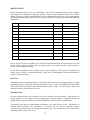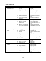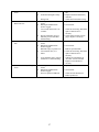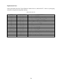
1
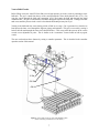
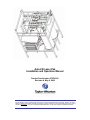
Auto-Fill Laser Pak
Installation and Operation Manual
Product Part Number AF55-0C00
Revision A, May 8, 2006
Do not attempt to use or maintain these units until you read and understand these instructions. Refer to the TaylorWharton’s Safety First booklet (TW-202) for handling cryogenic material. Do not permit untrained persons to use or
maintain this equipment. If you do not understand these instructions, contact your supplier for additional information.
______ Table of Contents
WARNING
Safety Precautions for Liquid Nitrogen
INTRODUCTION
System Description
Operation Sequence: Brief Overview
PIPING CIRCUITS
Vent to Bulk Circuits
Fill and Vent to Atmosphere Circuits
Pressure Building Circuits
Use Circuits
Safety Devices
Instrumentation Circuits
INSTALLATION
Handling
Pre-Installation Checks
Customer Installed Equipment/Piping
Electrical
Power
Error Alarm
Bulk Tank Pressure Line
OPERATION
Controller Operation
Graphic Terminal Operation
First Fill
Normal Operation
Long Duration Shutdowns
Restart
Error Conditions
Taking the Auto-Fill Laser Pak Out of Service
MAINTENANCE
Leak Test
Solenoid Valves
Safety Device Replacement
Instruments
Controller
Checking Vacuum
Trouble-Remedy Guide
Replacement Parts
APPENDIXES
Auto-Fill Laser Pak General Arrangement
Contoller, Auto-Fill Laser Pak
3
3
4
4
4
6
7
8
9
10
11
12
13
13
13
14
15
15
15
16
17
17
17
19
20
20
21
21
22
23
23
23
24
24
24
25
26
28
29
WARNING
The following safety precautions are for your protection. Before installing, operating, or maintaining this unit
read and follow all safety precautions in this section and in reference publications. Failure to observe all
safety precautions can result in property damage, personal injury, or possibly death. It is the responsibility of
the purchaser of this equipment to adequately warn the user of the precautions and safe practices for the use of
this equipment and the cryogenic fluid stored in it.
Safety Precautions for Liquid Nitrogen
Nitrogen is an inert, colorless, odorless, and tasteless gas making up four-fifths of the air you breathe. Liquid
nitrogen is obtained by cooling air until it becomes a liquid and then removing the oxygen. Air is roughly
one-fifth oxygen. Liquid nitrogen is at a temperature of -320°F (-196°C) under normal atmospheric pressure.
Extreme Cold - Cover Eyes and Exposed Skin
Accidental contact of liquid nitrogen or cold issuing gas with the skin or eyes may cause a freezing injury
similar to frostbite. Handle the liquid so that it won't splash or spill. Protect your eyes and cover the skin
where the possibility of contact with the liquid, cold pipes and cold equipment, or the cold gas exists. Safety
goggles or a face shield should be worn if liquid ejection or splashing can occur or cold gas can issue
forcefully from equipment. Insulated gloves that can be easily removed and long sleeves are recommended
for arm protection. Trousers without cuffs should be worn outside boots or over the shoes to shed spilled
liquid.
Keep Equipment Area Well Ventilated
Although nitrogen is non-toxic and non-flammable, it can cause asphyxiation in a confined area without
adequate ventilation. Any atmosphere not containing enough oxygen for breathing can cause dizziness,
unconsciousness, or even death. Nitrogen, a colorless, odorless, and tasteless gas, cannot be detected by the
human senses and will be inhaled normally as if it were air. Without adequate ventilation, the expanding
nitrogen will displace the normal air resulting in a non-life-supporting atmosphere.
Dispose of Waste Liquid Nitrogen Safely
Dispose of waste liquid nitrogen out-of-doors where its cold temperature cannot damage floors or driveways
and where it will evaporate rapidly. An outdoor pit filled with clean sand or gravel will evaporate liquid
nitrogen safely and quickly.
For more detailed information concerning safety precautions and safe practices to be observed when handling
cryogenic liquids consult CGA pamphlet P-12 "Handling Cryogenic Liquids" available from the Compressed
Gas Association, 1235 Jefferson Davis Highway, Arlington, VA 22202.
NOTE: Argon is an inert gas whose physical properties are very similar to those of nitrogen. For
handling of liquid argon, follow the safe practices described for the handling and use of liquid nitrogen.
CAUTION:
The Auto-Fill Laser Pak is not designed for use in oxygen service.
3
INTRODUCTION
This manual provides information for the operation and maintenance of Taylor-Wharton's Auto-Fill Laser Pak
cryogenic liquid pressurization system. The Auto-Fill Laser Pak is intended for use in applications requiring
nitrogen or argon at pressures higher than possible from standard 175 or 250 psig cryogenic bulk tanks.
Cryogenic liquid is supplied to the Auto-Fill Laser Pak from a standard bulk tank. The Auto-Fill Laser Pak
“boosts” the liquid up to pressures as high as 450 psig. Once the pressure of the cryogenic fluid is raised to the
desired level, the Auto-Fill Laser Pak is capable of delivering liquid to a downstream vaporizer at gas
equivalent rates as high as 15,000 standard cubic feet per hour. The supply of product out of the Auto-Fill
Laser Pak is continuous even when the bulk tank is being filled.
Product specifications, flow diagram, views, and important dimensions are shown on the general arrangement
drawing, AF55-0C00_GA, provided in this manual.
System Description
The Auto-Fill Laser Pak consists of three groups of components: vessels, piping circuits, and
control/instrumentation. These components are assembled to a stainless steel frame for easy installation.
Two 196-liter vessels are included in the system. Each vessel consists of a pressure vessel suspended inside a
jacket. The space between the pressure vessel and the jacket is evacuated and insulated with a microfiberglass / aluminum foil radiation shield. The pressure vessel is designed and constructed in accordance
with the ASME Boiler and Pressure Vessel Code Section VIII, Division 1. Both the inner pressure vessel and
vacuum jacket are constructed of type 304 stainless steel.
The piping circuits allow the vessels to vent, fill, pressurize, and deliver cryogenic liquid to the vaporizer.
Eight solenoid valves, four for each vessel, control flow. Two high capacity pressure builders, one for each
vessel, use heat from ambient air to maintain pressure in the vessels. Piping is type-304 stainless steel. Valves
are brass. Weld and compression type fittings are type-316 stainless steel. Compression fittings are double
ferrule type. Screwed fittings are machined from forged brass. The pressure builders are constructed of
aluminum.
The controller is housed inside a NEMA 4X fiberglass enclosure. Instrumentation consists of two differential
pressure transmitters and three pressure transmitters. A differential pressure transmitter is piped to each of the
vessels in order to measure liquid level. Gauge pressure transmitters monitor pressure in each of the vessels
and the bulk tank. The bulk tank pressure transmitter is provided with the system. All wiring is in accordance
with the National Electrical Code.
The Auto-Fill Laser Pak pressurizes cryogenic liquid by adding heat to the liquid in a controlled fashion. All
energy for building pressure is provided by heat from ambient air. Electrical power is required only to operate
the controller, instruments, and solenoid valves.
Operation Sequence: Brief Overview
Consider the following starting conditions: vessel A is empty of liquid and filled with high-pressure gas;
vessel B is filled with liquid and pressurized. (See piping schematic on page 6.)
1.
Liquid from vessel B is supplied at pressure to the vaporizer. Vessel B is in SUPPLY mode.
2.
High-pressure gas from vessel A is vented back to the bulk tank. Vessel A is in VENTING TO
BULK mode. This feature minimizes product loss during filling.
4
3.
Once the pressure in vessel A and the bulk tank are nearly equal, gas from vessel A is vented to the
atmosphere. Driven by the higher pressure in the bulk tank, liquid from the bulk tank flows into
vessel A. Vessel A is in FILLING mode.
4.
When vessel A is full, venting to atmosphere stops. Pressure in vessel A is increased by boiling
liquid in the pressure builder and returning it to the top of the vessel as gas. Vessel A is in
PRESSURIZING mode.
5.
Once pressure in vessel A reaches set point, flow through the pressure builder stops. Vessel A is in
STAND-BY mode.
6.
During the filling and pressurization process of vessel A, vessel B has been supplying an
uninterrupted flow of high-pressure liquid to the vaporizer. Pressure in vessel B is increased as
necessary by the pressure builder.
7.
When vessel B becomes empty of liquid, the system places vessel A in SUPPLY mode. Vessel B
begins the venting to bulk, filling, and pressurizing steps.
A more detailed explanation of the system operation is described in the next section, “Piping Circuits.”
5
PIPING CIRCUITS
The following paragraphs describe the operation of the piping circuits of the system. The descriptions refer to
the main components of each circuit and are grouped by function. Reference the piping schematic below and
in the general arrangement drawing for the component designations. Round stainless steel tags attached to the
system identify the components. Component tags ending with “A” identify components associated to vessel
A; tags ending with “B” identify components associated to vessel B. These component and circuit
descriptions should be understood before attempting operation.
AF55-0C00 has a
strainer following the
bulk connection
CN-1
PI-A
PI-B
PT-1B
PT-1A
PT-2A
PT-2B
RV-1A
V-7A
RV-1B
BD-A
V-6A
V-7B
CV-3A
V-5A
V-4A
BD-B
V-6B
CV-3B
V-5B
CV-1B
V-1A CV-1A
V-1B
V-2A CV-2A
V-2B CV-2B
V-3A
V-3B
PB-A
V-4B
Vessel “A”
CN-2
PB-B
Vessel “B”
Legend
CN-1
CN-2
CV-1
CV-2
CV-3
BD
PI
PT-1
PT-2
PT-3
Bulk Tank Connection
Vaporizer Connection
Liquid Use Check Valve
Vent to Bulk Tank Check Valve
Fill Check Valve
Rupture Disc
Vessel Pressure Gauge
Liquid Level Transmitter
Vessel Pressure Transmitter
Bulk Tank Pressure Transmitter
PB
V-1
V-2
V-3
V-4
V-5
V-6
V-7
RV-1
Pressure Builder
Liquid Use Solenoid Valve
Vent to Bulk Tank Solenoid Valve
Vent Solenoid Valve
Pressure Building Solenoid Valve
Liquid Phase Isolation Valve
Vapor Phase Isolation Valve
Equalization Valve
ASME Relief Valve
Figure 1: System Piping Schematic
6
Vent to Bulk Circuits
Before filling occurs, the Auto-Fill Laser Pak recovers high-pressure gas in the vessels by returning it to the
bulk tank. The gas is vented from the top of the vessel through the vent to bulk solenoid valve (V-2). Gas
exits the system through the bulk tank connection (CN-1) and enters the bulk tank through the liquid
withdrawal line. The gas is recondensed as it bubbles through the liquid in the bulk tank. Venting to the bulk
tank occurs until the pressure in the vessels is less than the bulk tank pressure plus 25 psi.
Venting to the bulk tank also occurs during periods of little or no usage. Gas is generated over time due to
heat input to the inner vessel through the supports, piping, and insulation. This gas is recovered by venting it
back to the bulk tank through the same circuit described above. This occurs when the pressure in the vessels
exceeds a user adjustable set point. This is similar to the “economizer” feature found on bulk cryogenic
vessels.
The user can deactivate these features by setting a controller parameter. This is described in the controller
operation section of this manual.
V-2A
CV-2A
CN-1
Figure 2: Vent to bulk circuit for vessel A highlighted in blue.
(Frame and wiring omitted from view for clarity.)
7
Fill and Vent to Atmosphere Circuits
Filling a vessel with liquid from the bulk tank occurs by pressure transfer. The pressure in a vessel is reduced
by venting gas from the top of the vessel to the atmosphere through the vent solenoid valve (V-3). A muffler
connected to the vent valve outlet keeps noise to a comfortable level. Liquid flows from the bulk tank,
through the liquid withdrawal line, and into the system through the bulk tank connection (CN-1). Liquid
flows through the fill check valve (CV-3) and into the vessel.
Note that filling occurs anytime the pressure in a vessel is less than that of the bulk tank.
V-3A
Muffler
CV-3A
CN-1
Figure 3: Fill and vent to atmosphere circuit for vessel A highlighted in blue.
(Frame and wiring omitted from view for clarity.)
8
Pressure Building Circuits
A pressure building circuit serves to build pressure after filling a vessel. The circuit is also used to ensure
sufficient driving pressure during product withdrawal periods. The controller opens the pressure building
solenoid valve (V-4) that creates a path from the liquid in the bottom of the container to the gas space in the
top. This path contains a pressure-building coil (PB) to vaporize product as it flows from the bottom to the top
of the vessel. Liquid is expanded to a vapor and pressure is increased in the vessel.
V-4B
PB-B
Figure 4: Pressure building circuit for vessel B highlighted in blue.
(Frame and wiring omitted from view for clarity.)
9
Use Circuits
The use circuit delivers pressurized liquid to an external vaporizer for use in the final application. The liquid
use solenoid valve (V-1) is opened. Liquid flows out of the vessel, through the liquid use solenoid valve and
liquid use check valve (CV-1), and exits the system through the vaporizer connection (CN-2).
V-1A
CN-2
CV-1A
Figure 5: Use circuit for vessel A highlighted in blue.
(Frame and wiring omitted from view for clarity.)
10
Safety Devices
The system has independent inner container relief devices piped to each of the vessels. Each set consists of a
primary relief valve (RV-1) to relieve pressure when it exceeds 600 psig. The valve reseats when pressure
drops below this point. In addition, each primary relief valve is supported by a secondary relief device
consisting of a rupture disc (BD). The rupture disc will burst at a pressure of approximately 875 psig. The
rupture discs require replacement in the event a safety valve malfunctions and allows vessel pressure to reach
the burst pressure rating.
RV-1B
BD-B
Figure 6: Safety circuit for vessel B highlighted in blue.
(Frame and wiring omitted from view for clarity.)
11
Instrumentation Circuits
The system instrumentation consists of liquid level transmitter, pressure transmitter, pressure gauges, and
isolation valves. The vessel pressure gauges (PI) display the inner container pressure in pounds-per-squareinch and kilopascals. A pressure gauge is piped to each of the vessels.
The liquid level transmitters (PT-1) measure the liquid level in the vessels. This instrument is a differential
pressure transmitter. Liquid inside the vessel creates slightly greater pressure at the bottom of the vessel than
at the top. The pressure differential increases with increasing liquid content. By measuring this differential
pressure, the liquid level is determined. One of these instruments is supplied for each of the vessels.
Three pressure transmitters monitor pressure in each of the vessels (PT-2) and the bulk tank (PT-3). The bulk
tank pressure transmitter is located inside the Auto-Fill Laser Pak control panel. The controller uses these
inputs to control supply pressure and venting to the bulk tank.
Isolation valves allow the instruments to be replaced without emptying and depressurizing the system.
The vapor phase isolation valve (V-6) isolates the liquid level transmitters, pressure gauges, and pressure
transmitters from the line (low pressure) connected to top of the inner vessel. The liquid phase isolation
valve (V-5) isolates the same instruments from the line (high pressure) connected to the bottom of the
inner vessel. The equalization valve (V-7) is used to equalize the pressure between the high and lowpressure sides of the liquid level transmitter.
V-5B
V-6B
PT-2B
PI-B
PT-1B
V-7B
Figure 7: Instrumentation circuit for vessel B highlighted in blue.
(Frame and wiring omitted from view for clarity.)
12
INSTALLATION
Dimension and connection data for the Auto-Fill Laser Pak can be found on the General Arrangement
Drawing in the appendix of this manual. System installation is the responsibility of the customer.
Handling
Employ experienced personnel to move and install the system. Ensure that rigging equipment, if used, has
adequate rated capacity to handle the system weight listed in the specifications. This system must be
shipped and lifted empty.
Important: The system may be handled by forklift from the side with the cylinders only. Lifting by forklift
from other sides may cause the system to be unstable and tip. When lifting by crane, use all four lift-eyes.
Lift-Eye
Forklift on
this side only
Figure 8: Handling
Pre-Installation Checks
Before installing the system, inspect it carefully for possible shipping damage. Report any damage to the
carrier and the factory. In addition, check system pressure as follows:
The system is shipped pressurized with nitrogen gas at 20 psig (1.38 bar/138 kPa). Record the "as received"
pressure for both vessels.
System pressure may change due to temperature variations, accidental opening of valves, or packing leaks. If
a positive pressure is not indicated on the vessel pressure gauges (PI) and no repairable leaks are found,
contact the factory. This pressure reading is essential to complete a “first fill” warranty claim.
13
Customer Installed Equipment/Piping
Designing safe and effective cryogenic systems requires extensive knowledge and experience. Persons
lacking the necessary skills are urged to seek competent advice before attempting to design cryogenic systems.
Design and consultation services are available from the factory. Contact information is provided at end of the
manual.
Important: When installing the vaporizer and piping be sure to follow accepted design practices for cryogenic
equipment. Use only components compatible with cryogenic liquids. Be sure to include pressure relief valves
in all piping where liquid product could be trapped between closed valves, regulators, etc. Any components
installed downstream of the bulk tank, including the bulk liquid withdrawal valve, must be rated for 500 psig
service pressure or higher.
Install the cryogenic bulk tank per the manufacturer’s instructions. It is recommended that a bulk tank with a
gross capacity of at least 500 gallons be used. Maximum operating pressure of the bulk tank should be 175 or
250 psig. Set the bulk tank pressure-building regulator to at least 100 psig.
If the bulk tank liquid withdrawal valve is not rated for service to 500 psig, it should be replaced. If this is not
possible, install a valve with an adequate pressure rating immediately downstream. Disable the upstream
valve by opening it and removing the valve handle. Wire tie a permanent tag to the valve reading, “DO NOT
CLOSE.”
It is recommended that a strainer, the same size as the bulk liquid withdrawal line, be installed downstream of
the bulk liquid withdrawal shut-off valve. The strainer will prevent particulate contamination from entering
the system and interfering with the function of the solenoid and relief valves. A strainer of mesh size 20 or
finer is recommended.
Install the Auto-Fill Laser Pak outdoors as close as possible to the bulk tank. This will minimize filling times
and allow maximum flow performance. If it is not possible to install the Auto-Fill Laser Pak reasonably close
to the bulk tank, the customer should consider the use of insulated piping. The line connecting the bulk tank
to the Auto-Fill Laser Pak should be pipe size ¾” or larger. Use a reducer immediately before the Auto-Fill
Laser Pak bulk connection (CN-1) to adapt to the ½” FNPT connection fitting.
The Auto-Fill Laser Pak vents gas while filling. In an area where this may cause risk of asphyxiation, the vent
valve outlets should be piped away to a safe location. Piping size and length should be designed to prevent
excessive pressure drop. Excessive pressure drop will cause extended filling times. When in doubt, monitor
the area with an oxygen level detector.
The vaporizer must have a maximum operating pressure of at least 500 psig. An operating pressure of 600
psig or greater is recommended. This allows the vaporizer relief valve to have a greater opening pressure than
the Auto-Fill Laser Pak relief valves. This reduces the possibility of product loss due to the vaporizer relief
valve opening prematurely. A vaporizer with adequate capacity must be specified. It is recommended that a
vaporizer rated for 15,000 SCFH be selected. The piping connection on the Auto-Fill Laser Pak for the
vaporizer (CN-2) is ½” female tapered pipe thread. Adapt the piping size to the vaporizer inlet as necessary.
Important: Ensure that the vaporizer is equipped with a relief valve with adequate flow capacity and proper
opening pressure. Follow the vaporizer manufacturer’s recommendations on selecting and installing the
proper relief valve.
14
Vaporizer
Bulk Liquid
Withdrawal Valve
Bulk Tank
CN-1
Auto-Fill
Laser Pak
CN-2
Control
Panel
Strainer
Vaporizer
Relief Valve
Bulk Tank
Pressure Line
Relief
Valve
Final Line
Regulator
To
Application
Vaporizer ShutOff Valve
System
Drain Valve
To
Atmosphere
Figure 9: Piping schematic for typical installation
Electrical
Only persons experienced with industrial wiring should perform the electrical installation. The installation
should conform to the National Electrical Code and any applicable local requirements. The control panel,
instruments, and solenoid valves are preinstalled and wired. Power and alarm (if used) are to be installed and
wired by the customer.
Two 1/2” female conduit hubs are provided pre-installed in the bottom of the control panel. See sheet 2 of the
general arrangement drawing in the appendix. The hub on the left (when facing the panel door) is intended for
power wiring. The hub on the right is for the alarm.
Power
Power electrical requirements are 20 amps, 120 volts alternating current at 60 Hz. It is recommended that the
power wiring be enclosed in rigid metal conduit.
Important: Before wiring power, turn the power switch on the front of the panel, to the “Off” position. Push
the “Start/Stop” button to the inward position.
A 20-amp breaker is provided inside the control panel in the lower left corner. This is the hot power
connection. The neutral power wire may be attached to any of the neutral power terminals. They are located
immediately to the right of the 20-amp breaker and are labeled “N”. A ground lug is mounted on the
enclosure sub-panel. The ground power wire should be attached to the lug.
Error Alarm
The customer may install an error alarm. This is not required for operation. Note that an error indicator light
is pre-installed on the front of the control panel. The customer provides the alarm horn, buzzer, or light. The
alarm must be powered by 120 volts alternating current. Connect the hot power wire of the alarm to the
terminal labeled R1-1. Connect the neutral power wire to any of the neutral power terminals labeled “N”.
The ground wire, if required, should be attached to the ground lug mounted on the enclosure sub-panel. The
Auto-Fill Laser Pak controller will activate the alarm when an error has been detected. A selector switch on
15
the front of the control panel disables the alarm. The panel error indictor light will continue to function if the
alarm is disabled. A table of alarm conditions is provided in the operation section of the manual.
Bulk Tank Pressure Line
Installation of a bulk tank pressure line is required for the Auto-Fill Laser Pak to operate. The bulk tank
pressure line should be connected to the bulk tank vapor (low pressure) instrument line. This line is also
commonly used for the bulk tank pressure gauge. Follow the bulk tank manufacturer’s instructions for
removing the pressure gauge. A convenient piping installation is to thread a 1/4" pipe nipple into the open
port. Thread a female tee fitting on to the nipple. Thread a stainless steel compression fitting for 3/8” OD
tube into the branch of the tee. Thread the pressure gauge into the tee. Connect a 3/8” OD stainless steel tube
to the compression fitting. Stainless steel is recommended over copper to reduce the possibility of damage to
the tube. Run the tube to the bulkhead compression fitting located on the bottom of the Auto-Fill Laser Pak
control panel. Teflon tape should be used on all piping connections except tube compression connections.
Use leak check fluid on all connections. Be sure to open the bulk tank instrument isolation valves and close
the equalization valve after the installation is complete.
16
OPERATION
These instructions are for operators experienced with cryogenic equipment. Before operating the Auto-Fill
Laser Pak, become familiar with the safety precautions in this manual and in the referenced publications.
Make certain all applicable provisions set forth in the Installation Section have been followed before placing
an Auto-Fill Laser Pak into operation. Study this manual and the general arrangement drawing located in the
back of this manual thoroughly. Know the location and function of all system components.
Controller Operation
The controller, located in the larger fiberglass enclosure, automates the operation of the Auto-Fill Laser Pak.
The controller inputs include: two liquid level transmitters (PT-1A & PT-1B), three pressure transmitters (PT2A, PT-2B, and the transmitter for the bulk tank), and the “Start/Stop” push button. Controller outputs
include the eight solenoid valves and the four lights on the front of the enclosure. A graphic terminal user
interface, located inside the enclosure, allows the operator to monitor the system and change settings. A
diagram showing the front of the enclosure, indicator lights, and switches is shown on page 2 of the drawing
titled “Controller, Auto-Fill Laser Pak” in the appendix.
The “Power” selector switch controls all power to the system. It should be in the “Off” position during system
installation and maintenance. If power is turned off or lost, all controller settings will be retained in the
memory. When power is reapplied the controller will automatically restart provided the “Start/Stop” button
remains in the inward position.
The “Start/Stop” button begins and stops the automatic operation sequence described in the Operation
Sequence Section. When the inward position is selected, power to the controller and transmitters remains
active and all the solenoid valves are deactivated. Solenoid valves are closed when deactivated unless
operated by manual override. This allows the operator to adjust the controller settings without running the
system. When the Start/Stop button is pulled outward, the controller begins the operation sequence.
The “Alarm” selector switch controls the user-installed alarm. In the “Off” position the alarm will not
function. In the “On” position the alarm will activate when the controller determines that an error has
occurred.
The “System Running” light indicates that the system is at the correct pressure and operating normally. The
“System Start” light becomes illuminated after pressing the “Start/Stop” button. It remains lit while the
system is filling or pressurizing at the beginning of the operation sequence. The “System Stop” light indicates
that the “Start/Stop” button has been pushed inward. It also becomes lit when the controller has stopped the
operation sequence due to an error condition.
The “Error” light indicates that the controller has detected an error condition. The controller activates the
user-installed alarm and the “Error” light simultaneously. Read the Error Conditions section for an
explanation of controller detectable errors.
Graphic Terminal Operation
System operation can be monitored or adjusted using the graphic terminal. It is located inside the panel in the
upper-right corner. Function keys, labeled F1 through F8, allow the operator to select the various screens.
Scroll through the settings displayed on the screen by pressing the left or right arrow keys. Change a setting
by scrolling to it and pressing the Enter key. Type the new value using the keypad. Pressing the Backspace
key deletes the last character entered. If all characters are deleted, pressing the Backspace key returns to the
previous screen without changing the value. Pressing the Enter key sets the value and returns to the previous
screen.
17
Display
F1
F2
F3
F4
F5
F6
F7
F8
Scroll
1
2
3
4
5
6
7
8
9
.
0
-
Enter
Backspace
Figure 10: Graphic Terminal
TAYLOR-WHARTON
A
B
Bulk
Pressure, PSIG
425
410
155
Percent Full
80
50
Vessel
Mode View
F1
Alarm
History
F2
Setting
Adj
F3
Figure 11: Default display screen
Six settings are user adjustable through the Graphic Terminal. The initial settings should be used in most
cases. However, the settings may be adjusted to better suit a particular installation. The Auto-Fill Laser Pak
should not be operated at pressures exceeding 500 psig. It is possible to cause the system to malfunction by
improperly setting these values. However, the system is designed to be inherently safe regardless of the
controller output. An explanation of each of the settings follows:
Pressure Builder Open – The pressure building solenoid valve (V4) will open when the pressure is less than
this setting. The valve will not open if the vessel is in Venting to Bulk or Filling mode. It is not
recommended to set this value above 450 psig.
Pressure Builder Range – If open, the pressure building solenoid valve (V4) will close when the pressure
exceeds this value plus the Pressure Builder Open setting.
Vent to Bulk – When a vessel pressure exceeds this value, the vent to bulk solenoid valve (V2) will open.
This is true for vessels in Stand-By mode or Supply mode. This feature allows gas that would otherwise be
lost through the relief valves to be recovered.
Bulk Pressure High – If the bulk tank pressure exceeds this value the system will not vent back to the bulk
tank.
18
Low Pressure Alarm – If the pressure of the vessel in Supply mode drops below this value the error alarm
and error indicator light will be activated.
System Vent to Bulk – The system will not vent back to the bulk tank if this parameter is turned off.
Setting
Pressure Builder Open
Pressure Builder Range
Vent to Bulk
Bulk Pressure High
Low Pressure Alarm
System Vent to Bulk
Initial Setting
450
30
510
230
370
On
Unit
psig
psi
psig
psig
psig
On/Off
Figure 12: Initial Settings
First Fill
The first fill should be performed manually. This is necessary to properly purge and control cooling of the
inner vessels. Calibration of the level transmitters is also covered in this procedure. It is recommended that
this procedure be performed once a year to recalibrate the level transmitters.
CAUTION: Follow the safety precautions at the beginning of this manual. Accidental contact with liquid or
cold gas can occur when operating the solenoid valve manual overrides.
1.
Press the start/stop button on the control panel inward. Turn the power switch to the “On” position.
Open the control panel door. With power on and the start/stop button pressed inward settings may be
adjusted on the graphic interface (Panel View) without running the system.
CAUTION:
Do not touch the wiring inside the control panel while power is activated. The
operator should touch only the graphic interface located in the upper right corner.
2.
Make sure that the manual override handles of all eight of solenoid valves are in the closed position.
The override is closed when the handle is turned counterclockwise fully. When closing the override,
the handle will move downward, away from the valve body.
3.
Slowly open the bulk liquid withdrawal valve. Open the valve completely.
4.
Turn the manual override handles of the vent solenoid valves (V-3A & V-3B) until venting begins.
Turn the handles two additional turns. The vessels are now being filled. First fill should be
performed slowly. The rate of filling can be adjusted by throttling the vent solenoid valves.
5.
While the vessels are filling, go to the control panel. On the graphic interface, from the default
screen, press “F3” to enter the setting adjustment screen. Press “F1” to enter the level scale screen.
The row labeled “Vessel Level” indicates the liquid level, in inches of water, for each of the vessels.
The vessel level reading will update continuously.
19
Level Scale
Vessel
Vessel Level
Scaled Min.
Scaled Max.
A
5
0
30
B
8
0
30
Exit F1
Figure 13: Level Scale Screen
6.
Each of the vessels should be filled until liquid exits the muffler. When this occurs, note the level
displayed on the screen and the vessel letter, A or B. Close the manual override of the vent
solenoid valve (V3) for the full vessel. Repeat this step for the other vessel.
7.
After the vent valves are closed, the vessel liquid levels will increase slightly until the vessel
pressure equalizes with the bulk tank. This is normal. Set the Scaled Max parameter for each of
the vessels to the readings noted in step 6. For nitrogen service the Scaled Max parameter is
typically 28; for argon service 39 is typical.
8.
Press the “F1” button to exit to the default screen. The controller now recognizes when the
vessels are liquid full. The level readings on the default screen are indicated by percent full;
100% meaning that the liquid level has reached the vent tube extending into the inner vessel. The
vessels are designed to allow a gas space above the liquid, even when the controller indicates
100% full.
9.
Press “F3” to enter the setting adjustment screen. The settings are set at the factory as indicated
in the Graphic Terminal Section of this manual. Verify that these parameters have been set to the
proper values. The user may change these settings to better suit a particular application.
10.
The system is now ready for operation. Pull the “Start/Stop” button outward to activate the
system.
Normal Operation
Once the Auto-Fill Laser Pak is started, it will run automatically. The user only needs to ensure that the bulk
tank does not run empty. The controller maintains liquid level in the vessels between 30 and 80 percent full.
You may notice that the liquid level reading displayed on the graphic terminal reads slightly erratic when the
relief valves open momentarily. This is normal and will not interfere with proper operation.
For shutdowns of a short duration, over-night and weekends, leave the power switch in the “On” position.
The “Start/Stop” button should remain in the outward position. Stop gas flow from the system by shutting off
valves at the application or by closing the vaporizer shut-off valve (see figure 9). The controller will
automatically minimize product loses by venting gas back to the bulk tank as necessary.
Long Duration Shutdowns
For shutdowns of a longer duration, exceeding three days, it is recommended that the Auto-Fill Laser Pak be
deactivated.
1.
Push the “Start/Stop” button inward.
2.
Turn the power switch to the “Off” position.
20
3.
Close the bulk liquid withdrawal valve.
Restart
When restarting after a long duration shutdown or if the bulk tank should run empty, the following procedure
is recommended.
CAUTION: Follow the safety precautions at the beginning of this manual. Accidental contact with liquid or
cold gas can occur when operating the solenoid valve manual overrides.
1.
Press the start/stop button on the control panel inward. Turn the power switch to the “On” position.
Open the control panel door. With power on and the start/stop button pressed inward settings may be
adjusted on the graphic interface (Panel View) without running the system.
CAUTION:
Do not touch the wiring inside the control panel while power is activated. The operator
should touch only the graphic interface located in the upper right corner.
2.
Make sure that the manual override handles of all eight of solenoid valves are in the closed position.
The override is closed when the handle is turned counterclockwise fully. When closing the override,
the handle will move downward, away from the valve body.
3.
If the bulk liquid withdrawal valve is closed, slowly open it. Open the valve completely.
4.
Turn the manual override handles of the vent solenoid valves (V-3A & V-3B) until venting begins.
Turn the handles two additional turns. The vessels are now being filled. Filling should be performed
slowly. The rate of filling can be adjusted by throttling the vent solenoid valves.
5.
While the vessels are filling, go to the control panel. On the graphic interface, go to the default
setting screen. The first line of the default screen reads “TAYLOR-WHARTON”. Monitor the
liquid level of the vessels in this screen.
6.
Each of the vessels should be filled to approximately 70 percent full. When this liquid level is
reached for one of the vessels, close the manual override of the vent solenoid valve (V3) for the
vessel. Repeat this step when the other vessel reaches approximately 70 percent full.
7.
After the vent valves are closed, the vessel liquid levels will increase slightly until the vessel
pressure equalizes with the bulk tank. This is normal.
8.
The system is now ready for operation. Pull the “Start/Stop” button outward to activate the
system.
Error Conditions
In the event of an error, the controller will activate the error alarm and error panel light. The Auto-Fill Laser
Pak will continue to supply product until the vessel in “Supply” mode becomes empty. Some errors will
cause the controller to immediately stop operation. The reason for the error will be indicated on the graphic
terminal by a text message. The error will also be recorded in the Error Log along with the date and time.
View the error log by pressing F3 from the default screen. A list of controller detectable errors follows:
21
Message
Meaning
Vessel “X” Pressure Low
Transmitter “X” Error
Vent to Bulk Time Out
Fill Time Out
Vessel pressure dropped below alarm setting.
No signal from transmitter.
Vent to Bulk time exceeded 10 minutes.
Fill time exceeded 10 minutes.
Supply vessel emptied before filling cycle
completed for other vessel.
Pressurization time exceeded 10 minutes.
Filling Error
Pressurization Time Out
Immediate System
Stop
No
Yes
No
No
No
No
Figure 14: Error Messages
Once the error has been resolved, the controller must be restarted. Restart the controller by pressing the
“Start/Stop” button inward and pulling it back outward. If the Auto-Fill Laser Pak has been emptied for
maintenance or remained in error mode for an extended period of time it will be necessary to follow the
“Restart” procedure above.
Taking the Auto-Fill Laser Pak Out of Service
In order to empty and depressurize the Auto-Fill Laser Pak, perform the following steps:
1.
Deactivate the system by pressing the “Start/Stop” button inward. Turn the alarm switch to the
“Off” position.
2.
Close the bulk tank liquid withdrawal valve.
3.
Close the vaporizer shut-off valve and open the system drain valve. (These valves are shown in
figure 9.) The system drain valve may be throttled as necessary to control noise.
4.
Open the liquid use solenoid valves (V-1A and V-1B).
5.
Monitor the liquid level in the vessels on the graphic interface. The vessels are empty when the
liquid level and pressure are zero. Note that the system may be empty and indicate a small
positive or negative value. This is normal transmitter error.
6.
Close the liquid use solenoid valves (V-1A and V-1B). Make sure that the manual overrides on
all solenoid valves are in the closed position.
7.
Crack open the bulk tank liquid withdrawal valve for a second to slightly pressurize the Auto-Fill
Laser Pak. Bleed the pressure down on both vessels to approximately 20 psi using the vent
solenoid valve (V3) manual override handles.
8.
Turn the power switch to the “Off” position.
22
MAINTENANCE
Routine inspections of the system are recommended. The need for maintenance usually becomes apparent
from inspection and indications of improper operation. Typical trouble indications would be error alarms,
leakage from valves or piping connections, and excessive venting through relief valves. Keep a permanent log
of all inspections and repairs performed. Such a log can be valuable in evaluating performance and scheduling
maintenance.
Date
Nature of Work (Describe in Full)
Remarks
Servicemen's Signature
Figure 15: Inspection and Repair Log (Sample Form)
Always observe the safety precautions at the front of this manual and follow the instructions given in this
section. Before working on piping, isolate the piping section to be repaired from the vessels, and relieve
pressure on the component or piping.
Do not allow unqualified persons to attempt repairs on this equipment. Field repairs to instruments and
controls must be made by a qualified electrician. Refer to the Trouble-Remedy Guide in this manual for
assistance in troubleshooting.
Leak Test
After making repairs requiring disassembly or replacement, leak test all valves or piping joints that were taken
apart and reconnected. Apply leak detector fluid to the test surface. Large leaks instantly form large bubble
clusters, while fine leaks produce white foam that builds up more slowly. All leaks must be repaired and
retested before the system is returned to service.
Solenoid Valves
The most common trouble with a solenoid valve will be leakage at the stem packing. Packing leaks are
usually indicated by ice emerging from the packing gland or retainer threads. If tightening cannot stop
packing leakage, replace the packing. Use preformed packing ordered from the valve manufacturer.
The solenoid valves may be rebuilt without removing the valve body from the system. Rebuild kits are
available from the solenoid valve manufacturer. If necessary the valve may be completely replaced.
Compression type fittings make valve replacement relatively easy. It is not necessary to cut, weld, or braze
the piping in order to remove the valves.
23
Order replacement parts from the valve manufacturer. Be sure to give all information on the valve nameplate,
including the factory part number, to ensure receiving the correct parts for these valves.
Atkomatic – Circle Seal Controls Inc.
P.O. Box 3300
Corona, California 92878 U.S.A.
Phone: 951-270-6200
Fax:
951-270-6201
Web: www.circle-seal.com/atkomatic/
Safety Device Replacement
In order to replace the safety devices the system pressure must reduced to zero gauge pressure. It is not
necessary to empty the system of liquid. Push the start/stop button on the control panel and turn the power
switch off. Close the liquid auxiliary valve on the bulk tank. Manually open both of the vent valves (V3-A &
V3-B). Be sure that the vapor phase isolation valves (V6-A & V6-B) are open. Once the vessel pressure
gauges (PI-A & PI-B) indicate zero and flow through the vent valves has stopped, the safety devices may be
replaced.
If a rupture disc (BD) bursts, determine and correct the cause of the rupture before replacing the device. These
devices should be replaced annually as a preventive maintenance procedure. The rupture discs on this tank are
sealed assemblies that must be replaced as a unit.
Vessel relief valves (RV) that leak or fail to operate at the set pressure should be replaced immediately. Do
not attempt to repair these components.
Instruments
The major cause of a malfunctioning level transmitter (PT-1) is an open equalization valve (V-7). Closed
liquid or vapor phase isolation valves (V-5 & V-6) are another likely cause of malfunction. Leakage in the
gauge lines may also cause the instrument to read incorrectly. Instructions for recalibrating the level
transmitters are included in the section titled “First Fill”. If the problem is not readily corrected, replace the
transmitter with a spare.
A malfunctioning vessel pressure gauge (PI) or vessel pressure transmitter (PT2) may be caused by a closed
liquid or vapor phase isolation valve (V-5 or V-6). If the problem is not readily corrected, replace the gauge
or pressure transmitter with a spare.
Controller
A qualified electrician should perform controller maintenance. Most controller components are readily
available Allen-Bradley parts. The controller wiring drawing, included in the appendix of this manual,
contains a detailed wiring schematic and bill of materials. The most likely problem on the controller is a
failed fuse. Should it be necessary, the programmable logic controller (PLC) may be sent to Taylor-Wharton
for reprogramming. Contact the Taylor-Wharton Customer Service Department at 1-800-898-2657.
24
Checking Vacuum
This product is carefully designed, manufactured, and tested with every effort made to eliminate vacuum
space leakage. An absorbent material (molecular sieve) and a reactive chemical (palladium oxide) are sealed
inside the vessel casing to help maintain the vacuum over a long period of time. However, some vacuum
deterioration may be experienced after years of service due to out-gassing of materials inside the vacuum
space. To determine if vacuum deterioration has occurred perform an evaporation rate test:
1.
Press the Start/Stop button on the control panel inward while leaving the power switch in the
“On” position.
2.
Close the liquid auxiliary valve on the bulk tank.
3.
Slowly open the vent valve (V3) of the vessel with the suspect vacuum using the manual
override. Use a face shield and insulated gloves to protect against possible contact with liquid.
Allow the vessel to vent down to atmospheric pressure. This may require an hour or more.
4.
Check the liquid level reading of the vessel on the display inside the control panel. If it is less
than 50 percent it will be necessary to add more liquid. Slowly open the liquid auxiliary valve on
the bulk tank. Fill the vessel to greater than 50 percent full and close the valve.
5.
Leave the vent valve (V3) open. After 24 hours, note the liquid level reading of the vessel. Take
a second reading after another 24-hour interval. Compare the two readings.
A liquid level decrease exceeding 15% over a 24-hour period may indicate a vacuum problem. Condensation
or even ice on the vessel jacket is another indication of a vacuum problem. Note that some icing or
condensation is normal around the piping connections of the vessel. Condensation may also occur on the
vessel’s outer surface as a result of high humidity.
If it has been determined that the vessel has a vacuum problem, it will be necessary to repair or replace the
vessel. A skilled service technician should perform vessel replacement or repair. Contact Taylor-Wharton
customer service at 1-800-898-2657 for assistance in locating the closest service center.
25
Trouble-Remedy Guide
Trouble
Possible Cause
Remedy
1.
a.
a. Thaw out valve or replace if
necessary.
b. Replace rupture disc.
c. Leak test and repair piping.
d. Check fuse and wiring. Clean,
seat, rebuild, or replace solenoid
valve if necessary.
e. Check for leaks downstream.
Reduce product use.
f. Turn on controller and pull start
button.
g. Thaw pressure building coils.
2.
3.
4.
5.
Pressure low, controller error text
“Vessel Pressure Low” or
“Pressurization Time Out”.
Excessive system pressure.
Erratic or erroneous liquid level
readings.
Leaking relief valve (RV).
Ruptured pressure vessel rupture
disc (BD).
b.
c.
d.
Safety valve (RV-1) leaking or
frozen open.
Rupture disc (BD) rupture.
Piping leaks to atmosphere.
Pressure building solenoid (V-4)
failure.
e.
Excessive product withdrawal.
f.
Controller off or not started.
g.
Excessive frost on pressure
building coils.
a.
b.
c.
Extensive shutdown time.
Low withdrawal rate.
Malfunction of pressure
building circuit.
d.
e.
Malfunction of pressure gauge
(PI) or pressure transmitter (PT2).
Bad vessel vacuum.
a.
b.
c.
Leaking gauge lines.
By-pass valve open.
Blown fuse.
d.
e.
f.
g.
Liquid level transmitter (PT-1)
damaged or faulty.
Gauge lines reversed.
Wiring fault.
Plugged gauge lines.
a.
Dirt or ice in valve.
b.
c.
a.
Improper valve set point.
Damaged valve seat.
Excessive vessel pressure.
b.
c.
d.
Defective rupture disc.
Atmosphere corrosion and/or
disc fatigue.
Interior disc corrosion.
e.
f.
Improper rupture disc.
Relief device failed.
26
a. No remedy.
b. No remedy.
c. Clean, rebuild, or replace
pressure building solenoid valve
(V-4).
d. Compare gauge to transmitter
reading. Replace defective unit.
e. Have vessel repaired and reevacuated.
a. Test and repair leaks.
b. Close by-pass valve.
c. Check for electrical short; replace
fuse.
d. Replace liquid level transmitter
(PT-1).
e. Connect properly.
f. Check and fix transmitter wiring.
g. Disconnect lines at liquid level
transmitter (PT-1) and test for
flow.
a. Thaw out valve. Replace if
necessary.
b. Replace valve.
c. Replace valve.
a. Refer to Step 2, this section.
Replace rupture disc.
b. Replace rupture disc.
c. Replace rupture disc.
d. Blow out safety device line.
Replace rupture disc.
e. Install correct rupture disc.
f. Replace relief device and rupture
disc.
6.
7.
Controller error text, “Transmitter
Error”.
Controller error text, “Vent to
Bulk Time Out”.
a.
Blown fuse.
d.
Transmitter damaged or faulty.
c.
a.
Wiring fault.
Bulk liquid withdrawal valve
closed.
Bulk liquid withdrawal line
strainer clogged.
Vent to bulk solenoid valve (V2) failure.
d.
c.
d.
8.
Controller error text, “Fill Time
Out”.
a.
d.
c.
d.
9.
Controller error text, “Filling
Error”.
Pressure transmitter (PT-2) or
bulk tank pressure transmitter
malfunctioning.
Bulk liquid withdrawal valve
closed.
Bulk liquid withdrawal line
strainer clogged.
Bulk tank empty or pressure low.
Vent solenoid valve (V-3)
failure.
e.
Level transmitter (PT-1) requires
calibration or is malfunctioning.
a.
Bulk liquid withdrawal valve
closed.
Bulk liquid withdrawal line
strainer clogged.
Excessive product withdrawal.
d.
c.
27
a. Check for electrical short; replace
fuse.
d. Replace transmitter indicated by
controller.
c. Check and fix transmitter wiring.
a. Open valve.
d. Clean strainer.
c. Check fuse and wiring. Rebuild or
replace solenoid valve if
necessary.
d. Check against accurate pressure
gauge. Replace if necessary.
a. Open valve.
d. Clean strainer.
c. Refill or repair bulk tank.
d. Check fuse and wiring. Rebuild or
replace solenoid valve if
necessary.
e. Calibrate level transmitter per
“First Fill” section of manual.
Replace level transmitter if
necessary.
a. Open valve.
d. Clean strainer.
c. Check for leaks downstream.
Reduce product use.
Replacement Parts
Order replacement parts from Taylor-Wharton Customer Service (1-800-898-2657). Refer to system piping
schematic on the general arrangement drawing.
Replacement Parts List
ITEM
CV-1, CV-2
CV-3
BD
PI
PT-1
PT-2
PT-3
PB
V-1, V-2, V-3
V-4
V-5, V-6, V-7
RV
PART NUMBER
85441390
85441395
85088188
7702-6197
57408750
57408626
57408627
AF55-9C28
85456547
85456552
85443725
2198235
AF55-9C02
AF55-6C00
AF55-9C12
DESCRIPTION
Valve, Check, 1/2" FNPT
Valve, Check, 1/2" FNPT, 5 psi Crack Pressure
Rupture Disc, ASME, 811 PSI, 1/2" MNPT
Pressure Gauge, 600 PSIG, 1/4” MNPT
Differential Pressure Transmitter, 100” H2O
Pressure Transmitter, 500 PSIG
Pressure Transmitter, 1000 PSIG
Pressure Builder
Valve, Solenoid, 1/2" FNPT
Valve, Solenoid, 3/4" FNPT
Valve, Globe, 1/4” MNPT
Safety Valve, ASME, 500 PSI, 1/2" Inlet X 3/4" Outlet
Complete Controller in Enclosure
Complete Vessel without Piping
Flow Schematic Decal
28
APPENDIXES
Appendix 1 - Auto-Fill Laser Pak General Arrangement
Appendix 2 - Controller, Auto-Fill Laser Pak
29
4075 Hamilton Blvd.
Theodore, Alabama 36582 U.S.A.
Telephone (251) 443-8680
Fax (251) 443-2250
In U.S. and Canada:
(800) TW TANKS (898-2657)
Manual P/N 99187847