1
Scanning Magnetic
Microscope
1000
Computer Controlled
3 Channel Magnetometer System
TRISTAN TECHNOLOGIES
SAN DIEGO, CALIFORNIA
copyright 1993
U.S.A.
Revision Record
Date
August, 1993
Oct 5, 1993
Revision
XA
A
Description
Product Release
1993 by Tristan Technologies, Inc.
All rights reserved. No part of this manual may be reproduced, stored in a retrieval system, or
transmitted in any form or by any means, electronic, mechanical, photocopying, recording, or
otherwise, without prior written permission of Tristan Technologies, Inc.
Tristan reserves the right to change the functions, features, or specifications of its products at any
time, without notice.
Any questions or comments in regard to this product and other products from Tristan, please
contact:
Tristan Technologies, Inc.
6191 Cornerstone Court E, Ste 107
San Diego, CA 92121
U. S. A.
phone:
fax:
(619) 550 - 2700
(619) 550 - 2799
CRYOLAB is a trademark of CRYOLAB Corporation.
GraphiC 6.0 is a trademark of Scientific Endeavors Corporation.
LabWindows is a trademark of National Instruments Corporation.
microPREAMP and QUANTUM DESIGN are trademarks of QUANTUM DESIGN Inc.
W AVETEK is a trademark of Wavetek Corporation.
copyright 1992 - 1993 Tristan Technologies ii SMM 1000 System User's Manual
Table of Contents
Table of Contents ........................................................................................................................ iii
List of figures ............................................................................................................................... vi
WARRANTY ................................................................................................................................ vii
Chapter 1: Introduction ............................................................................................................... 1-1
1.1. SYSTEM OVERVIEW........................................................................................................... 1-1
1.1 CRYOGENIC SQUID CHIP ................................................................................................... 1-4
1.2. COMPUTER CONTROL AND DATA ACQUISITION ........................................................... 1-5
1.2.1. Computer Hardware ............................................................................................. 1-5
1.2.2. Custom Software .................................................................................................. 1-5
1.2.2.1. -- AC Field Control ................................................................................ 1-5
1.2.2.2. -- DC Field Control ................................................................................ 1-5
1.2.2.3. -- SQUID Control .................................................................................. 1-5
1.2.2.4. -- Heater Control ................................................................................... 1-6
1.2.2.5. -- Interface to Automated Motion Control ............................................. 1-6
1.2.2.6. -- AC Signal Nulling .............................................................................. 1-6
1.2.2.7. -- Automated Data Acquisition Procedures .......................................... 1-6
1.2.2.8. -- Data Analysis Functions .................................................................... 1-7
1.2.2.9. -- Data Plotting Functions ..................................................................... 1-7
3. MAGNETIC FIELD SYSTEM ................................................................................................... 1-8
1.3.1. DC Field ................................................................................................................ 1-8
1.4. Control Console .................................................................................................................... 1-10
1.7. MEASURED PARAMETERS AND FACTORY TEST DATA ............................................... 1-11
1.7.1. System details ...................................................................................................... 1-11
Chapter 2: SAFETY PRECAUTIONS .......................................................................................... 2-1
2.1. SAFETY PRECAUTIONS FOR HANDLING LIQUID HELIUM AND LIQUID
NITROGEN .................................................................................................................................. 2-1
2.2. Extreme Cold-- Cover Eyes and Exposed Skin .................................................................... 2-1
2.3. Keep Air and Other Gases Away from Liquid Helium ........................................................... 2-1
2.4. Keep Exterior Surfaces Clean to Prevent Combustion ......................................................... 2-1
2.5. Pressure-Relief Devices Must Be Adequately Sized ............................................................ 2-1
2.6. Keep Equipment Area Well Ventilated.................................................................................. 2-2
Chapter 3: INSTALLATION ......................................................................................................... 3-1
3.1 INITIAL INSPECTION ............................................................................................................ 3-1
3.2 REPACKING FOR RETURN SHIPMENT ............................................................................. 3-1
3.3 SYSTEM COMPONENTS ..................................................................................................... 3-2
Chapter 4: NORMAL OPERATION ............................................................................................. 4-1
4.1 REFILLING THE DEWAR WITH LIQUID HELIUM ............................................................... 4-1
4.2 Mounting Sample ................................................................................................................... 4-1
2. Verify x,y,z Motion and Sensors ................................................................................ 4-2
3. Leveling:..................................................................................................................... 4-2
* If unable to use Z sensor the sample may be leveled via the following
procedure:.......................................................................................................... 4-2
4. Vacuum Can Assembly: ............................................................................................ 4-2
5. Pump down / He purge .............................................................................................. 4-2
6. Cool Down ................................................................................................................. 4-3
7. Warm Up ................................................................................................................... 4-3
4.3 TUNING THE SQUID AND OPERATING THE CONTROL ELECTRONICS ........................ 4-3
Chapter 5: USER INTERFACE.................................................................................................... 4-1
5.1. BASIC DESCRIPTION ......................................................................................................... 4-1
5.2. MENU BARS AND HARDWARE CONFIGURATION .......................................................... 4-1
5.3. PULL-DOWN MENUS AND PANELS ................................................................................. 4-2
5.4. DESCRIPTION OF PULL-DOWN MENU TITLES .............................................................. 4-2
5.4.1. AC Field Setup PULL-DOWN MENU .................................................................. 4-3
5.4.2. DC Magnet Ramp PULL-DOWN MENU ............................................................. 4-3
copyright 1992 - 1993 Tristan Technologies iii SMM 1000 System User's Manual
5.4.3. SQUID Control PULL-DOWN MENU ................................................................... 4-4
5.4.4. System Parameter PULL-DOWN MENU ............................................................. 4-6
5.4.5. AC Field Null PULL-DOWN MENU ..................................................................... 4-7
5.4.6. Data Acquisition PULL-DOWN MENU ................................................................. 4-8
5.4.7 Enter Timing Parameters MENU ........................................................................... 4-10
5.4.8. Auto Position Acq PULL-DOWN MENU ............................................................... 4-11
5.4.9. Select Files Pop-up MENU ................................................................................... 4-12
5.4.10. Create Position File Pop-up MENU and PULL-DOWN MENU ........................... 4-12
5.4.11. Manipulate Data PULL-DOWN MENU ............................................................... 4-13
5.4.12. XY Plot PULL-DOWN MENU ............................................................................ 4-17
5.4.13. SQUID Control Status PULL-DOWN MENU ..................................................... 4-19
5.4.14. GPIB Help PULL-DOWN MENU ........................................................................ 4-20
5.4.15. Heater and Relay Control PULL-DOWN MENU ................................................. 4-21
5.4.16. Function Generator Control PULL-DOWN MENU ............................................. 4-22
5.4.17. Helium Level PULL-DOWN MENU.................................................................... 4-23
5.4.18. Check PC Memory PULL-DOWN MENU ........................................................... 4-23
5.4.19. Convert File to ASCII PULL-DOWN MENU........................................................ 4-23
5.4.20. Convert Header to ASCII PULL-DOWN MENU.................................................. 4-24
5.4.21. Convert ASCII to File PULL-DOWN MENU........................................................ 4-24
5.4.22. Dummy Output File PULL-DOWN MENU .......................................................... 4-24
5.4.23. Manual Scanner Control Pop-Up MENU ............................................................ 4-24
5.4.24. XY Plot Labels Pop-Up MENU ........................................................................... 4-25
5.4.25. XY Plot Manual Scaling Pop-Up MENU.............................................................. 4-26
5.4.26. XY Plot Enter Manual Scaling Pop-Up MENU .................................................... 4-26
5.4.27. High Speed Acquisition PULL-DOWN MENU .................................................... 4-27
5.4.28. Convert File to Spreadsheet PULL-DOWN MENU............................................. 4-28
5.5. 3d (3 Dimensional) GraphiC program ................................................................................... 4-30
5.5.1. 3d (3 Dimensional) PLOT PROGRAM ................................................................ 4-30
5.5.1.1. 3d Plotting Inputs MENU ................................................................................... 4-30
5.5.1.2 3d Plot Parameters MENU ................................................................................. 4-31
5.5.2 CONTOUR PLOT EXAMPLE ................................................................................ 4-34
5.5.3 SURFACE PLOT EXAMPLE ................................................................................. 4-35
5.5.4 3D HARD COPY OPTIONS................................................................................... 4-35
5.6. EXTERNAL "DOS" PROGRAMS ......................................................................................... 4-36
5.6.1. NDE System Batch File Menu Utility.................................................................... 4-36
5.7. TYPICAL AC ACQUISITION AND ANALYSIS MENU SELECTION ................................... 4-38
Chapter 6: FILE STRUCTURE & MAINTENANCE ..................................................................... 5-1
6.1 DIRECTORY STRUCTURE AND EXAMPLE DATA FILE .................................................... 5-1
6.1.1 (NDE) DIRECTORY STRUCTURE ....................................................................... 5-1
6.1.2 FILE STRUCTURE DESCRIPTION ...................................................................... 5-2
6.1.3 EXAMPLE "SYSTEM.TTI" FILE ........................................................................... 5-4
6.1.4 EXAMPLE "STARTUP.CFG" FILE ........................................................................ 5-7
6.1.5 EXAMPLE RAW DATA ACQUISITION FILE ........................................................ 5-9
6.1.7 NDE PRINTER CONFIGURATION ....................................................................... 5-14
6.1.8 3D PRINTER CONFIGURATION .......................................................................... 5-14
6.1.9 DATA ACQUISITION ERROR LOGGING ............................................................. 5-14
6.2 NDE Software Modifications .................................................................................................. 5-14
6.2.2 Accessing NDE Data Files..................................................................................... 5-15
Chapter 7: MAINTENANCE ......................................................................................................... 6-1
7.1 DEWAR VACUUM ................................................................................................................. 6-1
APPENDIX A: ADDITIONAL INFORMATION ............................................................................ A-1
A.1 SETUP .................................................................................................................................. A-1
A.2 COMPUTER HARDWARE SETUP....................................................................................... A-1
A.3. Probe Top Wiring ................................................................................................................. A-6
A.4 SMM Installation .................................................................................................................... A-11
copyright 1992 - 1993 Tristan Technologies iv SMM 1000 System User's Manual
List of figures
Figure 1-1: System block diagram ............................................................................................... 1-1
Figure 1-2: Cryogenic dewar & probe .......................................................................................... 1-2
Figure 1-3: Cryogenic dewar Dimension ..................................................................................... 1-3
Figure 1-4: Squid Chip ................................................................................................................ 1-4
Figure 1-5: Sample surface plot from a scan of a magnetic disk. ............................................... 1-8
Figure 1-6: Magnetic Field as a function of distance along the axis ............................................ 1-8
Figure 1-7: Superconducting magnetic field circuit ...................................................................... 1-9
Figure 1-8: Control Console ......................................................................................................... 1-10
Figure 3.5.1: Floor Layout ............................................................................................................ 3-3
Figure 5.1: Menu Bar with hardware installed.............................................................................. 4-1
Figure 5.2: Menu Bar without hardware installed......................................................................... 4-2
Figure 5.3: Pull-Down Menus....................................................................................................... 4-2
Figure 5.4.1: AC Field Setup Menus ............................................................................................ 4-3
Figure 5.4.2.1 DC Field Ramp Menus ......................................................................................... 4-3
Figure 5.4.2.2 DC Ramp File Illustration ...................................................................................... 4-4
Figure 5.4.3 SQUID Control Menus ............................................................................................. 4-6
Figure 5.4.4 System Parameter Menus ....................................................................................... 4-6
Figure 5.4.5 AC Field Nul Menus ................................................................................................. 4-7
Figure 5.4.6.1 Data Acquisition Only Scan Menus ...................................................................... 4-8
Figure 5.4.6.2 Remote mode timing illustration ........................................................................... 4-10
Figure 5.4.7 Enter Timed Mode Parameters Menus ................................................................... 4-11
Figure 5.4.8 Auto Position Scan Menus ...................................................................................... 4-11
Figure 5.4.9 Select Files Menus .................................................................................................. 4-12
Figure 5.4.10 Create Position File Pop-up Menus ....................................................................... 4-13
Figure 5.4.11 Manipulate Data Menus ......................................................................................... 4-14
Figure 5.4.12 XY Plota Menus ..................................................................................................... 4-19
Figure .5.4.13 Parameters Menus ............................................................................................... 4-20
Figure 5.4.14 GPIB Help Menus .................................................................................................. 4-21
Figure 5.4.15 Heater and Relay Control Menus .......................................................................... 4-22
Figure 5.4.16 Function Generator Control Menus ....................................................................... 4-23
Figure 5.4.17 Helium Level Menus .............................................................................................. 4-23
Figure 5.4.23 Manual Scanner Control Pop-Up Menu ................................................................. 4-25
Figure 5.4.24 XY Plot Labels Pop-Up Menu ................................................................................ 4-26
Figure 5.4.25 XY Plot Manual Scaling Pop-Up Menu ................................................................. 4-26
Figure 5.4.26 XY Plot Enter Manual Scaling Pop-Up Menu ....................................................... 4-27
Figure 5.4.27 High Speed Acquisition Pull-Down Menu .............................................................. 4-28
Figure 5.4.27 High Speed Acquisition Pull-Down Menu .............................................................. 4-29
Figure 5.5.1.1 3d Plotting Inputs Menus ..................................................................................... 4-31
Figure 5.5.1.2 3d Plot Parameters Menus ................................................................................... 4-33
Figure 5.5.2.Sample Contour Plot ............................................................................................... 4-34
Figure 5.5.3 Sample Surface Plot ................................................................................................ 4-35
Figure A-3.1: Probe Top Diagram............................................................................................... A-6
Figure A-3.2: Probe Wiring Diagram #1 ..................................................................................... A-7
Figure A-3.3: Probe Wiring Diagram #2 ..................................................................................... A-8
Figure A-3.4: Probe Wiring Diagram #3 ..................................................................................... A-9
Figure A-3.5: Probe Wiring Diagram #4 ..................................................................................... A-10
copyright 1992 - 1993 Tristan Technologies v SMM 1000 System User's Manual
WARRANTY
WARRANTY
Tristan Technologies warrants its products to be free from defects in material and workmanship.
Obligations under this warranty shall be limited to replacing, repairing, or giving credit for the
purchase price, at Tristan's option, of any instrument returned, shipment prepaid, to its factory for
that purpose within one year of delivery to the original purchaser, provided prior authorization for
such return has been given by an authorized Tristan representative.
This warranty shall not apply to any instrument which Tristan's inspection discloses to have
become defective or unworkable due to abuse, mishandling, misuse, accident, alteration,
negligence, improper installation, or other causes. This warranty shall not apply to any instrument
or component not manufactured by Tristan. When products manufactured by others are included
in Tristan's equipment, the original manufacturer's warranty, if any, is extended to purchaser to the
extent permitted by that manufacturer.
Tristan reserves the right to make changes in design at any time without incurring any obligation
to install same on units previously purchased.
There are no warranties which extend beyond the description herein.
This warranty is in lieu of, and excludes any and all other warranties or representations,
expressed, implied or statutory, including merchantability and fitness for purpose as well as any
and all other obligations or liabilities of seller, including, but not limited to, special or consequential
damages. No person, firm or corporation is authorized to assume for Tristan any additional
obligation or liability not expressly provided for herein.
copyright 1992 - 1993 Tristan Technologies vi SMM 1000 System User's Manual
Chapter 1: Introduction
1.1. SYSTEM OVERVIEW
The main components of the system are:
-- Liquid Helium Dewar
-- Three-Channel Scanning SQUID Magnetometer Probe
-- Computer Control and Data Acquisition System
-- Pump Down and Warm Up Station
-- Probe Crane
-- Probe Stand
-- Control Console
-- Miscellaneous Accessories
Optical Microscope /w stand
Lab Jack
Motor Cable
Position Sensor Cable
X-Y Stage Extension Cable
One GPIB cable (6')
Level Meter Cable 15'
These components are shown in Figures 1-1 & 1-3.
Figure 1-1: System block diagram
copyright 1992-1993 Tristan Technologies 1 - 1
SMM 1000 System User's Manual
Figure 1-2: System Front View
copyright 1992-1993 Tristan Technologies 1 - 2
SMM 1000 System User's Manual
Figure 1-3: System Floor Plan.
copyright 1992-1993 Tristan Technologies 1 - 3
SMM 1000 System User's Manual
1.1 CRYOGENIC SQUID CHIP
The SQUID chip has nine integrated SQUIDs. Each SQUID has a detection loop 14m X 14m,
which is set away from the SQUID junctions. The detection loops are in a linear array, with a
spacing of 50m.
Figure 1-4: SQUID Chip.
copyright 1992-1993 Tristan Technologies 1 - 4
SMM 1000 System User's Manual
1.2. COMPUTER CONTROL AND DATA ACQUISITION
1.2.1. Computer Hardware
The system is controlled by an IBM-AT compatible computer system including:
-- 80486 microprocessor (33 MHz)
-- 14" color monitor (1024x768 resolution capability with appropriate software, .28mm dot
pitch)
-- mouse and keyboard
-- 8 MByte memory, expandable to 32 MByte
-- 210 MByte hard disk
-- one 5.25" floppy (1.2 MByte)
-- one 3.5" floppy (1.44 MByte)
-- two digital I/O cards with two, 20 bit A/D inputs
-- IEEE-488 compatible digital communication port
-- two, RS-232 communication ports
-- one, Centronics compatible, 8 bit parallel port
-- one, cartridge tape back up (120 MByte compressed capacity)
-- MS DOS 5.0 operating system
-- Custom Software for control of all critical system components (see below)
-- Miscellaneous software utilities for debugging, graphing, memory management, and
communication.
1.2.2. Custom Software
Custom software is supplied that is capable of controlling all critical system components, acquiring
data from all SQUID channels, and analyzing the data to determine the magnetic properties of the
sample being tested. AC and DC field control requires optional hardware.
Specific features include:
1.2.2.1. -- AC Field Control
Both amplitude and frequency of the sinusoidal, ac field applied to the sample are
computer controlled. The field is automatically turned on and off as required during
specific measurements.
1.2.2.2. -- DC Field Control
The dc field amplitude and ramp rate is computer controlled. A fully automated routine
operates the heat switches and ramp the field as required. (The operator is required to
turn the main power on to the magnet power supply).
1.2.2.3. -- SQUID Control
All necessary functions of the SQUID system are under computer control via the IEEE488 bus. Utilities are provided to allow direct operator control of:
GAIN
SQUID RESET
RANGE
SQUID Heaters
These, and many other SQUID control functions, are automatically controlled as required
to perform various sample measurements. In particular, all necessary data acquisition
parameters are automatically set by the computer prior to a sample measurement.
copyright 1992-1993 Tristan Technologies 1 - 5
SMM 1000 System User's Manual
1.2.2.4. -- Heater Control
The magnet persistent switch heater, SQUID heater, and pick up coil heaters are
operable from the computer console. These heaters are also automatically switched on
and off as required for various sample measurement procedures.
1.2.2.5. -- Interface to Automated Motion Control
The system is interfaced to an automated magnetometer positioning mechanism (a
remote positioning mechanism). Communication between the remote positioning
mechanism and the data acquisition computer will coordinate the motion of the remote
positioning mechanism to the acquisition of data. Position information will be entered into
the computer by a format described in the POSFILE.EXE in chapter 5.
1.2.2.6. -- AC Signal Nulling
Complete control of the AC Field Nulling Circuit allows the operator to manually null the
in-phase and quadrature signal from the ac magnet that is detected by each SQUID
channel. An automated procedure is also supplied that automatically nulls the signal from
all channels by issuing a single command prior to data acquisition.
1.2.2.7. -- Automated Data Acquisition Procedures
Three classes of automated data acquisition procedures are supplied:
manual trigger mode,
timed mode,
remote trigger mode.
In each of these, the operator is prompted to specify:
channels from which data is to be acquired,
data acquisition rate (samples/sec),
number of data points to be acquired in a single burst,
ac field amplitude and frequency.
If the operator desires and the acquisition rate is slow enough to allow for it, the operator
is able to view the acquired data in real time on the CRT monitor.
Manual Trigger Mode -- In the manual mode, the operator may trigger each burst of data
using the mouse. Multiple bursts will be stored in a single file.
Timed Mode -- In the timed mode, each burst of data will begin after a predetermined
delay time until all bursts specified have been acquired. Multiple bursts are stored in a
single file
Remote Trigger Mode -- In the remote mode, each burst of data may be triggered by a
remote signal. This will usually be used to synchronize data Acquisition with the scanning
device (the remote positioning mechanism).
copyright 1992-1993 Tristan Technologies 1 - 6
SMM 1000 System User's Manual
1.2.2.8. -- Data Analysis Functions
After the data has been acquired and stored in a file, the operator is able to
process the data using a variety of data analysis functions.
All data that is acquired is stored in a standard format that will include a header
file describing all of the important data acquisition parameters. A new file will be
created by the data analysis function that has the same format as the original file.
The header file will be modified to indicate that the data has been processed by
the specified data analysis function. See chapter 5 for more details.
The data analysis functions supplied includes:
Decimate -- This will reduce the number of data points stored in the file by rejecting a
specified percentage of the data points. A specified number of points at the beginning and
end of each data burst can also be rejected.
FFT -- A fast Fourier transform will be applied to each burst of data.
Average -- This will average the data over a specified parameter, e.g. the data from all
bursts in the file could be averaged together or multiple FFT's could be averaged together.
Slope -- Calculate the ratio of change in magnetometer output to change in applied field.
This ratio can be calculated for each cycle of applied ac field or for the average of all
cycles of applied field during the data burst.
Area -- Calculate the area of the B/H loop. This can be done for each cycle of applied field
or for the average of all cycles.
Amplitude -- Calculate the peak-to-peak amplitude of the magnetometer output (or any
other measured output) during a single cycle of applied ac field or during a single burst of
data.
Filter -- This will apply a low-pass, high-pass, or band pass digital filter to the data.
Other -- Tools will be provided to simplify the addition of other data acquisition procedures
as may be required. For example, these tools will read and write the standard data file
formats.
1.2.2.9. -- Data Plotting Functions
A variety of data plotting functions is supplied that can operate on the standard data
format. This will allow any data file to be plotted in any of the following formats (some of
these formats may not be meaningful for some of the data files).
Time Series -- Plots the data amplitude versus data point
X-Y Plot -- Plots the amplitude of one magnetometer function versus AC current.
Contour Plot -- Plots the amplitude as a contour plot versus X-Y position.
3-D Contour Plot -- Plots the amplitude of a data set versus X-Y position.
copyright 1992-1993 Tristan Technologies 1 - 7
SMM 1000 System User's Manual
Figure 1-5: Sample surface plot from a scan of a magnetic disk.
1.3. MAGNETIC FIELD SYSTEM
1.3.1. DC Field
The superconducting magnet on the magnetometer probe is capable of applying a dc magnetic
field to a sample. The dc magnet operates in a persistent field mode.
The dc magnet is 0.99 cm in diameter and .38 cm long with 250 turns. The measured field profile
from this magnet is shown in Figure 1-6. The distance from the magnet center line to the Squid
chip is about 2.5 cm.
B (Tesla)
0.1
0.01
Tesla
0.001
0.0001
0
0.5
1
1.5
2
2.5
3
z (cm)
Figure 1-6: Magnetic Field at 1 Amp as a function of distance along the axis.
The circuit used in the superconducting magnet circuit is shown in Figure 1-7. The switch heater
is activated via an external power supply. See the appendix for the pin connections.
copyright 1992-1993 Tristan Technologies 1 - 8
SMM 1000 System User's Manual
Figure 1-7: Superconducting magnetic field circuit.
copyright 1992-1993 Tristan Technologies 1 - 9
SMM 1000 System User's Manual
1.4. Control Console
Major part of the system electronics and the computer control system are housed in a customfabricated control console. This console is desk-like in nature and is approximately 1.5 m wide by
0.6 m deep by 0.7 m tall.
Figure 1-8: Control Console
copyright 1992-1993 Tristan Technologies 1 - 10
SMM 1000 System User's Manual
1.7. MEASURED PARAMETERS AND FACTORY TEST DATA
The following parameters were measured at Tristan prior to shipment. Dimensions and weights
are approximate and are given for reference only. Performance data is the result of testing done
at Tristan. Under ideal conditions, you should expect to achieve similar performance in your
laboratory, but small differences are to be expected.
1.7.1. System details
Helium Dewar
Dewar Capacity
Equilibrium Helium Consumption
Suggested Operating Time Between Refills
Dimensions:
Overall Height
Maximum Diameter
Weight (empty)
Construction:
All Al dewar with fiberglass neck. Superinsulated.
Helium Level Sensor: Superconducting Wire with 10½" active length
Volts at 0%
Noise
T/V x108 Calculated
SQUID o/Hz
effective area x 10-12m2
V/o
fT/###Hz
SQ 1
56
3
196
19
1X10⁻¹⁰
SQ 2
56
3
196
19
1X10⁻¹⁰
21 L
~ 5 L/day
3 days
46 inches
17½ inches
50 lb
8.3 Volts
SQ 3
56
3
196
19
1X10⁻¹⁰
all above on range 5
TUNE
BIAS (%)
SKEW
V (pp mon)
TUNE VOLTS (Panel)
SQ 1
SQ 2
SQ 3
copyright 1992-1993 Tristan Technologies 1 - 11
SMM 1000 System User's Manual
Chapter 2: SAFETY PRECAUTIONS
2.1. SAFETY PRECAUTIONS FOR HANDLING LIQUID HELIUM AND LIQUID
NITROGEN
The potential hazards of handling liquid helium stem mainly from the following properties:
WARNING
1. THE LIQUID IS EXTREMELY COLD (HELIUM IS THE COLDEST OF ALL CRYOGENIC
LIQUIDS).
2. THE ULTRA-LOW TEMPERATURE OF LIQUID HELIUM CAN CONDENSE AND SOLIDIFY
AIR.
3. VERY SMALL AMOUNTS OF LIQUID HELIUM ARE CONVERTED INTO LARGE VOLUMES
OF GAS.
4. HELIUM IS NOT LIFE SUPPORTING.
2.2. Extreme Cold-- Cover Eyes and Exposed Skin
Accidental contact of liquid helium or the cold gas that results from its rapid evaporation may
cause a freezing injury similar to a burn. Protect your eyes and cover the skin where the
possibility of contact exists. Eye protection should always be worn when transferring liquid helium.
2.3. Keep Air and Other Gases Away from Liquid Helium
The low temperature of liquid helium or cold gaseous helium can solidify another gas. Solidified
gasses and liquid, particularly solidified air, can plug pressure-relief passages and foul relief
valves. Plugged passages are hazardous because of the continual need to vent the helium gas
which evolves as the liquid continuously evaporates. Therefore, always store and handle liquid
helium under positive pressure and in closed systems to prevent the infiltration and solidification
of air or other gases. Do not permit condensed air on transfer tubes to run down into the
container opening.
2.4. Keep Exterior Surfaces Clean to Prevent Combustion
Atmospheric air will condense on exposed helium-cooled piping. Nitrogen, having a lower boiling
point than oxygen, will evaporate first from condensed air, leaving an oxygen-enriched liquid that
may drip or flow to nearby surfaces. Areas and surfaces upon which oxygen-enriched liquid can
form, or come in contact with, must be cleaned to oxygen-clean standards to prevent possible
ignition of grease, oil, or other combustible substances. Leak-testing solutions should be selected
carefully to avoid mixtures which can leave a residue that is combustible. When combustible type
foam insulations are used, they should be carefully applied to reduce the possibility of exposure to
oxygen-enriched liquid which could, upon impact, cause explosive burning of the foam.
2.5. Pressure-Relief Devices Must Be Adequately Sized
While most cryogenic liquids require considerable heat for evaporation, liquid helium has a very
low latent heat of vaporization. Consequently, it evaporates very rapidly when heat is introduced or
copyright 1992 - 1993 Tristan Technologies 2 - 1 NDE 1000 System User's Manual
when liquid helium is first transferred into warm or partially-cooled equipment. The quenching of
a superconducting solenoid or even minor deterioration of the vacuum in the helium container can
result in significant evaporation. Pressure relief devices for liquid helium equipment must,
therefore, be of adequate capacity to release helium vapor resulting from such heat inputs, and
thus, prevent hazard due to excessive pressure. This system has been designed to safely vent
the evolving helium gas in the event of any reasonable failure mode.
WARNING
DO NOT MAKE ANY MODIFICATIONS TO THIS SYSTEM WHICH MIGHT
AFFECT ITS ABILITY TO VENT HELIUM GAS IN THE EVENT OF AN
EMERGENCY SUCH AS LOSS OF VACUUM IN THE DEWAR VACUUM
SPACE.
If transfer lines can be closed off at both ends so that a cryogenic liquid or the related cold gas
can become trapped between the closed ends, a pressure-relief device must be provided in that
line to prevent excessive pressure build-up.
2.6. Keep Equipment Area Well Ventilated
Although helium is nontoxic, it can cause asphyxiation in a confined area without adequate
ventilation. Any atmosphere which does not contain enough oxygen for breathing can cause
dizziness, unconsciousness, or even death. Helium, being colorless, odorless, and tasteless
cannot be detected by the human senses and will be inhaled normally as if it were air. Without
adequate ventilation, the expanding helium can displace air and result in an atmosphere that is
not life-supporting. The cloudy vapor that appears when liquid helium is exposed to the air is
condensed moisture, not the gas itself. The issuing helium gas is invisible. Liquid containers
should be stored in large, well ventilated areas.
If a person becomes groggy or loses consciousness when working around helium, get them to a
well ventilated area immediately. If breathing has stopped, apply artificial respiration. If a person
loses consciousness, summon a physician immediately.
copyright 1992 - 1993 Tristan Technologies 2 - 2 NDE 1000 System User's Manual
Chapter 3: INSTALLATION
3.1 INITIAL INSPECTION
All Tristan instruments and equipment are carefully inspected and packaged at Tristan prior to
shipment. However, if a unit is received mechanically damaged, notify the carrier and the nearest
Tristan representative, or the factory in San Diego, California. Keep the shipping container and
packing material for the carrier and insurance inspections.
If the unit does not appear to be damaged but does not operate to specifications, contact the
nearest Tristan representative or the Tristan factory and describe the problem in detail. Please be
prepared to discuss all surrounding circumstances, including installation and connection detail.
After obtaining authorization from the Tristan representative, return the unit for repair along with a
tag to it identifying yourself as the owner. Please enclose a letter describing the problem in as
much detail as possible.
3.2 REPACKING FOR RETURN SHIPMENT
If it is necessary to return the system, you should repack the unit in its original container (if
available). For this reason, it is advisable to save the original crate sent by Tristan; however, if
this is not possible, use the following instructions for repacking.
1. Wrap the unit in either bubble wrap or foam rubber.
2. Cover the bottom of a sturdy container with at least 3 inches of Styrofoam pellets or shredded
paper.
3. Set the unit down onto the packing material and fill the rest of the container with Styrofoam or
shredded paper. The unit must be completely protected by at least 3 inches of packing
material on all sides.
copyright 1992 - 1993 Tristan Technologies 3 - 1 SMM 1000 System User's Manual
3.3 SYSTEM COMPONENTS
The following components are included with this system. Please check carefully when unpacking
the equipment to verify that everything is located. We recommend that you save the shipping
crates for possible future use in case the system has been damaged and needs to be repaired.
Quantity
1
1
1
3
3
1
1
1
1
1
1
1
1
1
1
1
1
1
1
1
1
1
1
Description
Custom Designed SQUID Magnetometer Probe
Custom Designed Liquid Helium Dewar
MODEL 5000 dc SQUID CONTROL (Quantum Design)1
MODEL 500 dc SQUID multiCARD1 (installed in MODEL 5000)
1
microPREAMPTM with cable to connect MODEL 5000 to Probe
Miscellaneous Accessories
System Instruction Manual
1
DC SQUID Electronics Instruction Manual (Quantum Design )
Indexer and Driver Manuals
A/D Board Manual
Philtec Specifications
Control Console
Pump Down and Warm Up Station
Probe Crane
Probe Stand
Optical Microscope /w stand
Lab Jack
Position Sensor Cable
Motor Cable
X-Y Stage Extension Cable
GPIB cable (6')
Level Meter Cable 15'
486 PC (ref. 1.2.1)
3.4 System Assembly
Dewar:
Dewar is mounted in the dewar stand via the rubber shock cords provided. The support rings on
the dewar are aligned normal to each side of the dewar stand. A shock cord attaches from each
middle support ring to the two adjacent eye-bolts in the upper corners of the dewar stand. Four
additional shock cords are stretched between the lower eye-bolts on the dewar stand and
attached to the lower dewar support rings via S hooks. The turn buckles are adjusted to center,
level, and raise the dewar.
Crane:
The crane should be positioned as shown in figure 3.5.1, so that the probe cable is centered on
the dewar and the warmup stand. Once the position is determined the crane should be bolted to
the floor.
Warmup/Pumpdown stand:
The vacuum pump is installed in the rear of the warmup stand on the metal bracket. The vacuum
line is attached to the red hose using a hose clamp. Power is then connected (lines are coded).
The warmup stand should be located adjacent to the dewar stand on the right hand side, with the
front surface flush with the dewar stand. Once in place the crane power should be connected.
Console:
1Quantum
Design, San Diego, CA USA
copyright 1992 - 1993 Tristan Technologies 3 - 2 SMM 1000 System User's Manual
Position the console to the right of the warmup stand. The console should not be touching the
warmup stand. The AT6400 AUX1 should be mounted behind the computer. The temperature
controller, SQUID controller, and electronics box are all mounted in the rack on the left hand side
of the console.
After all components are positioned, cabling should be attached. Different connector types are
used to insure proper installation.
Figure 3.5.1: Floor Layout
copyright 1992 - 1993 Tristan Technologies 3 - 3 SMM 1000 System User's Manual
Chapter 4: NORMAL OPERATION
4.1 REFILLING THE DEWAR WITH LIQUID HELIUM
After the initial liquid helium transfer, subsequent transfers will be required on a regular basis.
The liquid helium should never be allowed to completely boil out of the helium reservoir. Always
refill the dewar while there is still some liquid helium in the reservoir; a minimum level of 5 % is
recommended. During normal use, this will require that the helium be refilled every 2 - 3 days.
To refill the dewar, first set up the Model 5000 SQUID Electronics to continuously monitor the
helium level (see Model 5000 Operator's Manual for Instructions). You can transfer liquid helium
into this system using standard techniques, but you will find it quite helpful to follow the following
guidelines:
Begin to transfer helium with the transfer tube OUTSIDE the magnetometer dewar. This will
cool down the tube without evaporating liquid in the dewar. Do not insert the transfer tube into
the magnetometer dewar until liquid helium can be seen coming out the end of the transfer
tube (it will look like a plume of very cold gas about 5 cm long).
Then insert your insulated transfer tube into the dewar a total distance of 24 cm from the top
plate.
Transfer at a moderate rate using an approximate pressure in your storage dewar of 10
kilopascal
Stop the transfer by venting the storage dewar when the magnetometer dewar reaches about
95%.
When the storage dewar has been vented back to atmospheric pressure, remove the transfer
tube and replace the plug in the top of the dewar.
4.2 Mounting Sample
Use four 00-90 screws to mount chip holder to stage.
Connect leads to chip holder
Verify all lines below surface.
Visually check for flatness and surface cleanliness.
Verify that z stage is fully retracted.
Using lab jack, slowly raise x-y stages until seated in support legs.
CAUTION:
Watch for x-y sensors hitting tilt stage, wires pinching under support legs,
and sample hitting squid chip.
Snap spring latches in place
Connect x-y motor and sample lines
Remove lab jack
2. Verify x,y,z Motion and Sensors
copyright 1992 - 1993 Tristan Technologies 4 - 1 SMM 1000 System User's Manual
Connect motor and position sensor lines at top of probe
Down load AT6400 operating system (ATSTART)
Start NDE software and enter manual table move under utilities
move x + 1 mm, while moving raise squid chip (via spring attachment) x motor should
shut off. Repeat test for -x,+y,-y,+z motions.
3. Leveling:
Move stages (x,y) to positive limit.
Define position as 3175,3175 mm
Move to 0,0
Move z down slowly until z - sensor is on front side of optical peak and
reading ~ 3v
Define position as z = 0
Move to + 2 mm, 0, 0 and 0, + 2 mm, 0
Record z position voltage @ each location * (Both axis)
Calculate Vx =V(+X) - V(-X)
Vy =V(+Y) - V(-Y)
Calculate Z = V * 11.3 m/v
### Calculate turns
#turns =X
Move Z to -1 mm
Adjust tilt,
,
Repeat until Z approximately 1 m
* If unable to use Z sensor the sample may be leveled via the following
procedure:
Move to + 2 mm,0,0 and 0, +2 mm,0
@ each position move z in plus direction until shut off.
Record z height, move back -100 m
4. Vacuum Can Assembly:
Remove any old Indium
Grease with M grease Vacuum Can and top of can sealing surfaces
Grease with M grease New Indium o-ring
Install o-ring in Vacuum Can
Carefully install Vacuum Can, making sure o-ring is not disturbed
Tighten all 12 nuts in circular pattern
5. Pump down / He purge
Move probe to pump down station
Install valve and bellows
With probe valve closed start Vacuum pump
Open Vacuum line on pump stand and verify Vacuum to approximately < 200 m
Open probe valve and verify pressure increase
When pressure reads approximately < 500 m, backfill with He until over pressured
(poppet valves pop). Repeat twice more
Close Vacuum valve @ probe (with it backfilled) and remove Vacuum line
copyright 1992 - 1993 Tristan Technologies 4 - 2 SMM 1000 System User's Manual
6. Cool Down
The cool down procedure described below assumes the probe is being lowered into liquid He. If
possible it is preferable to lower into the dewar with LN2 as this will save He. The procedure is the
same, though one must be careful to remove all LN2 before transferring He. The dewar can be
pressurized to remove the LN2.
Raise the probe slightly, and install the plexiglass shield around the probe. Connect the
shield to the counterweighted shield cable.
Lift probe and shield with crane until probe will clear the top of dewar.
Insure that all clamps on the dewar are aligned outward to allow the shield to clear.
Remove dewar plug and quickly position probe over dewar. Lower probe until shield is in
place.
Taking care that the probe is centered and not stuck, slowly lower into the dewar.
When probe is down all the way lift the shield and remove the probe cable. The shield
may then be placed in the warmup stand.
Rotate probe to desired orientation, and tighten the six probe clamps.
Connect all cables to the top of the probe. These cable are:
1. Level meter (4 pin)
2. Motor lines (26 pin)
3. Position sensor lines (8 pin)
4. Three SQUID connectors (9 pin)
5. Thermometer (10 pin)
6. Sample lines (10 pin)
7. Magnet lines (10 pin)
Transfer He as required. (See 4.1)
7. Warm Up
Move SQUID chip more than 1 mm away from sample.
Remove all cables from the top of the probe.
Position shield above probe, and attach the probe cable.
Loosen all six clamps and rotate to clear shield
Lower shield into position.
Holding shield in place, raise probe slowly.
Once probe is above the dewar, position it over the warmup stand. Replace dewar plug.
Lower probe and shield into warmup stand until probe is just above the top. Drop shield
down into the stand, and replace the stand top plates.
Lower probe onto top plates.
Start blower.
CAUTION:
Probe should not be opened until the stages are at room temperature.
4.3 TUNING THE SQUID AND OPERATING THE CONTROL ELECTRONICS
Comprehensive instructions for tuning and operating the SQUID electronics may be found in the
MODEL 5000 DC SQUID CONTROLLER OPERATOR'S MANUAL which has been included with
this system. For expedient sake, we are providing the following section as a quick setup
procedure. Any questions and detail operations, please refer back to the Squid Controller
operator's manual.
The basic procedure steps are:
copyright 1992 - 1993 Tristan Technologies 4 - 3 SMM 1000 System User's Manual
Comment [RLZ1]: Page: 3
Turn the power on for the SQUID controller; do the autotuning of the Squids; and verify the
variable setups. (The SQUID controller variables should all have the proper settings as it did from
the manufacturer. Users should still verify them to make sure it suits their particular test
environment.)
copyright 1992 - 1993 Tristan Technologies 4 - 4 SMM 1000 System User's Manual
1. Turn Power ON by pressing the white POWER button.
It will go through power on self test.
Once finished, it will be in the Status Display screen.
2. Push TUNE key 2 times
If the tuned value is "Good", it will proceed back to the Status Display screen. If the Tuned
value is "Bad", it will stay in that screen. (Value between 20 to 50 are still ok).
3. Make sure the initialsettings are correct.
Range = 500,
Gain = 1x, and
Filter = 1k, and
Monitor Filter : None
see footnote on Helium level
The up/down/left/right
cursor keys can toggle
the channels.
The decr/incr keys can
toggle the monitor filter
field.
4. For "Bad" tune results, if the value shown is between 20 and 50, it
can generally be used. If you choose to ignore it, just proceed by pressing ESC key.
5. Otherwise, Push TUNE key three times. It will repeat the auto tune process.
6. If the tuned result is good, proceed to 3.
7. Push TUNE key two times to go to the Tune Setup Screen. Use the [+/-] key to toggle the
Heater cycle to YES.
8. Push TUNE key one time to go through the heating of SQUID to heat (remove trapped flux) and
tuning the SQUID.
copyright 1992 - 1993 Tristan Technologies 4 - 5 SMM 1000 System User's Manual
S ta r t
Power
On
S e l f Te s t
S ta tu s
Scre e n
P u s h Tu n e
2 ti m e s
B a d Tu n e
Go o d
Tu n e
?
S ta tu s
Scre e n
Make sure the Helium level is OK.
Check the Helium Level Sensor screen settings to be
the following:
Helium Level Sensor
HE Monitor:
Disable
HE Display:
ENABLE
CALCULATED LEVEL: --%(Volts at 0%:
8.23)or as specified in system.tti
Ch e c k
S e tti n g s
END
Y es
?
>20
<50
No
P u s h Tu n e
3 ti m e s
Au t o t u n i n g
Y es
?
No
Go o d o r
>20
<50
P u s h Tu n e
2 ti m e s
Tu n e S e tu p
Scre e n
To g g l e
H e a te r
Cy c l e to Y e s
P u s h Tu n e
1
ti m e
copyright 1992 - 1993 Tristan Technologies 4 - 6 SMM 1000 System User's Manual
Error! Bookmark not defined.Chapter 5: USER INTERFACE
5.1. BASIC DESCRIPTION
The user interface is the graphical human interaction portion of the program "NDE.EXE". This
user interface is comprised of a collection of objects such as menu bars, panels, pop-up panels,
and controls. Please see the Lab Windows "User Interface Library Reference Manual" for a
complete description of the user interface objects and operation.
IMPORTANT!
Any data entry must be followed by a <RETURN> or the values will not be used even
though the values are shown on the screen. This is a limitation of the LAB WINDOWS
environment.
The DC fields are limited by 20 Amps.
The AC by 5 Amps.
The maximum SQUID sample rate is about 250 Hz.
The slowest continuous SQUID sample rate is about 10 Hz.
The AC magnet maximum frequency is about 200 Hz. Please note a 200 Hz AC magnet
frequency is a gross under sample of AC data with a SQUID sample rate of 300 Hz.. NDE
software warns the user if fewer than 10 samples per AC magnet frequencies are sampled.
The maximum field that can be acquired, plotted, or analyzed has a limitation of 8000
entries per burst. The entire data file may have more than 8000 samples. The file size is
only limited to the size of the hard disk.
5.2. MENU BARS AND HARDWARE CONFIGURATION
Figures 5.1 and 5.2 illustrate the menu bars associated with the program "NDE". Subsequent to
the program's initialization, a menu bar appears on the screen. If initialization with hardware is
selected, PC communication to the system hardware configuration is establisted. Current
software supported hardware configuration options include:
1.) SQUID controller
2.) Tristan Noise Cancellation Unit (NCU)
3.) Wavetek function generator
4.) AT6400 indexer for table scanner movement
5.) Lawson 20-bit AD position transducer for position read
Hardware Configurations Options supported by the NDE software
Each NDE system has a subset of the hardware configuration described above. The configuration
is established at the factory prior to shipment. If the hardware configuration is changed at a time
subsequent to shipment, the NDE software may easily be re-configured in the field to support any
of the above listed hardware configurations.
Subsequent to hardware initialization, the menu bar in Figure 5.1 appears on the computer
screen.
System Setup
Data Acquisition
Data Analysis
Utilities
Quit!
Help!
Figure 5.1: Menu Bar with hardware installed.
copyright 1992 - 1993 Tristan Technologies
5 - 1 SMM 1000 System User's Manual
NOTE
THE PC'S MEASUREMENT COMPUTER PROGRAM REQUIRES THE CORRECT
INSTALLATION OF INTERFACE CABLES AND POWER ON FOR HARDWARE
INITIALIZATION OF THE CONFIGURED DEVICES.
If the user desires to execute the program without hardware installed, a subset of hardware
initialization menu bar appears on the screen, as illustrated in Figure 5.2.
System Setup
Data Analysis
Utilities
Quit!
Help!
Figure 5.2: Menu Bar without hardware installed.
5.3. PULL-DOWN MENUS AND PANELS
The menu bars titles allow access to pull down menus. Figure 5.3 illustrates all of the pull-down
menus for executing the program with hardware installed. The pull down menus associated with
no hardware installed are a subset of the pull down menus associated with hardware installed.
The following ntt\\manualument describes the pull down menus for hardware initialization, the
functioning and title of the "no hardware" pull down menus are the same as that of the hardware
installed pull down menus.
Selecting a title on a pull-down menu causes an panel to appear on the screen or the computer to
perform some action. Controls on the panels initiate some action by the computer.
WARNING
NUMERIC ENTRIES FOR CONTROL BOXES REQUIRE THE KEYBOARD'S ENTER KEY TO
BE PUSHED. PARAMETERS TYPED IN THESE CONTROL BOXES DO NOT UPDATE UNTIL
THE ENTER KEY IS PUSHED.
All of the panels accessed by the program are illustrated below. The remainder of this chapter
discusses each one of the pull-down menu titles.
System Setup
AC Field Setup
DC Magnet Ramp
SQUID Control
System Parameter
Data Acquisition
AC Field Null
Data Acquisition
Auto Position Acq
High Speed Acq
Data Analysis
Utilities
Manipulate Data
XY Plot
3d Plot
Quit!
Help!
SQUID Control Status
GPIB Help
Heater+Relay Control
Function Gen Control
Helium Level
Check PC Memory
Conv File to ASCII
Conv Header to ASCII
Conv ASCII to File
Dummy Output File
Create Position File
Manual Table Move
Conv File to Spread
Figure 5.3: Pull-Down Menus.
5.4. DESCRIPTION OF PULL-DOWN MENU TITLES
The pull-down menu titles consist of AC field setup, DC Magnet Ramp, SQUID Control, System
Parameter, AC Field Null, Data Acquisition, Auto Position Acq, Manipulate Data, High Speed
Acquisition, XY Plot, 3-D Plot, SQUID Control Status, GPIB Help, Heater+Relay Control, Function
Generator Control, Helium Level, Save System State, Check PC Memory, Convert File to ASCII,
copyright 1992 - 1993 Tristan Technologies
5 - 2 SMM 1000 System User's Manual
Convert Header to ASCII, Convert ASCII to File, Dummy Output File, Create Position File, Manual
Table Move, and Convert File to Spreadsheet. Selecting one of these titles causes the computer
to perform some action directly or display a panel. Most of descriptions below ntt\\manualument
the user interface portion of NDE, with the exception of the Manipulate Data section that describes
each analysis algorithm used in processing NDE data.
5.4.1. AC Field Setup PULL-DOWN MENU
Selecting the AC Field Setup pull-down menu causes the computer to display the panel illustrated
in Figure 5.4.1. This menu only applies to systems with an AC magnet. The AC Magnet signal
may be generated by the Tristan NCU. The control boxes on this panel allow the user to set the
electric current, the frequency, and to turn on or off the AC magnetic field during data acquisition.
The panel's "AC Magnet Control" control does not instantly turn on the AC magnet, this switch
only sets a flag in the program indicating that the AC magnet is on during data acquisition. When
the AC magnet is "turned on", the AC field is automatically acquired and written to the output data
file.
Figure 5.4.1 AC Field Setup Menu
5.4.2. DC Magnet Ramp PULL-DOWN MENU
Selecting the DC FIELD Ramp pull-down menu causes the computer to display the panel
illustrated in Figure 5.4.2.1.
Figure 5.4.2.1 DC Field Ramp Menu
Please see figure 5.4.2.2 for an illustration of the DC Magnet Ramp algorithm.
copyright 1992 - 1993 Tristan Technologies
5 - 3 SMM 1000 System User's Manual
Figure 5.4.2.2 DC Ramp Algorithm Illustration
The user sets the "Enter DC Magnet Amps" field and then selects "Activate". The DC Magnet
Ramp algorithm consists of ramping the DC magnet from zero amps to the last applied amps,
ramping from the last applied amps to the "Enter DC Magnet Amps", and then ramping to zero
amps. Heater switches are also turned on and off during this ramping process. The panel's
"Parameters" field displays the last DC magnet amps and the time and date of the last update.
The last DC magnet amps and other DC Magnet Ramp parameters as illustrated in figure 6.2 are
stored in the "STARTUP.CFG" input file. This value is read when the program is initially loaded
into memory and is written to the input file at the end of the "DC FIELD Ramp" process. The new
value stored as the last DC magnet amps in the input file is the "Enter DC Magnet Amps".
5.4.3. SQUID Control PULL-DOWN MENU
Selecting the SQUID Control pull-down menu causes the computer to display the panel illustrated
in Figure 5.4.3. Each control corresponds to a setting on the SQUID controller. Please see the
SQUID controller manual for a more complete description of the control titles.
Range: Sets the sensitivity of the measurment in terms of flux quanta. The range indicates the
maximum flux quanta the SQUID channel can measure.
Gain: Sets the gain on amplifiers that feed the anti-alias filters.
Null Mode: This command allows the user when to activate the null algorithm. The null algorithm
consists of "nulling" the output of the channel to zero volts by use of the offset D/A
converter after a momentary reset. The possible Null Modes are OFF, MAN, and AUTO.
If MANual is selected, the null algorithm is activated after a SQUID reset. If AUTO is
selected, the null algorithm is activated subsequent to a SQUID reset or when the voltage
exceeds the discriminator voltage.
Null Activate: The null algorithm is activated for the selected channel.
% Offset: Offsets the current injected into the channel.
Tune Activate: Adjusts the maximum BIAS current of the SQUID sensor to obtain a maximum
amplitude of response from an input signal.
% Bias: Sets the level of the bias current in the SQUID sensor.
SQUID Triangles: Helps to check the quality of the measurement SQUIDs by inputting an AC
signal into all of the installed SQUID channels. The user then connects an oscilloscope to
the "Analog Output" port on the front of the SQUID controller and looks for a triangular
shaped waveform. Each channel may be checked by selecting the appropiate "Monitor
Channel".
GPIB SQUID command: This control is reserved for factory use.
Sample Rate(Hz): This control allows the user to set the acquisition rate when acquireing IEEE
format data. IEEE format data is automatically acquired when using the "Data
Acquisition" or "Auto Position Acq" menues. The sample rate is set in the SQUID
controller by:
copyright 1992 - 1993 Tristan Technologies
5 - 4 SMM 1000 System User's Manual
1.) Setting the SQUID controller's A/D converter rate i.e. 6kHz, 12kHz, 24kHz, or 48kHz.
The A/D converter collects the real SQUID data for a single channel. The A/D
converter is multiplexed for all the SQUID channels.
2.) Setting the SQUID controller's REPF. The REPF (repeat factor) is the number of
times the channel list is repeated in the SQUID controller's measurement buffer.
3.) The SQUID controller then averages the measured data in the buffer for each channel.
The averaged data is then downloaded to the PC via the GPIB interface.
Monitor Filter: The filtering applied to the "analog output" port of the SQUID controller.
Output Voltage: Displays the value of each SQUID channel's output voltage. Please note:
"Sample Output Voltage" must be selected to update the display.
Reset SQUIDs: Resets all the installed SQUID channels.
Heat SQUIDs: Turns on the heaters for all the installed SQUIDs. The heaters are left on for 10
seconds then turned off.
Sample Output Voltage: Samples the output voltage for all the installed SQUIDs and displays
the voltage in the "Output Voltage" controls.
Monitor Channel: Selectes the SQUID channel output to the SQUID controller's "Analog output"
port.
Figure 5.4.3 SQUID Control Menu
5.4.4. System Parameter PULL-DOWN MENU
Selecting the System Parameter pull-down menu causes the computer to display the panel
illustrated in Figure 5.4.4. The input file "STARTUP.CFG" is read by the computer program
when the program is initially loaded into the computer's memory. Selecting the "Display Current
Parameters" control displays another panel containing those system parameters stored in the
input file. Selecting "Restore Default Parameter File" causes the program to load the default input
file "STARTUP.CFG" into the current parameters. This file load erases any system parameters
the user might have changed via the user interface. When the user selects "Save Params as
Default Parameter File", the current system parameters are stored in the "STARTUP.CFG" file.
When "Restore User Parameter File" is selected, the user is asked to type in a file name. After
copyright 1992 - 1993 Tristan Technologies
5 - 5 SMM 1000 System User's Manual
the file name is typed in, that file is used as the "input file" and read into the computer's system
parameter's. When "Save Params in a User Parameter File" is selected, the user is asked to type
in a file name. The current system parameters are then stored in that user selected file.
Figure 5.4.4 System Parameter Menu
5.4.5. AC Field Null PULL-DOWN MENU
Selecting the AC Field Null pull-down menu causes the computer to display the panel illustrated in
Figure 5.4.5.
copyright 1992 - 1993 Tristan Technologies
5 - 6 SMM 1000 System User's Manual
Figure 5.4.5 AC Field Null MENU
This menu aids in manual AC Field Null and allows for AC Field Null with one control selection.
The MDAC's affect how much AC flux is introduced into the SQUID input circuit to cancel the AC
signal from the magnet. The In Phase MDAC controls the amplitude of the AC flux and the QUAD
is the out of phase AC flux. Selecting "Null All" causes the AC null algorithm to be executed for all
installed SQUID channels. Selecting "SQUID Reset" immediately causes all installed SQUID
channels accessed through the SQUID controller to go into reset for 1 second.
A SQUID channel is selected by choosing the appropriate radio button control. The "NULL", "UP",
and "DOWN" controls for the IN Phase or Quad MDAC apply to the selected SQUID channel.
Only one SQUID channel may be selected for a "NULL", "UP", or "DOWN" control. The User
Interface does not allow selection of channels that are not installed in the system.
Selecting "NULL" causes the AC null algorithm to be executed for the SQUID channel and MDAC
selected. After the "NULL" of the AC field, Volts RMS of the SQUID channel vs MDAC settings is
then plotted to the SQUID channel plot window. Selecting "UP" causes the MDAC setting in the
Tristan NCU box to be incremented until "UP" is selected again. Selected "DOWN" causes the
MDAC setting to be decrement until the same "DOWN" is pushed again. The MDAC settings may
be explicitly set by typing a value into the displayed control numeric window for each MDAC.
These numeric windows also contains the current settings for all the MDAC's.
Selecting the "Plot SQUID channel vs Magnet" control causes the following to occur:
1.) The computer acquires data for one cycle of AC magnet and SQUID data for the channel
selected.
2.) The least squares linear regression fit of the SQUID channel versus the AC magnet volts is
then calculated.
3.) The best linear fit data and raw data are then plotted in the SQUID Channel plot window.
4.) The text box window displays the slope, offset, and error terms from the linear regression.
5.4.6. Data Acquisition PULL-DOWN MENU
Selecting the Data Acquisition pull-down menu causes the computer to display the panel
illustrated in Figure 5.4.6. This panel is displayed during data acquisition.
+
Figure 5.4.6.1 Data Acquisition Only Scan MENU
copyright 1992 - 1993 Tristan Technologies
5 - 7 SMM 1000 System User's Manual
Selecting a SQUID channels radio control button chooses that channel for data acquisition. Only
SQUID channels may be selected from the channels installed on the system. Subsequent to
selecting "Begin Acquisition" data is acquired for the SQUID channels and if selected, the AC
magnet channel.
Selecting "Change Time Delays" causes the computer to display the "Enter Timing Parameters"
pop-up panel discussed in the section 5.4.7 of this manual. The "Samples/Burst" control is the
number of samples in a "Burst" of data. The "Bursts/File" control is the number of "Bursts" for a
File of data. The "Sample Rate(Hz)" control is the acquisition rate for each sample of data.
The "Unselect Position File" control allows for a data acquisition file write without position
information stored in the file and by "unselecting" the position file the user has manual control of
the "Bursts/File" parameter.
There are three data acquisition trigger modes supported. There are the Mouse mode, the
Remote mode and the Timed mode. The "Trigger Mode" controls how the data is acquired
between "Bursts". With the Trigger Mode on "Mouse", subsequent Bursts of data are triggered
by a click of the mouse button on the "Begin Acquisition" control. With the Trigger Mode on
"Remote", subsequent bursts are triggered by a remote signal to the computer. This is for
systems with a position control system. With the Trigger Mode on "Timed", subsequent bursts are
automatically trigger with a delay of "burst interval" between each "Burst".
The "AC Magnet indicator" control is a "light" indicating if the AC magnet is on or off. When the
"light" is colored red, the AC magnet is on, and no color indicated the AC magnet is off.
Selecting "AC Null" causes the AC null algorithm for all installed SQUID channels to be executed.
Selecting "SQUID Reset" causes all installed SQUID controller channels to go into reset for 1
second.
Selecting the "Interburst Reset SQUID's" to the "ON" resets the SQUID controller by issuing the
GPIB command "RSET" for 500 milli-seconds between subsequent bursts of data. By turning
OFF the "Init SQUID Reset" control, the SQUID reset prior to the AC magnet activation is shut
off. The "Status" control displays the current state of the system. If the user interface is active,
the Status control displays "Idle", and when acquireing data the Status control displays
"Acquireing Data for burst: #".
NOTE
TO ABORT THE DATA ACQUISITION, PRESS "ENTER" ON THE KEYBOARD DURING DATA
ACQUISITION. THE MOUSE IS SHUT OFF DURING DATA ACQUISITION.
Selecting the "Real -Time Display" control displays a graphing panel above this panel. When a
burst of data is acquired, the graphing panel then graphically displays the acquired data.
Selecting the "Select File" control causes the "Select Files" pop-up panel (Section 5.4.9) to be
displayed. The program does not allow any data to be acquired without first selecting a data file
name. If no position file is selected, the position file is automatically selected by using the last
position file selected. That position information is stored in the data file as the data is acquired.
The position file contains (X,Y) coordinates of the probe tail position relative to the sample being
tested. The position file selection sets the Samples/Bursts parameter to the number positions in
the position file.
NOTE
THE USER MAY SELECT "MANUAL TABLE MOVE" FROM THE "UTILITY" PULL DOWN
MENU FOR CONTROL OF THE TABLE SCANNER.
copyright 1992 - 1993 Tristan Technologies
5 - 8 SMM 1000 System User's Manual
Subsequent to Data Acquisition, the user interface parameter control boxes are locked out until
the acquisition has been completed or aborted.
Remote mode AC data acquisition user interface selections (suggested):
For those systems supporting a position control system, the computer can connect to this position
system via a digital input/output signals through the PC Lab module. The digital signals will
remotely control the position stage according to the position file set up. The sequence to use the
remote mode is as follow:
1.) Set the appropriate AC magnet frequency, AC magnet amplitude, and SQUID controller
ranges. These controls are all accessed by using the "System Setup" pull-down menus.
2.) Turn on the position system. Activate the position system digital lines to the acquisition
computer and move to the starting acquisition position.
3.) Perform an AC null by selecting "AC null" from the AC null pull-down menu.
4.) Select the "Data Acquisition" pull-down menu. Set the trigger mode to "Remote". Choose the
"Select Files" control. From the "Select Files" menu select:
a.) Create a position file that contains the same position information as the position system
programmed movement.
b.) Select that created position file.
c.) Select the data file name to store the acquired data and position coordinates.
5.) Set the appropriate time delays by selecting "Change Time Delays". The time delay occurs
after the OK to move digital output line is set "LOW" by the acquisition computer and before
data acquisition.
6.) Select "Begin Acquisition".
copyright 1992 - 1993 Tristan Technologies
5 - 9 SMM 1000 System User's Manual
Figure 5.4.6.2 Remote mode timing illustration
5.4.7 Enter Timing Parameters MENU
Selecting the Enter Timing Parameters menu causes the computer to display the panel illustrated
in Figure 5.4.7. The "Burst Interval" control allows the user to select an additional amount of time
in seconds between subsequent bursts of data. The "Initial Delay" control is the time in seconds
between the initial turning on of the AC magnet and the acquisition of data. If the AC magnet is
off, the "Initial Delay" is the time in seconds between the selection of "Begin Acquisition" and data
acquisition. The Initial Delay parameter applies to all trigger modes and Auto Position
acquisition. The initial delay applies only to the first burst or position. The Interburst Delay
parameter is used by timed and remote trigger modes and by Auto Position Acquisition.
NOTE
THE TIMING PARAMETERS HAVE A RESOLUTION OF 55 MILLI-SECONDS. THE DELAY
MUST BE GREATER THAN 55 MILLI-SECONDS. THE TIMER DELAYS IN STEPS OF 55
MILLI-SECONDS.
copyright 1992 - 1993 Tristan Technologies
5 - 10 SMM 1000 System User's Manual
Figure 5.4.7 Enter Timed Mode Parameters MENU
5.4.8. Auto Position Acq PULL-DOWN MENU
The Auto Position Acq menu illustrated in figure 5.4.8 is similar to the Data Acquisition menu. The
following user interface controls work in the same way as discussed in the Data Acquisition menu
section 5.4.6; Channel SQUID, Channel A/D IN, AC magnet indicator, Real-Time Display,
Sample/Rate, Change Time Delays, AC null, Reset SQUID's, Select Files, and Begin Acquisition.
The Auto Position Samples/Position control has the same functionality as the Data Acquisition
Samples/Burst control. The Auto Position Interposition Reset SQUIDs control has the same
functionality as the Data Acquisition Interburst Reset Control. Selecting "Manual Table Control"
activates the Manual Scanner Control Pop-Up Menu described in section 5.4.25. The binary
switch, "Init SQUID Reset" controls the state of the SQUID reset prior to data being acquired. The
"Status" control is used to indicate current data acquisition, motor movement, plotting, disk write,
or idle. For example if data is being acquired, the "Status" control displays "Acquiring Data,
Position: 1".
The Auto Position Acq menu is used when a scanning table is present. Manual control of the
scanner table is available by using this menu. The position file is used to store coordinates and
control the position of the XY table scanner. The position data is automatically stored in the data
file, and may be used to plot magnetic field versus position in the XY plane.
WARNING
AUTO POSITION ACQUISITION IS USED TO INTERFACE WITH THE XY TABLE SCANNER
SYSTEM. THE SYSTEM WILL LOCK BY ATTEMPTING DATA ACQUISITION WITH NO XY
TABLE SCANNER PRESENT. PLEASE USE THE DATA ACQUISITION MENU FOR
ACQUISITION WITHOUT AN XY TABLE SCANNER.
copyright 1992 - 1993 Tristan Technologies
5 - 11 SMM 1000 System User's Manual
Figure 5.4.8 Auto Position Scan MENU
5.4.9. Select Files Pop-up MENU
The Select Files menu is illustrated in figure 5.4.9. The Select Files Pop-up menu is accessed by
selecting "Select Files" from the Auto Position Scan, Data Acquisition, or XY plot menu. For Auto
Position Acquisition access, the user selects "Select Position File" and "Select Data File" prior to
data acquisition. For Data Acquisition access, the user "Selects Data File" and the "Select
Position File" is optional. If the position file is not selecrted, a position file is automatically selected
by using the last position file. For XY plot access, the user selects a data file, and the position file
selection is optional. If a position file is selected, the XY plotter uses the selected position file
during an X trace plot. Selecting "Create Position File" activates the Create Position File Pop-Up
Panel described in section 5.4.10.
Figure 5.4.9 Select Files MENU
5.4.10. Create Position File Pop-up MENU and PULL-DOWN MENU
The position file create menu is a panel accessed by selecting "Create Position File" from the
Select Files Menu or by selecting the "Create Position File" from the main menu bar. This menu
copyright 1992 - 1993 Tristan Technologies
5 - 12 SMM 1000 System User's Manual
aids the user in the creation of a position file used in 3-D plotting and defining positions for the
table scanner. The position file contains the XY plane position information . See the illustration
on Figure 5.4.10 for the menu screen associated with the position file create utility.
Definition of menu screen control parameters:
X start - The initial "X" starting position of the table scanner.
X inc - The increment distance of "X" as the table scanner moves. This parameter may be
positive or negative.
Num of X - The number of increments the table scanner moves in the "X" direction.
Y start - The initial "Y" starting position of the table scanner.
Y inc - The increment distance of "Y" as the Table scanner head moves. This parameter may be
positive or negative.
Num of Y - The number of increments the Table scanner moves in the "Y" direction.
Num of Positions - This is a read only control. The number of positions is gotten by multiplying
the Num of Y * Num of X.
Sweep Mode - The manner in which the table scanner moves. A "Serpentine" movement
resembles a "back and forth" sort of movement. A raster movement resembles the
movement of the CRT gun. For a demonstration of these movements, try each sweep
setting.
Units - The distance units used by the table scanner. This control selects which unit gets written
to the position file comment line. Adding the units to the comment provide the user a way
of record keeping his units and are not used by the NDE in any other way.
Step Plot - Plots one position at a time for the entire number of positions.
Create Position File - Creates the parameterized position file.
Read Position File - Reads a user selected file into the plot window and loads the controls X
start, Ystart, Num of X, Num of Y, X inc, Yinc, and rotation angle with the appropiate
values.
Rotation Angle - The trace is rotated by this angle with respect to the starting point.
The normal sequence of control parameter selection for writing a position file is:
1.) Choose the appropriate X start, X inc, Num of X, Y start, Y inc, and Num of Y control
parameters.
2.) Choose the appropriate Sweep Mode. The sweep mode refers to motion pattern of the table
scanner head. For most cases, the default, "Serpentine" expresses the Table scanners head
type of movement.
3.) Check the user input control parameters by selecting "Step plot".
4.) After the parameters are correct, for the desired Table scanner movement, select "Write
Position File".
The Table scanner moves in a square or rectangular grid. This utility expresses the Table
scanner movement in terms of an "XY" plane. All movement is incremented in the "X" direction
for a "row" then in the "Y" direction for the next "row". The movement then fills in a grid by
incrementing all "Y" for each row.
Each point on the grid corresponds to a measurement by the TRISTAN NDE system. This
measurement must be at a single position. Normally, during data acquisition, many samples of
data are collected at a single position. The data is processed by using one of the computer
program "NDE's" burst analysis functions. An example of a "burst" analysis function is "slope".
The slope of the SQUID data vs the AC magnet data is calculated at each position or burst. The
file generated by the burst analysis function, serves as a file used by the TRISTAN 3d plot utility.
This create position file utility helps the user to generate a position file used by the 3d plot utility
and defines the table scanner positions.
copyright 1992 - 1993 Tristan Technologies
5 - 13 SMM 1000 System User's Manual
Figure 5.4.10 Create Position File Pop-up MENU
5.4.11. Manipulate Data PULL-DOWN MENU
Selecting the Manipulate Data pull-down menu causes the computer to display the panel
illustrated in Figure 5.4.11. The Manipulate data controls allow the user to post process a raw
data acquisition or a previously post processed data acquisition file. Selecting the "Select File"
control, causes a user to be prompted for a file name. The file associated with the file name typed
in by the user should be a valid file for a desired post processed operation. The type of post
process operations are selected by mouse clicking next to the appropriate operation. The post
processing operations consist of P-P Amplitude (Peak-to-Peak Amplitude), B/H Area (SQUID
channel vs AC magnet), B/H Slope (SQUID channel vs AC magnet), Average, Decimate Data,
FFT, Running Average, Digital Filter, Multiply, Offset, and Volts to Tesla. Once the appropriate
post processing operations are selected, "Activate Analysis" is selected and the post processing
operations are executed. For every operation selected, a file is written. This file contains the
processed data and can be plotted by the XY plot algorithm.
AC data is data collected with the AC Magnet "ON". DC data is data collected with the AC
magnet "OFF".
copyright 1992 - 1993 Tristan Technologies
5 - 14 SMM 1000 System User's Manual
Figure 5.4.11 Manipulate Data MENU
NOTE
FOR DATA COLLECTED WITH NO AC MAGNET, THE "ANALYSIS SET" CONTROL MUST
BE SET TO " ENTIRE BURST" FOR ACCESS TO ANY ANALYSIS FUNCTIONS.
copyright 1992 - 1993 Tristan Technologies
5 - 15 SMM 1000 System User's Manual
Analysis Algorithm Summary
Type
P-P
Amplitude
B/H Area
B/H Slope
Average
Decimate
FFT
Algorithm
Processes SQUID data only for a Burst or Cycle.
For each Burst or Cycle the computer finds the
greatest and least SQUID reading. The P-P
Amplitude = (Greatest SQUID reading - Least
SQUID reading). The P-P Amplitude is then
written to the output analysis file.
For a cycle or burst calculates the area of the
SQUID data vs AC magnet curve. Please note
the SQUID data is in units of volts and the AC
magnet data is in units of amperes.
For a cycle or burst calculates the slope of the
SQUID data vs AC magnet best fit line. Please
note the SQUID data is in units of volts and the
AC magnet data is in units of amperes. The Lab
Windows analysis library "LinFit" function call is
used.
For a burst or cycle, it averages the SQUID data.
The samples in a cycle or burst are added up
then divided by the number of samples in a cycle
or burst, respectively.
Operates on the entire data set. The burst data
is truncated at the end of the burst if there are
insufficient samples in a burst to define a group
of samples for decimation. The decimate data
operation is performed on the SQUID and AC
magnet data. The user specifies SAVE 1 out of
<user specified> data samples. The user
specified number of data samples indicates the
denominator of the fraction of data to save. The
numerator of the fraction of data samples to save
is always 1. For example, the user specifies
SAVE 1 out of 3 data samples. This means for
each 3 data samples 1 data sample is saved to
the output analysis file. This SAVE 1 out of 3
data samples effectively reduces the amount of
data by a factor or 1/3.
Each FFT is performed on each subsequent
burst of data for number of points specified by the
user. The number of points (n) for the FFT must
satisfy the condition: n = 2^^i , i is an integer.
Operates on both SQUID and AC magnet data.
The FFT algorithm uses the Lab Windows
analysis functions BkmanWin and Spectrum.
copyright 1992 - 1993 Tristan Technologies
AC Impact
AC may be "ON" or "OFF".
The AC data is not processed
by the P-P Amplitude algorithm.
If AC is "ON", the written
analysis file contains the P-P
amplitude of the AC magnet.
AC must be "ON". The written
analysis file contains a dummy
entry for the AC magnet. Data
not completing a AC magnet
cycle is not processed. The
burst area calculation is the
total area of all the cycles with
incomplete AC cycle data not
included in the calculation.
AC must be "ON". The written
analysis file contains a dummy
entry for the AC magnet.
AC may be "ON" or "OFF".
The AC data is not processed
by the Average algorithm. If
AC is "ON", the written analysis
file contains a the average for
the AC magnet data.
May operate on both SQUID
and AC data. AC may be
"OFF". The AC data written to
the analysis file is real
decimated data.
May operate on both SQUID
and AC data. AC may be
"OFF". The AC data written to
the analysis file is real FFT
data.
5 - 16 SMM 1000 System User's Manual
Running
Average
Filter
Multiply
Operates on the entire data set. The burst data is
truncated at the end of the burst if there are
insufficient samples in a burst to define a group
of samples for averaging. The user specifies the
number of points to average. The average
operation is performed on the SQUID data only.
The SQUID data is added up for the user
specified number of samples then divided by the
user specified number of samples.
Performs the filter on each burst of data. Only
SQUID data is processed by this algorithm. All
filters, Low Pass, High Pass, Band Pass, and
Band Stop, use the Lab Windows Butter worth
analysis functions Bw_LPF, Bw_HPF, Bw_BPF,
and Bw_BSF, respectively. The user inputs high
cutoff frequency, low cutoff frequency, and filter
order appropriately for each filter.
Multiplies each SQUID sample of data by a user
input number for the entire file. AC data is not
processed.
Offset
Adds an offset to each SQUID sample of data for
the entire file. The user specifies the offset. AC
data is not processed.
Volts to
Tesla
Multiplies the each SQUID channel by volt to
tesla conversion factor stored in the data file by
each SQUID sample of data for the entire file.
The AC data is not processed.
copyright 1992 - 1993 Tristan Technologies
AC may be "ON" or "OFF".
The AC data is not processed
by the running average
algorithm. If the AC is "ON",
the written analysis file contains
a dummy entry for the AC
magnet.
AC may be "ON" or "OFF".
The AC data is not processed
by the Filter algorithm. If the
AC is "ON", the written analysis
file contains the same data as
in the raw data file.
AC may be "ON" or "OFF".
The AC data is not processed
by the multiply algorithm. If the
AC is "ON", the written analysis
file has the same AC data as
the raw data file.
AC may be "ON" or "OFF".
The AC data is not processed
by the offset algorithm. If the
AC is "ON", the written analysis
file contains the same AC data
as the raw data file.
AC may be "ON" or "OFF". If
the AC is "ON", the written
analysis file contains the same
AC data as in the raw data file.
5 - 17 SMM 1000 System User's Manual
Filename extensions
DATA Set
RAW DATA
Peak to peak amp
Area
Slope
Average
Decimate
FFT
Running Average
Band Pass Filter
Band Stop Filter
High Pass Filter
Low Pass Filter
Multiply
Offset
Volt to Tesla
ASCII file
Binary file
Position
CYCLE
N/A
.AMC
.ARC
.SPC
.AVC
N/A
N/A
N/A
N/A
N/A
N/A
N/A
N/A
N/A
N/A
N/A
N/A
N/A
BURST
N/A
.AMB
.ARB
.SPB
.AVB
.DEC
.FFT
.RUN
.BBP
.BBS
.BHP
.BLP
N/A
N/A
N/A
N/A
N/A
N/A
FILE
.DAT
N/A
N/A
N/A
N/A
N/A
N/A
N/A
N/A
N/A
N/A
N/A
.MLF
.OSF
.TES
.ASC
.BIN
.XYZ
5.4.12. XY Plot PULL-DOWN MENU
Selecting the XY Plot pull-down menu causes the computer to display the panel illustrated in
Figure 5.4.12. The user must first "Select File" to be plotted. Subsequent to selecting a file, the
relevant system parameters contained in the file are displayed in the "File Info" window. All plots
are displayed in the "Channel" plot window. A display of the plot is activated by selecting "Plot
Next Data Set". Generally, the user selects the appropriate controls or plot "parameter" before
selecting "Plot Next Data Set". Selecting a "Plot Parameter" does not cause a plot to be
displayed, only by selecting "Plot Next Data Set" is the plot window activated. The "Restart"
control allows the user to rewind the currently "Selected File" to the beginning of the data set.
This control is provided for as a convenience for the user. The "Select File" control has the same
affect as the "Restart", but the "Select File" requires the user type in a file name.
The following describe each control on the XY plot menu:
X Axis Linear Log :
Selecting "Log" takes the log base 10 of the AC magnet data before plotting on the X
axis. Please note the X Axis AC Magnet control must be selected for Log plot.
Selecting Linear, plots the data directly from the file with no Log taken.
Y Axis Linear Log :
Selecting "LOG" takes the Log10 of the data before plotting. Selecting "LINEAR"
causes the data to be plotting without log10 taken.
AC Magnet :
selection causes the AC Magnet data to be plotted on the X axis.
Teslas|Volt :
If "Tesla" is selected, the data is multiplied by the testla to volts conversion number
stored in the data file. The data is assumed to be in stored in volts.
copyright 1992 - 1993 Tristan Technologies
5 - 18 SMM 1000 System User's Manual
WARNING:
THE DATA FILE MAY BE CONVERTED TO "TESLA" BY SELECTING "VOLTS
TO TESLA" IN THE MANIPULATE DATA MENU. THE USER MAY SELECT
"TESLA" IN THE XY PLOT MENU AND THE DATA IS ALREADY CONVERTED
TO TESLA THE PLOTTED DATA IS WRONG. DO NOT SELECT "TESLA" IN
THE XY PLOT IF THE DATA HAS ALREADY BEEN CONVERTED TO TESLA.
Data Set :
The data is plotted by cycle, burst, file, trace, or position file. If trace, data may be
plotted vs. the position information in the data file or the position file.
One Cycle :
A cycle of data corresponds to data collected during one AC magnet cycle. For
plotting, the AC magnet must be "ON", the file is of raw data, and there must be more
than one AC magnet cycle per burst.
One Burst :
Data collected at one position. The file can be raw data or an analysis file, and there
must be more than one data point per burst.
Entire File :
The entire data set in a file is plotted without regard to cycle or burst.
One X Trace :
Plots SQUID channel or AC magnet vs position. Position is one X trace of the table.
Each trace is plotted by selecting "Plot Next Data Set".
Position File:
Allows the user to plot a position file. The position file name is prompted for and then
plotted to the "Channel" plot window.
Restart :
Allows the same selected file to be plotted from the beginning of the data set.
Plot Next Data Set :
activates the plotting for the next data set.
Channel :
Selects the SQUIDs or AC magnet plot channels.
Offset :
Adds this value onto the channel data before plotting.
Reverse Polarity :
multiplies the plotted data by -1.
Modify Scaling :
Allows the user to set the axis scaling by inputting maximum and minimum values for
the "X" and "Y" axis. Selection of this control causes the computer to display the menu
illustrated in figure 5.4.27 with the appropriate controls for manual scaling.
Modify Labels :
Allows the user to modify the axis labels. Selection of this control causes the
computer to display the menu illustrated in figure 5.24.26.
Print Scale :
90% prints on 90% of the page. "Full" uses the entire page.
copyright 1992 - 1993 Tristan Technologies
5 - 19 SMM 1000 System User's Manual
Grid :
allow the user to put a grid on the plot screen.
Zoom In :
Allows the user to "zoom" in on the plotted data. The zoom in parameters are defined
by the mouse cursors visible in "gray" on the plot screen.
Zoom Out :
Zooms out to the parameters previously defined by "Zoom In". This option may not be
used to make the plot window larger than the data. To make the plot window larger
than the data, use manual scaling accessed by selecting "Modify scaling" and re-plot
the data set.
Print Screen :
dumps the entire XY plot menu to the LASER printer.
Print Graph :
print the graph only in an enhanced format.
XY PLOT ORDER OF OPERATIONS:
During plotting several plotting options may be selected. If the plotting options are selected, the
sequential order of those operations are:
1.) Volt to Tesla Conversion.
2.) Take Log10 of the absolute value of the data.
3.) Offset (add offset to data).
4.) Polarity (multiply data by -1).
5.) Clip for manual scaling. A clip consists of setting data greater than the user specified
maximum or minimum to the user specified maximum or minimum.
6.) Plot.
Figure 5.4.12 XY Plot MENU
5.4.13. SQUID Control Status PULL-DOWN MENU
copyright 1992 - 1993 Tristan Technologies
5 - 20 SMM 1000 System User's Manual
Selecting the SQUID Control Status pull-down menu causes the computer to display the panel
illustrated in Figure 5.4.13, SQUID controller GPIB Query command, and responses from the
SQUID controller. These GPIB commands are ntt\\manualumented in the SQUID controller
manual.
Figure 5.4.13 Parameters MENU
5.4.14. GPIB Help PULL-DOWN MENU
Selecting the GPIB Help pull-down menu causes the computer to display the panel illustrated in
Figure 5.4.14.
Figure 5.4.14 GPIB Help MENU
copyright 1992 - 1993 Tristan Technologies
5 - 21 SMM 1000 System User's Manual
By selecting the control "GPIB Diagnosis" the GPIB Diagnosis Results window displays the
contents of the variable "ibsta", "iberr", and the state of the GPIB interface hardware lines.
Activating the "GPIB reset" control issues the two GPIB commands "ibsic" and "ibcmd". These
GPIB commands are used to issue a bus reset. Issuing a bus reset should not harm any of the
GPIB devices or GPIB controller card. The National Instruments NI-488.2 MS-DOS Software
Reference manual contains the definition for the ib-- terms used above.
5.4.15. Heater and Relay Control PULL-DOWN MENU
Selecting the Heater/Relay Control pull-down menu causes the computer to display the panel
illustrated in Figure 5.4.15. None of the Heaters are activated until the "Activate" control is
selected. The user selects the heaters to be activated by selecting from the Other Heaters and
SQUID Sensor Heaters controls. The heaters accessed via the SQUID controller correspond to
the SQUID Sensor heater controls. The heaters accessed via the NCU correspond to the Other
Heaters controls. The NCU Relays are accessed via the Relay section of this menu. The
"Seconds Active" numeric control corresponds to the number of seconds the heater switches are
"On" after the "Activate" control is selected. The "CLEAR ALL HEATERS" clears the user
interface control by shutting off the displayed activated controls. Please note, the "CLEAR ALL
HEATERS" control does not shut off the heaters, this control only clears the user interface.
Figure 5.4.15 Heater and Relay Control MENU
5.4.16. Function Generator Control PULL-DOWN MENU
Selecting the Function Generator Control pull-down menu causes the computer to display the
panel illustrated in Figure 5.4.16. The "AC Magnet Indicator" "light" indicates the current state of
the NCU oscillator - on or off. The following describe the user interface controls:
AC ON: Turns on the AC magnet. The TRISTAN NCU AC magnet relay is turned on. If the NDE
system is configured with a Wavetek function generator, the the appropiate sinusodial
frequency and amplitude are set, and the waveform is executed. If the system is configured
with the NCU oscillator instead of the Wavetek, the appropiate sinusodial frequency and
amplitude in the NCU is set and executed.
copyright 1992 - 1993 Tristan Technologies
5 - 22 SMM 1000 System User's Manual
AC OFF: Turns off the AC magnet. The TRISTAN NCU AC magnet relay is turned off. If the
NDE system is configured with a Wavetek function generator, the function generator is set of
0 volts DC.
NCU AC OFF: Turns off the AC magnet relay in the TRISTAN NCU. The AC magnet is shut off
by using this control. The Wavetek or NCU onboard oscillator are not affected by this
control.
Freq(Hz): The frequency of the AC magnet. For a frequency change to take affect, the control
"AC off" then "AC on" must be selected. If the system is configured with a Wavetek,
frequencies are continuos. If the system is configured with a NCU oscillator, the frequencies
are discrete. In this NCU oscillator case the user interface control allows for only discrete
frequency settings.
Amps (peak): Sets the amplitude of the AC magnet. For a amplitude change to take affect, the
control "AC off" then "AC on" must be selected.
WARNING
Selecting AC ON turns ON the AC magnet and burns helium. The AC magnet may
accidentally be left ON when exiting this menu.
Figure 5.4.16 Function Generator Control MENU
5.4.17. Helium Level PULL-DOWN MENU
Selecting the Helium Level pull-down menu causes the computer to display the panel illustrated in
Figure 5.4.17. Selecting the "Read Helium Level" control causes the computer to activate the
SQUID controller helium level meter for 5 seconds and then display the value in the "Helium % "
control. A continuous read of the Helium level in the SQUID controller may be executed by
selecting the "Continuous Helium Check" control. Each check of "continuous check" takes
approximately 5 seconds of metering time. The "Fill Rate" control is a measure of how fast the
helium level is changing. The Fill Rate is useful when filling the probe with helium.
WARNING
To shut OFF the "Continuous Check" control, click the mouse on "continuous check Off"
for at least 5 seconds.
copyright 1992 - 1993 Tristan Technologies
5 - 23 SMM 1000 System User's Manual
Figure 5.4.17 Helium Level MENU
5.4.18. Check PC Memory PULL-DOWN MENU
Check the amount of RAM memory available to the program for dynamic memory allocation and
displays.
5.4.19. Convert File to ASCII PULL-DOWN MENU
Selecting the Convert File to ASCII causes the computer to prompt the user for a data acquisition
or analysis file name. The file with the file name type in by the user is then converted from file
"binary" mode to a readable "ASCII" or text mode file. The measurement system stores all of its
data files in binary. This utility provides a means for the user to easily see the processed or raw
data in text mode.
WARNING
LARGE FILES TAKE LONG TIME PERIODS TO CONVERT TO ASCII. ALSO, LARGE DATA
FILES CONVERT TO MUCH LARGER ASCII FILES. DISK SPACE IS A CONSIDERATION
WHEN CONVERTING A FILE TO ASCII. FILE CONVERSION MAY TAKE PLACE
OVERNIGHT.
5.4.20. Convert Header to ASCII PULL-DOWN MENU
This utility has the same affect as the one described in 5.4.19, except only the information in the
header of the data file is converted to ASCII.
5.4.21. Convert ASCII to File PULL-DOWN MENU
This utility converts the file written by executing the utility in 5.4.19, back to binary form.
copyright 1992 - 1993 Tristan Technologies
5 - 24 SMM 1000 System User's Manual
5.4.22. Dummy Output File PULL-DOWN MENU
This utility writes a dummy data acquisition data file by using an artificial AC magnet. No data
acquisition takes place. This utility may be executed without any hardware or SQUIDs on the
measurement system.
5.4.23. Manual Scanner Control Pop-Up MENU
The Manual Scanner Control Pop-Up Menu is accessed by selecting the Pull-down menu "Manual
Table Move". This menu may be selected while accessing the AC null, Data Acquisition, Auto
Position Acq, or the High Speed acquisition menu's.
Current Motor Position(Indexer): A real time display of the current motor position as reported
from the AT6400 indexer card.
Current Motor Position(Encoder): A real time display of the LAWSON position transducer read
of position.
User Coord: The coordinate system for the LAWSON position transducer read. The choices
include user coord, stage coord, and volts.
Absolute: The coordinate system used in table movement. The choices include relative and
absolute. The default is absolute.
Move Coord: The user desired coordinate for table movement.
WARNING
THE TABLE MOVEMENTS WHILE ACQUIRING DATA ARE IN RELATIVE COORDINATES IF
RELATIVE IS SELECTED IN THE MANUAL SCANNER CONTROL MENU. RELATIVE
COORDINATES USE NO HOME, EACH MOVE IS RELATIVE TO THE LAST. IF ABSOLUTE
COORDINATES ARE DESIRED, PLEASE SELECT ABSOLUTE BEFORE EXITING THE MENU
FOR DATA ACQUISITION.
Move to Origin: Selecting this control causes the table scanner to move to [0,0], or the user
defined home.
Move: Activates the table scanner for movement to the coordinates defined in the Move
Coordinates control boxes.
STOP MOTION: The emergency stop button to kill table movement.
Indexer Command: This control is reserved for factory use.
Define Current Position as Origin: The current table scanner position is defined at the new
origin [0,0] or home.
Move Hardware Home and Set as Origin: Moves the table scanner to the Hardware Home
defined by Limit switches on the table. This control applies only to systems installed with
home limit switches.
Units: Defines the units for table movement.
WARNING
DATA ACQUISITION MOVEMENT IS DEFINED BY UNIT INFORMATION CONTAINED IN THE
POSITION FILE. IF THE UNITS ARE DIFFERENT IN THE MANUAL SCANNER CONTROL,
THE MANUAL SCANNER CONTROL USES THE UNITS DISPLAYED IN ITS OWN MENU.
DATA ACQUISITION WILL ALWAYS MOVE IN UNITS OBTAINED FROM THE POSITION
FILE.
Define Current Position with Coordinates: If selected, the user in presented with another
panel allowing for the defining of the current position.
Optical Peak Voltage: This control is active only for system with the LAWSON position
transducer card. The optical peak voltage allows the user to set a peak voltage used in
the interpolation the z position user coordinate. The peak voltage is set by:
1.) Installing the sample in the probe
copyright 1992 - 1993 Tristan Technologies
5 - 25 SMM 1000 System User's Manual
2.) Moving the Z stage until the peak voltage the found. The Z position voltage is read by
changing the encoder from User Coord to volts.
3.) Input that peak voltage into the "Optical Peak Voltage" control.
Define Acquisition Rotation Angle: This control is currently not available.
Figure 5.4.23 Manual Scanner Control Pop-Up Menu
5.4.24. XY Plot Labels Pop-Up MENU
The XY Plot Labels Pop-Up Menu is accessed by selecting XY Plot Pull-Down Menu and then the
"Modify Labels" control. The controls on the Labels Menu illustrated in figure 5.4.24 are used
when plotting data from the XY plot menu. The following describe each control:
Plot Title :
Label :
Number Digits Right of Decimal Point :
Number of Divisions :
Fixed Point/ Scientific Notation :
Asterisk Data :
Label Plot with Channel Number :
Restore Defaults :
The label at the top of the plot.
The label parallel to each axis, X or Y.
The graph numeric axis labels format.
The number of numeric labels appearing on each
axis.
The format of the numeric axis labels.
Each data point is Asterisked.
Print the channel number on the plot.
Restores the most commonly used labels.
copyright 1992 - 1993 Tristan Technologies
5 - 26 SMM 1000 System User's Manual
Figure 5.4.24 XY Plot Labels Pop-Up Menu
5.4.25. XY Plot Manual Scaling Pop-Up MENU
The XY Plot Manual Scaling Pop-Up Menu is accessed by selecting XY Plot Pull-Down Menu and
then the "Modify Scaling" control. The controls on the Manual Scaling illustrated in figure 5.4.25
are used when plotting data from the XY plot menu. For the following description, the control
applies to the appropriately selected X or Y axis.
Manual Scale N Axis :
By selecting this control, the manual scaling parameter are used during plotting instead of
auto scaling. The manual scaling parameters are modified by selecting "Modify Manual
Scale for N Axis.
Modify Manual Scale for N Axis :
Selecting this control causes the Enter Manual Scaling Menu illustrated in figure 5.4.25 to
appear.
Figure 5.4.25 XY Plot Manual Scaling Pop-Up Menu
5.4.26. XY Plot Enter Manual Scaling Pop-Up MENU
The XY Plot Enter Manual Scaling Pop-Up Menu is accessed by selecting XY Plot Pull-Down
Menu, the "Modify Scaling" control, and then the "Modify Manual Scale for N Axis". The controls
on the Enter Manual Scaling illustrated in figure 5.4.26 are used when "Modify Manual Scale for N
Axis" is selected from the "Manual Scaling" menu illustrated in figure 5.4.25. For the following
description, the control applies to the appropriately selected X or Y axis.
copyright 1992 - 1993 Tristan Technologies
5 - 27 SMM 1000 System User's Manual
Max : The maximum numeric value used in plotting. The data is clipped for data greater than the
"max" value. Note: max must be greater than min.
Min : The minimum numeric value used in plotting. The data is clipped for data less than the
"min" value.
Figure 5.4.26 XY Plot Enter Manual Scaling Pop-Up Menu
5.4.27. High Speed Acquisition PULL-DOWN MENU
The High Speed Acquisition is illustrated in figure 5.4.27. Many of the High Speed Acquisition
controls have the same meaning as in the Data Acquisition and Auto Position Acq Menu controls.
The following defines User Interface Controls:
SQUID Channels: Allows the user to select the acquired SQUID channels.
SQUID Converter Rate(Hz): This is how fast the A/D converter rate is operating in the SQUID
controller. The possible A/D converter rate settings are 6kHz, 12kHz, 24kHz, and 48kHz.
The fastest possible SQUID acquisition rate is:
Fastest Acquisition Rate=SQUID Converter Rate / number of SQUID channels
Sample Rate/Channel (Hz): This is the actual data acquisition rate per SQUID channel. This
data is stored on disk and displayed on the plots if "Activate Real Time Display" is
activated. If the GPIB Sample Rate is less than the SQUID A/D Converter Rate, some of
the data is Decimated. The decimation factor may be calculated by:
Decimation Factor = (SQUID A/D converter rate/GPIB Sample Rate)
The Decimation factor is the number of points per SQUID channel to use for a
decimation. For example, if the GPIB sample rate is 100 Hz and the A/D converter rate is
6 kHz, and one SQUID channel is active.
Decimation Factor = 6000/100 = 60
Therefore for every 60 samples in the buffer, 59 samples are thrown away.
This algorithm chooses the first sample in the buffer to save.
Sample/Burst: The number of samples for each SQUID channel per Burst. These samples are
stored on disk and plotted if "Activate Real Time Display" is selected.
Bursts/Scan: The number of bursts collected per file.
Begin Acquisition: Starts Data Acquisition. Please note that a file must be selected to begin
acquisition.
SQUID Reset: Resets all the SQUID channels.
copyright 1992 - 1993 Tristan Technologies
5 - 28 SMM 1000 System User's Manual
Select File: Allows the user to select a data file and position file.
Preview Acquisition: Acquires data without writting to a file for one burst.
Begin Acquistion: Starts the process of acquiring data and writting to a file.
Change Time Delays: Selecting this control display the panel illustrated in figure 5.4.7.
Trigger Mode: The choices are Motor and Timed. If Motor is selected, the at6400 stepper motor
stopping movement triggers a data acquisition. If Timed is selected, data acquisition is
continuous with only the termination of a interburst delays triggering subsequent data
acquisitions.
Notes on High Speed Acquisition:
High Speed Acquisition uses "binary" mode in the SQUID controller. Binary mode is associated
with raw data from the SQUID controller's A/D converter. The triggering mode is always "Timed".
"Timed" has the same meaning as that triggering mode for "Data Acquisition Only Scan". The
GPIB Rate is the rate for a download of each buffer from the SQUID controller. This rate is fixed
at 100 Hz for high speed acquisition. If the AC Magnet is on for data acquisition, the NDE obtains
the AC magnet data from the SQUID controller. The AC Magnet SQUID channel is defined in the
system.tti file, and becomes active when entering the High Speed Acquisition Menu. The High
Speed acquisition requires the installation of a special Tristan SQUID controller card.
Figure 5.4.27 High Speed Acquisition Pull-Down Menu
5.4.28. Convert File to Spreadsheet PULL-DOWN MENU
Converrt File to Spreadsheet illustrated in figure 5.4.28 is accessed by selecting "Conv File to
Spread" from the utility pull-down menu. Convert File to Spreadsheet is normally used to convert
a binary data or analysis file to an ASCII format that is readable by other spreadsheet or plotting
programs. For example, Microsoft's Excel can read the spreadsheet file created by using this
menu. Excel's 3d plotting option easily plots the speadsheet file created with the "Matrix" option of
this menu.
Select File: By selecting this control, the user is prompted for a data or analysis file name in
binary format.
Status: A display is the current status of the conversion process. Please note, if no file
conversion is taking place, the Status control displays "Idle".
Channels: Allows the user to select which SQUID channels to convert.
copyright 1992 - 1993 Tristan Technologies
5 - 29 SMM 1000 System User's Manual
Indexer: Allows the user to select the AT6400 indexer channels to convert.
Encoder: Allows the user to select the LAWSON position read channels to convert.
Delimiter: The seperator used for subsequent data in the converted file.
Format: The options include Matrix or Column. If Matrix is choosen the data is written in the
following format:
1.) The X indexer positions are in the first row.
2.) The Y indexer positions are in the first column.
3.) The channel data is written in matrix format corresponding to entries that
match the position in the appropiate row and column.
4.) There is on file written for each channel or encoder position.
If Column is choosen, the data is written in the following format:
1.) Each channel of data is written in a column. Channels of data include SQUID
channels, indexer channel, or encoder channels.
2.) There is one file written for all the channels.
3.) Each column is labeled with the appropiate channel number.
One File per Channel: Currently not available.
Convert: Activates the process of converting the slected file and options to a spread sheet file.
Figure 5.4.28 Convert File to Spreadsheet Pull-Down Menu
copyright 1992 - 1993 Tristan Technologies
5 - 30 SMM 1000 System User's Manual
5.5. 3d (3 Dimensional) GraphiC program
5.5.1. 3d (3 Dimensional) PLOT PROGRAM
The 3d plot utility is executed by selecting option 2 from the NDE System Batch File Menu utility or
executing the program "3drt.exe". The 3d plot utility contains SURFACE and CONTOUR plots
that operate directly on NDE system data and position files. The 3d user interface is illustrated in
figures 5.5.1.1 and 5.5.1.2. 3d provides for a hard copy using the HP Laser Jet printer. Section
5.5.4 discusses the various hard copy options. The 3d SURFACE and CONTOUR plots use the
Scientific Endeavors "GraphiC" libraries. The 3d user interface use the National Instruments real
mode User Interface Library. The following sections discuss operation of the user interface and
shows examples SURFACE and CONTOUR plots. All plots use data in the form of (X,Y,Z) data
points plotted to a right handed rectangular coordinate system.
The following lists the steps the user may do to create his own SURFACE or CONTOUR plot
using the 3d plot utility:
1.) Acquire data with position information using NDE.
2.) Analyze the data with a burst analysis function using NDE. This analysis is accessed
via the "manipulate data" menu, and must be analyzed with "burst" selected on the
control "Analysis Set". The analysis file is used as the data file for the 3d plot.
3.) Execute 3d, select appropriate controls in the user interface, and plot.
5.5.1.1. 3d Plotting Inputs MENU
The user activates figure 5.5.1.1 on the computer by executing the program "3d". The following
describe each control on the "3d Plotting Inputs" Menu.
Squid Channel:
Allows the user to select which SQUID channels are plotted. The user must select a file
before the SQUID channels can be selected. The SQUID channels selected controls are
limited to those SQUID channels acquired and stored in the NDE data file.
AC:
Allows the user to select the AC magnet data for plotting.
Change Plot Parameters:
Activating this control causes the computer to display the "Manual Scaling" menu illustrated
in figure 5.5.1.2.
Change Axis Labels:
Activating this control causes the computer to display the "Axis Labels" menu illustrated in
figure 5.5.1.2.
Surface/Contour:
Selects the SURFACE or CONTOUR plotter.
Help:
Displays the help menu associated with the 3d Plotting Inputs Menu.
Select Data File:
Allows the user to select a data file for plotting. The SQUID channels data, AC magnet data,
and position coordinates are stored in the data file. Each channel is mapped to a Z
coordinate on the surface plot and the contour levels for the contour plot.
Select Position File:
Allows the user to select a position file that is used with the data file when plotting. Normally,
the data file contains position information, and the position file is not selected. The user may
select a position file, and that file is used for the X and Y coordinates no matter if the data file
contains position information.
copyright 1992 - 1993 Tristan Technologies
5 - 31 SMM 1000 System User's Manual
WARNING
Position and data file names follow the standard DOS convention. The prefix must me no
more than 8 characters and the extenuation must be no more the 3 characters. A file name
must also have a '.'.
Example of good file names : "MY_data1.xyz" for a position file and "MY_data1.avb" for a
data file.
Plot:
Activates the Surface or Contour plotter with channel auto scaling for the selected channels.
Quit:
Quits the 3d program.
Figure 5.5.1.1 3d Plotting Inputs MENU
5.5.1.2 3d Plot Parameters MENU
Selection of "Change Plot Parameters" control from the 3d Plotting Inputs Menu displays the 3d
Plot Parameters menu illustrated in figure 5.5.1.2.
Definition of User Interface Controls:
Axis Start:
The displayed axis starting value on the contour or surface plot. These parameter are used
during manual scaling only. The start and end values can be used to exclude and include
data on the surface or contour plot.
Axis End:
The displayed axis ending value on the contour or surface plot. These parameter are used
during manual scaling only.
Axis Step:
The displayed axis step value on the contour or surface plot. The step value determines the
number of displayed divisions on the X and Y axis. These parameter are used during manual
scaling and when the On/Off switch is "ON".
User Eye:
X, Y, and Z position of the user eyeball position for viewing the displayed surface.
Label:
The labels that are displayed on each axis and the plot title label. If the data has a comment,
that comment is always displayed as one of the titles. An additional title may be displayed by
entering that title in the Plot Label control.
copyright 1992 - 1993 Tristan Technologies
5 - 32 SMM 1000 System User's Manual
Number of Grids:
This applies to both the X and Y direction. This number is used by the surface or contour
interpolator. For best results, a data point should be spaced every 2 to 20 grid cells. Too
many data points confuse the interpolator and too few result in bad estimates of z
interpolated values.
Perspective:
The size of the Z axis as compared to the X and Y axis. A "High" perspective displays might
display more fluctuations in the data. A "Low" perspective might display less fluctuations but
the data appears in perspective to the X and Y axis.
Multiplier:
The data multiplier. The data multiplier is used most often when plotting Tesla data. The
multiplier improves the format of the Z axis labels.
Number of Divisions:
The number of divisions on the "Z" axis. This control only appears for a surface plot.
Number of Contours:
The number of contours on a contour plot. This control only appears for a contour plot.
Tolerance:
The precision used for the surface and contour plotter. The larger the tolerance the less the
precision. If GraphiC displays the error message "Too few data points, try a coarser grid", try
to reduce the precision by inputting a larger tolerance.
Significant Digits:
The number of significant digits to the right of the decimal point used for axis labels.
Label Size:
The size of the axis labels in inches. Most plots have appropriate label size of 0.1 to 0.3.
Scaling:
Manual :
uses the axis parameters that include start, step, and end from the controls displayed.
Channel Auto :
Each channel is auto scaled as plotting occurs.
Global Auto :
All the channels use the same scaling. The scaling is set by using the channel with the
smallest minimum and largest maximum.
File Information and Time:
Display the file name, file size, date and time of file creation, current date and time on the
plot.
Save Scaling to User File:
Allows the user to save the current plotting parameters to a file.
Restore Scaling from a User File:
Allows the user to restore a plotting parameter file to the current parameters.
Plot:
3d plots using the scaling parameters selected
WARNING concerning a SURFACE plot:
The (X User Eye, Y User Eye, Z User Eye) position must be outside the surface plotted.
The surface size does not appear larger or smaller with an eyeball position further away or
closer to the surface. The eyeball position only yields a vector direction to the surface.
copyright 1992 - 1993 Tristan Technologies
5 - 33 SMM 1000 System User's Manual
Figure 5.5.1.2 3d Plot Parameters MENU
5.5.2 CONTOUR PLOT EXAMPLE
Figure 5.5.2 illustrates an example contour plot obtained by using the TRISTAN 3d plot utility.
Figure 5.5.2 Sample Contour Plot
copyright 1992 - 1993 Tristan Technologies
5 - 34 SMM 1000 System User's Manual
5.5.3 SURFACE PLOT EXAMPLE
Figure 5.5.3 illustrates an example SURFACE plot obtained by using the TRISTAN 3d plot utility.
Figure 5.5.3 Sample Surface Plot
5.5.4 3D HARD COPY OPTIONS
The 3d plot utility is configured to obtain a high resolution HP Laser Jet print out. For a complete
listing of the printing capabilities please see the Scientific Endeavors GraphiC manual. This
manual presents a condensed procedure to obtain a hard copy. The following procedure lists an
easy method to obtain a hard copy:
1.) Execute 3d in the usual manner. (option 2 from batch file system)
2.) Select a data and position file.
3.) Select the appropriate scaling options.
4.) Select Plot
5.) Once the data is plotted to the screen the following options are available by typing the
selected key:
Key Typed
c
f
L
l
M
m
p
q
Action
Convert TKF file to another format
Redirect the printer output to a file
Make a full-page high-resolution print
Make a full-page medium-resolution print
Make a half-page high-resolution print
Make a half-page medium resolution print
Choose a different printer
Exit the program and abort print
copyright 1992 - 1993 Tristan Technologies
5 - 35 SMM 1000 System User's Manual
s
v
w
z
space bar
enter
any key not listed
Make a color separation
Vary Postscript fonts and line widths
Reduce and position plot
Enter zoom mode
Redraw the picture
Exit back to 3d user interface
display hard copy options menu
5.6. EXTERNAL "DOS" PROGRAMS
5.6.1. NDE System Batch File Menu Utility
Description:
A helpful utility "menu.bat" organizes execution of NDE system computer programs. With the
"menu.bat" installed on the NDE system computer, operation of the programs is more user
friendly and resembles that of a turnkey system. The programs NDE, 3d, DOS's Chkdsk, DOS's
DIR of the NDE data, and the TAPE utility may all be executed though continuous menu selection.
Menu Appearance:
The "menu.bat" menu appears to the user as follows:
Welcome to TRISTAN's NDE system!
1. Run NDE.
2. Run 3d Plot.
3. Check the Hard Disk.
4. Check Data Directory.
5. Run TAPE Backup utility.
6. Read Read.me file.
7. Exit to DOS.
Type the number you want and press ENTER:
Files Required:
The following files are required:
1.) c:\Menu.bat
2.) c:\1.bat
3.) c:\2.bat
4.) c:\3.bat
5.) c:\4.bat
6.) c:\5.bat
7.) c:\6.bat
8.) c:\7.bat
10.) c:\nde\nde.bat
11.) c:\nde\3d.bat
12.) c:\autoexec.bat
Contents of Files:
Menu.bat
echo off
cls
echo.
echo.
echo Welcome to TRISTAN's NDE system! echo.
copyright 1992 - 1993 Tristan Technologies
5 - 36 SMM 1000 System User's Manual
echo.
echo 1. Run NDE.
echo 2. Run 3d Plot.
echo 3. Check the hard disk.
echo 4. Check data Directory.
echo 5. Run TAPE backup utility.
echo 6. Read Read.me file.
echo 7. Exit to DOS.
echo.
echo Type the number you want and press ENTER:
1.bat
echo off
cls
cd nde
call nde
cd ..
menu
2.bat
echo off
cls
cd nde
call 3d
cd ..
menu
3.bat
echo off
cls
chkdsk /f
pause
menu
4.bat
echo off
cls
dir c:\nde\ndedata /w /p
pause
menu
5.bat
echo off
cls
cd \tape
tape
cd \
menu
6.bat
echo off
cls
type c:\nde\read.me |more
pause
menu
7.bat
copyright 1992 - 1993 Tristan Technologies
5 - 37 SMM 1000 System User's Manual
echo off
cls
prompt=$p $t$h$h$h$h$h$h $d$h$h$h$h$h$g
5.7. TYPICAL AC ACQUISITION AND ANALYSIS MENU SELECTION
1.) AC Field Setup - set the desired frequency and amplitude of the AC magnet. Turn the "AC
magnet control" on.
2.) DC Magnet Ramp - if a different field is desired in the DC magnet.
3.) SQUID Setup - set the sample frequency in the SQUID controller.
4.) AC Field Null - null the AC field.
5.) Data Acquisition - setting the proper number of samples, bursts, and trigger mode.
6.) Manipulate Data - execute the desired analysis on the acquired data.
7.) XY plot - plot the analyzed or raw data.
8.) 3-D plot - create an XY position file and plot with the an analysis file having one sample per
burst.
The following illustrates some of the lengths of time for total data acquisition for typical data sets.
SAMPLE OF DATA SETUPS:
SQUID sample
rate (Hz)
Samples
TOTAL TIME
AC @ 1 HZ
(#/AC cycle)
# cycles @ 1
HZ in burst
AC @ 2 HZ
(#/AC cycle)
# cycles @ 2
Hz in burst
1000
2500
2.5 sec
1000
2.5
500
5
200
2500
10 sec
200
20
100
40
100
2500
25 sec
100
25
50
50
20
2500
125 sec
20
125
25
250
12.5
2500
200 sec
12.5
200
6.25
400
fast:
med
slow
= .005 * 2500 = 12.5 sec
= .01 * 2500 = 25 sec
= .08 * 2500 = 200 sec
copyright 1992 - 1993 Tristan Technologies
5 - 38 SMM 1000 System User's Manual
Chapter 6: FILE STRUCTURE & MAINTENANCE
6.1 DIRECTORY STRUCTURE AND EXAMPLE DATA FILE
Section 6.1.1 discusses the directory structure necessary for executing the program NDE.
The directory structure listing contains the sub-directory name and the sub-directory file
names. The listed files and directory structure are neccessary to execute the program.
Section 6.1.2 describes the NDE file structure. An important part of program operation is
understanding the file structure.
Section 6.1.3 lists an example output raw data acquisition file listing. The listing includes a
header, comments , and some raw data. This file is a ASCII representation of the data file.
The ASCII representation is created by first executing NDE's menu option "Acquire Data" and
then converting the acquired raw data file to ASCII by executing the menu option "Convert File
to ASCII".
6.1.1 (NDE) DIRECTORY STRUCTURE
Directory PATH listing for Volume MS-DOS_5
Volume Serial Number is 1872-746A
C:\NDE
| NDE.bat
!Batch file for executing NDE
| 3d.bat
!Batch file for executing 3d
| read.me
!Readme file
|
+---NDECODE
| | NDELW.EXE
| |
|
+---3DCODE
| | CONTOUR.PLT
| | SURFACE.PLT
| | CONTOUR.INP
| | SURFACE.INP
| | 3DRT.EXE
| | 3D.CFG
| | +---GPC
| |
CONFIG.GPC
| |
EQUIP.EXE
| |
PRINTER1.PRN
| |
*.FNT
| |
*.DRV
| |
*.DAT
| |
*.TAB
+---COMMON
| |
| +---INCLUDE
| |
DISPLAY.UIR
| |
*.HLP
| |
PLOT.UIR
|
+---NDEDATA
|
+---PARAMS
|
STARTUP.CFG
|
SYSTEM.TTI
copyright 1992 - 1993 Tristan Technologies
6 - 1 SMM 1000 System User's Manual
6.1.2 FILE STRUCTURE DESCRIPTION
Basic Description:
An important aspect of the NDE data measurement system are files stored on the acquisition
computer's hard disk. The computer program "nde" uses these files to define important
information. Prior and during data acquisition, important information stored in files includes
hardware and software initialization parameters, parameters important to an individual's
experiment, system state, and system configuration. These files used to define the system
information prior and during data acquisition are referred to as "input" files. During data
acquisition, important system information and data acquired are stored in the "raw" file. A "raw"
data file that is processed by one of "nde's" analysis function's is referred to as an "analysis" file.
Organization of Files:
Contents of "input", "raw" , and "analysis" files include parameter and comments. Parameters
are organized into "classes", "sub-classes", and "fields". "Classes", "sub-classes" and "fields" are
merely concepts used to help organize the parameters and are not used as parameter's in the
measurement system. A "class" is a group of parameters that have a common function, for
example "DC magnet information". A "sub-class" is a sub-group of information within a "class",
such as sub-classes "DC magnet number 1" and "DC magnet number 2". A "field" is one
parameter within a "sub-class", such as the field "magnitude of the last electric current in DC
magnet number 1". Information about number of "classes", "sub-classes", and "fields" are
stored within each file. This information is necessary to make the future file format compatible
with the current file format.
Future file formats will use the same organization of information into "classes", "sub-classes", and
"fields". The future file formats will contain the currently specified parameters, and will add
additional parameters. By using "classes", "sub-classes", and "fields" "raw" and "analysis" files
created with the current measurement system can be used by future revisions of the program
"nde". Additionally, "raw" and "analysis" files created with future revisions of "nde" may be used
by the current versions of "nde". However, current "input" files may be read by future versions of
the program, but are not guaranteed to initialize the measurement system in the same way.
Additionally, future "input files" may be read by the current program, but are not guaranteed to
initialize the system in the same way.
Parsing Classes:
Subsequent classes are marked for the parser with a "$". This "$" informs the parser that the next
character read is the beginning of a class definition. The "$" must be in the 1st column on the text
page. Comment lines may be added to files by the "$$". This "$$" informs the parser that the
subsequent information in the file are comments. The parser does not assume any additional
classes in the file until the next "$" is parsed.
Input Files Basic Description:
Two input files are required by the program "nde". These files must be named "startup.cfg" and
"system.tti" and be in the proper file format . When the program is first loaded into the
computer's memory, these two input files are read from the hard disk. Initially, the file
"startup.cfg" contains factory default parameters. These default parameters are used by the
measurement system, except when the parameter's are changed via "nde's" user interface.
Startup.cfg is written to the hard disk with the current system parameters whenever:
1. The user "saves startup file".
2. The DC field has been ramped.
3. An Autozero is completed. The updated MDAC values are then stored.
copyright 1992 - 1993 Tristan Technologies
6 - 2 SMM 1000 System User's Manual
The file "system.tti" contains information specific to the measurement system hardware
configuration, and is normally not changed from the factory settings.
An third file may be used by the program "nde". This third file is not required by the program, but
is provided for as a convenience for the user to define a system configuration for his own
experiment. The experiment file name is user selected and this name should not be "startup.cfg"
or "system.tti". This "experiment.cfg" file contains the same parameters and has the same file
format as the file "startup.cfg". When this file is used by "nde", the "startup.cfg" file parameters
are not used by the measurement system. There are two methods for writing the "experiment.cfg"
file to the hard disk . The first method consists of reading the "startup.cfg" file into an ASCII
editor such as DOS 5's "edit", modifying the appropriate parameter's in that file, and then saving
that file to a name other than "startup.cfg". The sequence of events for the second method of
writing an experiment file consists of executing the program "nde", modifying the appropriate
parameters via the program's menu screens, selecting the program's "system parameters" menu
option, and then the user types in a file name for storing those modified parameters. For the
program "nde" to use the "experiment.cfg" file's stored parameter 's , the following menu options
are selected, "system parameter", "read user file", and then the user types in the appropriate
experiment file name.
WARNING:
Several of the important parameters in the "startup.cfg" and "experiment.cfg" file include:
1.) The peak amplitude in ampere's of the last DC field stored in the DC magnet
2.) The SQUID Tesla/Volt ranges
3.) The MDAC settings for AC null.
The "startup.cfg" file always gets updated with these important parameters. The "experiment.cfg"
file only gets updated with the parameters when the user explicitly saves the system parameters
to a file. The program's System Parameter menu can be used to save the system parameters to
a experiment file. If an "experiment.cfg" file is read by "nde" as the "input" file, the value for the
important parameters in the file may not be correct. During "nde's" process of reading in an
"experiment.cfg" file the user is asked if the program should use the important parameters in the
"experiment.cfg" file or the "startup.cfg" file. For most user's, the parameters stored in the
"startup.cfg" file are the correct ones.
Raw and Analysis File Format
These files are in written in DOS binary mode. Binary mode files are used to preserve disk
space. Binary mode files can not be read into a word processor or text editor. When the DOS
"type" command is issued with a binary file, the characters display on the screen are not readable.
The measurement program has a utility that converts raw and analysis files to a readable
standard text mode. The measurement program's XY plot, manipulate data , and surface
modules require the binary mode raw or analysis file. These modules do not read a raw and
analysis files that have been converted to text mode.
Raw and analysis files contain a header and data. The header contains system parameter
information that is pertinent during the data acquisition. This header information is similar to the
information stored in the "startup.cfg" and "system.tti" files. For a raw file, the data are the
numerical values obtained during the data acquisition. For a data acquisition with the AC magnet
on, the data consists of the SQUID box measurements and the AC magnet amps during each
SQUID box measurement. For data acquisition with DC only, the data consists of the SQUID box
measurement for all of the active channels. The analysis file contains the processed acquisition
data in the same file format as in the raw file.
copyright 1992 - 1993 Tristan Technologies
6 - 3 SMM 1000 System User's Manual
One additional class in the raw and analysis file, not in the input files, is the Last Operation
Performed Class. The Last Operation Performed Class contains information about what
operations were last performed on the file. The file may have been post processed several times.
The history of the post processing operations are contained in this class. For example, raw data
is acquired, the data is decimated, the data has a P-P amplitude performed on each cycle, and
then the data is averaged for each burst. Each one of these operation's has a file associated with
it . The last entry in the Last Operation Performed Class corresponds to the last operation
performed on that file. For this example, the file last written with averaged data would contain the
following entries in the Last Operation Performed Class; RAW DATA, DECIMATED DATA, P-P
AMPLITUDE/CYCLE, and AVERAGE/BURST. In the above described manner, the Last
Operation Performed Class has another entry added every time a post processing operation is
completed. A maximum of 7 post processing operations are supported.
6.1.3 EXAMPLE "SYSTEM.TTI" FILE
TRISTAN_SYS_FILE
2.1
!Tristan id
!Version number
$Service History
! Descriptor for the first class
This area in the file is reserved for a sevice history of the system. Any
modification or service to the system hardware must be logged here. Please
type in all text before the next "$" and use a standard text editor such as
DOS "EDIT". This history gets written to the data files. Data files have
gone to version 2.1. The Service History class is limited to 50 lines and
80 characters per line.
DATE:
DESCRIPTION:
nde code comments
29-June-92
System startup and initialization
29-March-93
More service history
$$ Line required to end Service history
$General
32
NDE
6-AUG-93
6-AUG-93
13:07
xxxxx
33
5
0
12.0
13
WAVETEK
NEW
30000
0.0
0.001
1.9
7
NONE
NONE
YES
YES
YES
YES
DC5000
YES
5.2
35.0
5.0
10.0
FACTORY
NO
NO
$DC Magnets
1,2,3
!Number of parameters
!Customer Name
!Ship Date
!SYSTEM.TTI file write date
!SYSTEM.TTI file write time
!Serial Number
!Computer clock speed
!Mouse interrupt number
!The Max Analog in Channels
!Helium Cal number !7.5
!number of classes
!AC magnet oscillator source NCU or WAVETEK
!Use OLD or NEW NCU commands
!bytes in software cash, 40 to 64k
!sample time fudge factor
!plotting sample time fudge factor/channel
!burst time fudge factor
!SQUID controller Binary Acquisition Channel
!AT6400 or NONE motor driver
!NONE or FIELDTEK encoder
!NCU installed YES or NO
!Wavetek installed
!Lab-PC installed
!Kepco installed
!DC5000 or NONE , SQUID box
!GPIB installed
!acquisition re-do railed value
!Helium level min for DC ramp
!AC max Amps
!DC max Amps
!USER or FACTORY VERSION
!Shut SQUID box display off during acquisition
!ARE THERE CALIBRATION TABLES for fieldtek
!Number of magnets in this system
copyright 1992 - 1993 Tristan Technologies
6 - 4 SMM 1000 System User's Manual
18
25.1
0.04025
0.0159
1.0
1.0
1.0
1.0
2.0
2.0
2.0
2.0
7.0
7.0
1
2
3
10
1
25.1
0.04025
0.00167
1.0
0.0
0.0
0.0
0.0
0.0
0.0
0.0
0.0
0.0
1
2
3
10
7
25.1
0.04025
0.00272
1.0
0.0
0.0
0.0
0.0
0.0
0.0
0.0
0.0
0.0
1
2
3
10
8
$AC Magnets
1
4
0
0.5
1.00
0.0000175
$SQUIDS
1,2,3,4,5,6
5
SQUID1-1cm_axial_-AC
6.7e-9
1.0e-6
1.0e-6
1.0
SQUID2_1.5_mm_mag
5.62e-8
1.0e-6
1.0e-6
!Number of parameters per magnet
!Amp/volt conversion for mag 1
!Resistance conversion for mag 1
!Volt/Tesla at tail mag 1
!The error volts for mag 1
!Ramp rate 1 amps/sec
!Ramp rate 2
!Ramp rate 3
!Time delay 1
!Time delay 2
!Time delay 3
!Time delay 4
!Time delay 5
!Time delay 6
!Lab-PC board number mag 1
!Lab-PC analog in KEPCO on/off sense
!Lab-PC analog in amps sense for KEPCO
!Lab_PC analog out KEPCO driver
!NCU Heater channels of DC magnet 1
!Amp/volt conversion for mag 2
!Resistance conversion for mag 2
!Volt/Tesla at tail mag 2
!The error volts for mag 2
!dummy
!dummy
!dummy
!dummy
!dummy
!dummy
!dummy
!dummy
!dummy
!Lab-PC board number mag 2
!Lab-PC analog in KEPCO on/off sense
!Lab-PC analog in amps sense for KEPCO
!Lab_PC analog out KEPCO driver
!NCU Heater channels of DC magnet 2
!Amp/volt conversion for mag 3
!Resistance conversion for mag 3
!Volt/Tesla at tail mag 3
!The error volts for mag 3
!dummy
!dummy
!dummy
!dummy
!dummy
!dummy
!dummy
!dummy
!dummy
!Lab-PC board number mag 3
!Lab-PC analog in KEPCO on/off sense
!Lab-PC analog in amps sense for KEPCO
!Lab_PC analog out KEPCO driver
!NCU Heater channels of DC magnet 3
!The Number of AC Magnets
!The Number of parameter/mag
!LAB-PC Analog in channel
!The AMP/Volt conversion factor mag 1
!Resistance conversion factor mag 1
!Volts/Tesla at tail
!MAX SQUID channels, please define below
!Number of SQUID parameters/channel
!Descriptor SQUID 1
!Volts/Tesla Low SQUID 1
!Volts/Tesla Medium SQUID 1
!Volts/Tesla High SQUID 1
!acquisition multiplier 1
!Descriptor SQUID 2
!Volts/Tesla Low SQUID 2
!Volts/Tesla Medium SQUID 2
!Volts/Tesla High SQUID 2
copyright 1992 - 1993 Tristan Technologies
6 - 5 SMM 1000 System User's Manual
1.0
SQUID3_3mm_axial_-AC
1.88e-7
1.0e-6
3.1e-5
1.0
SQUID4_3mm_axial
3.07e-8
1.0e-6
1.0e-6
1.0
SQUID5_3mm_axial_-AC
1.7e-7
1.0e-6
1.0e-6
1.0
SQUID6_3mm_axial
3.7e-8
1.0e-6
1.0e-6
1.0
!acquisition multiplier 2
!Descriptor SQUID 3
!Volts/Tesla Low SQUID 3
!Volts/Tesla Medium SQUID
!Volts/Tesla High SQUID 3
!acquisition multiplier 3
!Descriptor SQUID 4
!Volts/Tesla Low SQUID 4
!Volts/Tesla Medium SQUID
!Volts/Tesla High SQUID 4
!acquisition multiplier 4
!Descriptor SQUID 5
!Volts/Tesla Low SQUID 5
!Volts/Tesla Medium SQUID
!Volts/Tesla High SQUID 5
!acquisition multiplier 5
!Descriptor SQUID 6
!Volts/Tesla Low SQUID 6
!Volts/Tesla Medium SQUID
!Volts/Tesla High SQUID 6
!acquisition multiplier 6
$HEATER REFERENCE
1,2,3,4,5,6,7,8
1
DC_Magnet_#1
Circuit_#1_SQUID_#1
Circuit_#2_SQUID_#3
Circuit_#3_SQUID_#5
Cirkt_#4_AC_relay_#1
Circuit_#5
DC_Magnet_#2
DC_Magnet_#3
!NCU heaters on system
!number of parameters
!channel 1 descriptor
!channel 2 descriptor
!channel 3 descriptor
!channel 4 descriptor
!channel 5 descriptor
!channel 6 descriptor
!channel 7
!channel 8
$MDAC
1,2,3
1
1
3
5
!MAX MDAC on system
!number of parameters
!SQUID channel for list MDAC 1
!SQUID channel for list MDAC 2
!SQUID channel for list MDAC 3
$POSITION INFO
12
FLOAT
LOW
AUX1
NO
768
3
+
+
+++
1
2
$SCANNER INFO
6
2
0.2
25000
1.0
1.0
0.3
1.0
0.2
25000
1.0
1.0
0.3
1.0
$COIL INFO
0
3
4
5
6
!position info in data file
!number of parameters
!data type of coordinates(FLOAT,DOUBLE,INT)
!(LOW or HIGH) Indexer limit switches level
!(AUX1) Indexer Board type
!YES or NO, turn indexer off
!Indexer address in Decimal
!Movement Mode 1=SINGLE AXIS,2=ALL AXIS,3=X-SQUID
!Mode 1 and 2, X positive move
!Mode 1 and 2, Y positive move
!Mode 3, A motor sign move
!Mode 3, B motor sign move
!Mode 3, A motor AT6400 axis
!Mode 3, B motor AT6400 axis
!number of parameter on axis
!number of axis on system
!distance per revolution in inches axis 1
!steps per revolution axis 1
!velocity axis 1
!acceleration axis 1
!pulse width axis 1
!deceleration axis 1
!distance per revolution in inches axis 2
!steps per revolution axis 2
!velocity axis 2
!acceleration axis 2
!pulse width axis 2
!deceleration axis 2
!number of parameters
$DEWAR INFO
copyright 1992 - 1993 Tristan Technologies
6 - 6 SMM 1000 System User's Manual
0
!number of parameters
$RELAY REFERENCE
1,2,3,4,5,6
1
DC_Magnet_#1
DC_Magnet_#1
DC_Magnet_#2
DC_Magnet_#2
DC_Magnet_#3
DC_Magnet_#3
!Relays
!Parameters
!Descriptor relay
!Descriptor relay
!Descriptor relay
!Descriptor relay
!Descriptor relay
!Descriptor relay
$POSITION READ
3
5
600
0
128
0.57
1
560
0
128
0.57
2
600
1
128
0.57
3
1
1
1
1
1
1
!Number of Channels
!Number of parameters per channel
!base address 1
!card channel 1
!mode 1
!sample time 1
! axis map 1
!base address 2
!card channel 2
!mode 2
!sample time 2
! axis map 2
!base address 3
!card channel 3
!mode 3
!sample time 3
! axis map 3
6.1.4 EXAMPLE "STARTUP.CFG" FILE
TRISTAN_CFG_FILE
2.1
!TRISTAN id
!Version num
$GENERAL INFORMATION
5
dummy
..\params\startup.cfg
09-28-1993
10:33:31
9
!class one
!number of parameters
!user comment
!File Name
!file creation date
!file creation time
!Number of Classes
$GENERAL ACQUISITION
9
1,2,3
0
Timed
2
5
0.00000000
0.00000000
100.0
2
!class two
!number of parameters
!SQUID channels on
!Analog in channels on
!Acquisition Mode
!Samples/Burst
!number of bursts/file
!time between bursts
!initial delay
!squid box sample freq
!Raw data Samples/Burst
$DC MAGNETS
1,2,3
2
0.0
07-15-1993,11:12:39
0.0
07-15-1993,11:12:39
0.0
07-15-1993,11:12:39
!class three
!DC magnets defined
!number of parameters
!current(amps)
!date and time of DC field
!current(amps)
!date and time of DC field
!current(amps)
!date and time of DC field
$AC MAGNETS
1
3
0.1
2.0
ON
!class four
!AC magnets defined
!number of parameters
!current (peak amps)
!AC freq
!AC mag state
copyright 1992 - 1993 Tristan Technologies
6 - 7 SMM 1000 System User's Manual
$MDAC globals
2
21
7
!class five
!number of parameters
!number of MDAC samples
!MDAC global QUAD range
$MDAC channels
1,2,3,4,5,6,7,8
3
884
2999
6
1781
2242
6
1707
2298
6
2048
2048
7
2048
0
7
2048
2048
0
2048
2048
1
2048
2048
1
!class six
!MDAC channels defined
!number of parameters
!in Phase channel 1
!QUAD channel 1
!Summation Range channel
!in Phase channel 2
!QUAD channel 2
!Summation Range channel
!in Phase channel 3
!QUAD channel 3
!Summation Range channel
!in Phase channel 4
!QUAD channel 4
!Summation Range channel
!in Phase channel 5
!QUAD channel 5
!Summation Range channel
!in Phase channel 6
!QUAD channel 6
!Summation Range channel
!in Phase channel 7
!QUAD channel 7
!Summation Range channel
!in Phase channel 8
!QUAD channel 8
!Summation Range channel
$SQUID channels
1,2,3,4,5,6,7,8
4
L
4
1
1
L
4
1
1
H
4
1
1
L
4
1
1
L
4
1
1
L
4
1
1
L
4
1
1
L
3
1
1
!class seven
!SQUID channels defined
!number of parameters
!Tesla/Volt channel 1
!Range 1=5s,2=5,3=50,4=500 1
!Gain 1=1x,2=2x,3=5x,4=10x 1
!SELS 1=1k,2=2k,3=4k,4=16k,5=N0,6=Dect,7=Tune,8=Sense
!Tesla/Volt channel 2
!Range 1=5s,2=5,3=50,4=500 2
!Gain 1=1x,2=2x,3=5x,4=10x 2
!SELS 1=1k,2=2k,3=4k,4=16k,5=N0,6=Dect,7=Tune,8=Sense
!Tesla/Volt channel 3
!Range 1=5s,2=5,3=50,4=500 3
!Gain 1=1x,2=2x,3=5x,4=10x 3
!SELS 1=1k,2=2k,3=4k,4=16k,5=N0,6=Dect,7=Tune,8=Sense
!Tesla/Volt channel 4
!Range 1=5s,2=5,3=50,4=500 4
!Gain 1=1x,2=2x,3=5x,4=10x 4
!SELS 1=1k,2=2k,3=4k,4=16k,5=N0,6=Dect,7=Tune,8=Sense
!Tesla/Volt channel 5
!Range 1=5s,2=5,3=50,4=500 5
!Gain 1=1x,2=2x,3=5x,4=10x 5
!SELS 1=1k,2=2k,3=4k,4=16k,5=N0,6=Dect,7=Tune,8=Sense
!Tesla/Volt channel 6
!Range 1=5s,2=5,3=50,4=500 6
!Gain 1=1x,2=2x,3=5x,4=10x 6
!SELS 1=1k,2=2k,3=4k,4=16k,5=N0,6=Dect,7=Tune,8=Sense
!Tesla/Volt channel 7
!Range 1=5s,2=5,3=50,4=500 7
!Gain 1=1x,2=2x,3=5x,4=10x 7
!SELS 1=1k,2=2k,3=4k,4=16k,5=N0,6=Dect,7=Tune,8=Sense
!Tesla/Volt channel 8
!Range 1=5s,2=5,3=50,4=500 8
!Gain 1=1x,2=2x,3=5x,4=10x 8
!SELS 1=1k,2=2k,3=4k,4=16k,5=N0,6=Dect,7=Tune,8=Sense
$SQUID globals
8
0
1
0
3
0
!class eight
!number of parameters
!SQUID box (REPF)
!SQUID box AD converter rate(ADCR)
!SQUID box decimation factor
!SQUID box data type(DTYPE)
!SQUID box digital filter mode
copyright 1992 - 1993 Tristan Technologies
1
2
3
4
5
6
7
8
6 - 8 SMM 1000 System User's Manual
0
1
1
!SQUID box (BWRF)
!SQUID box monitor channel (CHAN)
!SQUID box monitor filter(MONF)
$POSITION INFO
!class
8
!number of parameters
C:\NDEWORK\NDEDATA\DUM.xyz!position file name
Centimeters
!position units
Hello
!comment
NONE
!store pos file coordinates(NONE or X,Y)
NONE
!store transducer coordinates
10
!number of X trace positions
0.00000000
!XY trace angle of rotation
5.00000000
!Optical peak volts
6.1.5 EXAMPLE RAW DATA ACQUISITION FILE
TRISTAN_OUTPUT_FILE
!TRISTAN ID
2.1
!VERSION NUMBER
$GENERAL INFORMATION
!class one
32
!(SYS)number of parameters
C:\NDEWORK\NDEDATA\DUM.dat!data file name
09-28-1993
!current date
10:33:31
!current time
C:\NDEWORK\NDEDATA\DUM.dat!raw file name
19
!total number of classes
example data file
!user comment
NDE
!SYS customer name
6-AUG-93
!SYS ship date
xxxxx
!SYS serial number
1
!OSC 1=WAVETEK,0=NCU
0
!SYS max analog in
33
!SYS computer clock speed
5
!SYS mouse interrupt
12.0
!SYS Helium Cal
30000
!software cash size
0.00000000
!sample time fudge
0.00100000
!plot sample time fudge
1.90000000
!burst time fudge
7
!SQUID Controller Binary Acq Channel
NONE
!AT6400 or NONE motor driver
NONE
!NONE encoder
YES
!NCU installed
YES
!Wavetek installed
YES
!LAB-PC installed
YES
!KEPCO installed
DC5000
!SQUID controller
YES
!GPIB installed
5.2
!acquisition railed err value
35.00000000
!helium level min for DC ramp
5.00000000
!Maximum AC magnet current
10.00000000
!Maximum DC magnet current
FACTORY
!USER or FACTORY program
NO
!SQUID box off during acquis
NO
!CAL tables for POSITION transducer
$GENERAL ACQUISITION
9
1,2,3
0
Timed
2
5
0.00000000
0.00000000
100.0
2
!class
!CFG number of parameters
!CFG SQUID flag
!CFG analog in flag
!CFG acquisition mode
!CFG samples/burst
!CFG number of bursts
!CFG burst interval
!CFG initial delay
!CFG Squid frequency
!raw file samples/burst
$DC MAGNET
1,2,3
18
1,2,3
2
0.0
!class
!SYS DC magnets available
!SYS number of available parameters
!CFG DC magnets defined
!CFG number of defined parameters
!CFG DC magnet amps
copyright 1992 - 1993 Tristan Technologies
6 - 9 SMM 1000 System User's Manual
07-15-1993,11:12:39
25.1
0.0159
0.04025
1.0
1.0
1.0
1.0
2.0
2.0
2.0
2.0
7.0
7.0
1
10
3
10
1
0.0
07-15-1993,11:12:39
25.1
0.00167
0.04025
1.0
0.0
0.0
0.0
0.0
0.0
0.0
0.0
0.0
0.0
1
10
3
10
7
0.0
07-15-1993,11:12:39
25.1
0.00272
0.04025
1.0
0.0
0.0
0.0
0.0
0.0
0.0
0.0
0.0
0.0
1
10
3
10
8
!CFG
!SYS
!SYS
!SYS
!SYS
!SYS
!SYS
!SYS
!SYS
!SYS
!SYS
!SYS
!SYS
!SYS
!SYS
!SYS
!SYS
!SYS
!SYS
!CFG
!CFG
!SYS
!SYS
!SYS
!SYS
!SYS
!SYS
!SYS
!SYS
!SYS
!SYS
!SYS
!SYS
!SYS
!SYS
!SYS
!SYS
!SYS
!SYS
!CFG
!CFG
!SYS
!SYS
!SYS
!SYS
!SYS
!SYS
!SYS
!SYS
!SYS
!SYS
!SYS
!SYS
!SYS
!SYS
!SYS
!SYS
!SYS
!SYS
Time of last DC field change
amps/volts comversion
Tesla/volts at tail
resistance conversion
error volts for DC ramp
DC ramp rate
DC ramp rate
DC ramp rate
DC ramp time delay
DC ramp time delay
DC ramp time delay
DC ramp time delay
DC ramp time delay
DC ramp time delay
LABPC board number
LABPC to Kepco on sense
LABPC to Kepco amps sense
LABPC to Kepco driver
DC magnet heater channels
DC magnet amps
Time of last DC field change
amps/volts comversion
Tesla/volts at tail
resistance conversion
error volts for DC ramp
DC ramp rate
DC ramp rate
DC ramp rate
DC ramp time delay
DC ramp time delay
DC ramp time delay
DC ramp time delay
DC ramp time delay
DC ramp time delay
LABPC board number
LABPC to Kepco on sense
LABPC to Kepco amps sense
LABPC to Kepco driver
DC magnet heater channels
$AC MAGNET
1
4
1
3
0.1
2.0
1
0
0.5
1.0
1.75e-005
!class
!SYS AC magnets available
!SYS number of available parameters
!CFG AC magnets defined
!CFG number of defined parameters
!CFG AC amps
!CFG AC freq
!CFG AC ON/OFF flag
!SYS Lab-Pc card pin
!SYS Amp/Volt conversion
!SYS Resistance conversion
!SYS Tesla Volts at tail
$MDAC GLOBALS
2
7
!class
!CFG number of parameters
!CFG global range
copyright 1992 - 1993 Tristan Technologies
6 - 10 SMM 1000 System User's Manual
21
!CFG AC null number of samples
$MDAC CHANNELS
1,2,3
1,2,3,4,5,6,7,8
884
2999
6
1781
2242
6
1707
2298
6
!class
!SYS MDAC channels available
!CFG MDAC channels defined
!CFG in Phase 1
!CFG Quad 1
!CFG Range 1
!CFG in Phase 2
!CFG Quad 2
!CFG Range 2
!CFG in Phase 3
!CFG Quad 3
!CFG Range 3
$SQUID CHANNELS
1,2,3,4,5,6,7,8
4
1,2,3,4,5,6
5
SQUID1-1cm_axial_-AC
6.7e-009
1.0e-006
1.0e-006
1.0
0
4
1
1
SQUID2_1.5_mm_mag
5.62e-008
1.0e-006
1.0e-006
1.0
0
4
1
1
SQUID3_3mm_axial_-AC
1.88e-007
1.0e-006
3.1e-005
1.0
2
4
1
1
SQUID4_3mm_axial
3.07e-008
1.0e-006
1.0e-006
1.0
0
4
1
1
SQUID5_3mm_axial_-AC
1.7e-007
1.0e-006
1.0e-006
1.0
0
4
1
1
SQUID6_3mm_axial
3.7e-008
1.0e-006
1.0e-006
1.0
0
4
1
1
0
4
!class
!CFG SQUID channels defined
!CFG number of parameters
!SYS MAX SQUIDS
!SYS number of parameters
!SYS SQUID Descriptor 1
!SYS SQUID Descriptor 1 Low Wire
!SYS SQUID Descriptor 1 Medium Wire
!SYS SQUID Descriptor 1 High Wire
!SQUID acquisition multiplyer
!CFG Volts/Tesla Range 1
!CFG SQUID Box Range 1
!CFG SQUID box Gain 1
!CFG SQUID box PPL filter 1
!SYS SQUID Descriptor 2
!SYS SQUID Descriptor 2 Low Wire
!SYS SQUID Descriptor 2 Medium Wire
!SYS SQUID Descriptor 2 High Wire
!SQUID acquisition multiplyer
!CFG Volts/Tesla Range 2
!CFG SQUID Box Range 2
!CFG SQUID box Gain 2
!CFG SQUID box PPL filter 2
!SYS SQUID Descriptor 3
!SYS SQUID Descriptor 3 Low Wire
!SYS SQUID Descriptor 3 Medium Wire
!SYS SQUID Descriptor 3 High Wire
!SQUID acquisition multiplyer
!CFG Volts/Tesla Range 3
!CFG SQUID Box Range 3
!CFG SQUID box Gain 3
!CFG SQUID box PPL filter 3
!SYS SQUID Descriptor 4
!SYS SQUID Descriptor 4 Low Wire
!SYS SQUID Descriptor 4 Medium Wire
!SYS SQUID Descriptor 4 High Wire
!SQUID acquisition multiplyer
!CFG Volts/Tesla Range 4
!CFG SQUID Box Range 4
!CFG SQUID box Gain 4
!CFG SQUID box PPL filter 4
!SYS SQUID Descriptor 5
!SYS SQUID Descriptor 5 Low Wire
!SYS SQUID Descriptor 5 Medium Wire
!SYS SQUID Descriptor 5 High Wire
!SQUID acquisition multiplyer
!CFG Volts/Tesla Range 5
!CFG SQUID Box Range 5
!CFG SQUID box Gain 5
!CFG SQUID box PPL filter 5
!SYS SQUID Descriptor 6
!SYS SQUID Descriptor 6 Low Wire
!SYS SQUID Descriptor 6 Medium Wire
!SYS SQUID Descriptor 6 High Wire
!SQUID acquisition multiplyer
!CFG Volts/Tesla Range 6
!CFG SQUID Box Range 6
!CFG SQUID box Gain 6
!CFG SQUID box PPL filter 6
!CFG Volts/Tesla Range 7
!CFG SQUID Box Range 7
copyright 1992 - 1993 Tristan Technologies
6 - 11 SMM 1000 System User's Manual
1
1
0
3
1
1
!CFG
!CFG
!CFG
!CFG
!CFG
!CFG
SQUID box Gain 7
SQUID box PPL filter 7
Volts/Tesla Range 8
SQUID Box Range 8
SQUID box Gain 8
SQUID box PPL filter 8
$SQUID GLOBALS
8
0
1
0
3
0
0
1
1
!class
!CFG number of parameters
!CFG REP factor
!CFG AD converter rate
!CFG Decimation factor
!CFG data type
!CFG digital filter mode
!CFG bandwidth reduction
!CFG display channel
!CFG monitor filter
$SERVICE HISTORY
!class (from SYS File)
This area in the file is reserved for a sevice history of the system. Any
modification or service to the system hardware must be logged here. Please
type in all text before the next "$" and use a standard text editor such as
DOS "EDIT". This history gets written to the data files. Data files have
gone to version 2.1. The Service History class is limited to 50 lines and
80 characters per line.
DATE:
DESCRIPTION:
nde code comments
29-June-92
System startup and initialization
29-March-93
More service history
$$ Line required to end Service history
$HEATER REFERENCE
1,2,3,4,5,6,7,8
1
DC_Magnet_#1
Circuit_#1_SQUID_#1
Circuit_#2_SQUID_#3
Circuit_#3_SQUID_#5
Cirkt_#4_AC_relay_#1
Circuit_#5
DC_Magnet_#2
DC_Magnet_#3
!class
!SYS Heater channels
!number of heater params
Heater Description
Heater Description
Heater Description
Heater Description
Heater Description
Heater Description
Heater Description
Heater Description
$MDAC MAP
1,2,3
1
1
3
5
!class
!MDAC channels installed
!number of MDAC params
!SQUID channel for MDAC
!SQUID channel for MDAC
!SQUID channel for MDAC
$LAST OPERATION
DUMMY-RAW-DATA
EOS
!class
$DATA DESCRIPTOR
18
SQUID-CHANNEL-1
FLOAT
SQUID-CHANNEL-2
FLOAT
SQUID-CHANNEL-3
FLOAT
SQUID-CHANNEL-4
FLOAT
SQUID-CHANNEL-5
FLOAT
SQUID-CHANNEL-6
FLOAT
SQUID-CHANNEL-7
FLOAT
SQUID-CHANNEL-8
FLOAT
AC-Magnet-1
DOUBLE
!class
!number of parameters
!data type
!data type
!data type
!data type
!data type
!data type
!data type
!data type
!data type
copyright 1992 - 1993 Tristan Technologies
6 - 12 SMM 1000 System User's Manual
$POSITION INFO
!class
12
!SYS number of parameters
FLOAT
!coordinate data type
HIGH
!SYS Indexer default level
AUX1
!SYS Indexer board type
NO
!Indexer Driver on always
768
!Indexer Address
3
!move mode 1=1 axis,2=all axis,3=X-SQUID
+
!mode 1 and 2, X positive move
+
!mode 1 and 2, Y positive move
++
!mode 3, X positive move
+!mode 3, X negative move
1
!A motor axis number
2
!B motor axis number
8
!CFG number of parameters
C:\NDEWORK\NDEDATA\DUM.xyz!pos file name
Centimeters
!position units
Hello
!comment
NONE
!store position file?(NONE or X,Y)
NONE
!store transducer?(NONE or X,Y)
10
!number of X traces
0.00000000
!XY trace rotation angle
5.00000000
!Fieldtek optical peak
$SCANNER INFO
6
2
0.20000000
25000
1.00000000
1.00000000
0.30000000
1.00000000
0.20000000
25000
1.00000000
1.00000000
0.30000000
1.00000000
!class
!number of parameters
!number of axis
!inches per revolution
!steps per revolution
!velocity
!acceleration
!pulse width
!deceleration
!inches per revolution
!steps per revolution
!velocity
!acceleration
!pulse width
!deceleration
$COIL INFO
0
!class
!number of parameters
$DEWAR INFO
0
!class
!number of parameters
$RELAY REFERENCE
1,2,3,4,5,6
1
DC_Magnet_#1
DC_Magnet_#1
DC_Magnet_#2
DC_Magnet_#2
DC_Magnet_#3
DC_Magnet_#3
!class
!SYS Heater channels
!number of relay params
Relay Description
Relay Description
Relay Description
Relay Description
Relay Description
Relay Description
$POSITION READ
3
5
600
0
128
0.57000000
1
560
0
128
0.57000000
2
600
1
128
0.57000000
3
!class
!number of channels
!number of parameters
!base address decimal
!card channels address
!mode 0=unipolar, 128=bipolar
!sample time
!axis map 1=x,2=y,3=z
!base address decimal
!card channels address
!mode 0=unipolar, 128=bipolar
!sample time
!axis map 1=x,2=y,3=z
!base address decimal
!card channels address
!mode 0=unipolar, 128=bipolar
!sample time
!axis map 1=x,2=y,3=z
Time (sec)
Squid Data for each Channel
copyright 1992 - 1993 Tristan Technologies
AC mag
6 - 13 SMM 1000 System User's Manual
3.799132e+004
0.000000e+000
1.503999e-001
3.799132e+004
2.984279e-001
4.417495e-001
3.799132e+004
5.781045e-001
7.053424e-001
3.799132e+004
8.214566e-001
9.246160e-001
3.799132e+004
1.013194e+000
1.085793e+000
1.099542e-001
3.844757e-001
2.862883e+000
3.225469e+000
0.000000e+000
6.141329e-001
6.529338e-001
9.110948e-001
3.537187e+000
3.793122e+000
1.218581e+000
1.803810e+000
1.154887e+000
1.380466e+000
3.989237e+000
4.122439e+000
2.360593e+000
2.880148e+000
1.584275e+000
1.763098e+000
4.190629e+000
4.192729e+000
3.354281e+000
3.775515e+000
1.914117e+000
2.034948e+000
4.128707e+000
3.999574e+000
4.137207e+000
4.433653e+000
6.1.7 NDE PRINTER CONFIGURATION
The NDE printer configuration menu may be accessed by typing the following DOS commands:
1.) c> cd ndecode
2.) c\ndecode> ndelw -config
The NDE printer configuration menu then appears. The user may then change the printer type by
selecting "Configure Output". For higher quality outputs, users may choose to use PostScript
printers.
6.1.8 3D PRINTER CONFIGURATION
The 3D software may be configured by executing the program "EQUIP" from the
c:\nde\3dcode\gpc directory. The EQUIP program then prompts the user for the desired printer.
6.1.9 DATA ACQUISITION ERROR LOGGING
If a Data acquisition error occurs during a burst or at a position, the number of that burst or
position is logged to a file. The file name is c:\nde\ndecode\NDEERR.LOG. Every time a data
acquisition occurs the NDEERR.log file is erased and re-written. The nature of the Data
acquisition errors are with data transmission or data manipulation in the SQUID controller.
6.2 NDE Software Modifications
6.2.2 Accessing NDE Data Files
NDE data and analysis files are written in Microsoft binary format. These binary files include a
header and data. The header and data are in a format specific to the NDE program. No other
computer program, such as Microsoft Excel, can directly read a NDE binary file. This section
discusses methods for accessing NDE data and analysis files by hard copy output, or with other
PC programs, or on other computer platforms.
The methods of accessing NDE files written during data acquisition include:
1.) Using the XY plot feature in the NDE program.
2.) Using the 3d plot in the 3d program.
3.) Using the NDE's "Conv File to ASCII" and then post processing the ASCII file. Post
processing includes porting that ASCII file to another computer or using that file by a PC
program such as Microsoft Excel. If the ASCII file is ported to another computer, a program
could be written to process that file on that platform.
copyright 1992 - 1993 Tristan Technologies
6 - 14 SMM 1000 System User's Manual
4.) Porting that binary data or analysis file to another platform and then writing code to read that
file. An NDE binary file has a smaller size than the ASCII file containing the same
information. If disk space or porting time is important, processing files in binary format is a
better choice than processing ASCII files.
Reading NDE Binary Files with a Computer Program
NDE Binary Files contain a header and data. The header contains NDE system parameter and
configuration information pertinent to the data in the file. Examples of information stored in the file
header include the magnitude of the AC and DC field, the SQUID sample frequency, the number
of bursts of data, the number of samples per burst of data, etc.
Those parameters are stored on a byte by byte basis according to the data type. The
data type and the number of bytes are also stored for each parameter. The file may be read into
the computers memory by reading the number of classes, the number of parameters for each
class, the data type, and number of bytes for each parameter. Please see section 6.1.2 "File
Structure Description" for definitions of terms used in this section. The following illustrates the
source code for reading a NDE binary file header and data file:
static int (*read_func[NUM_OUT_CLASSES])(int handle) = {
&read_GEN_INFO,
&read_GEN_ACQ,
&read_DC,
&read_AC,
&read_MDAC_global,
&read_MDAC_chan,
&read_SQUID_chan,
&read_SQUID_global,
&read_SERVICE_HISTORY,
&read_HEATER_REF,
&read_MDAC_MAP,
&read_LAST_OP,
&read_DATA_Descriptor,
&read_POSITION,
&read_SCANNER,
&read_COIL,
&read_DEWAR,
&read_RELAY
};
int read_DATA_file_header(int handle)
{
int i,read_classes;
char str[100];
asc_to_bin_flag = FALSE;
if(BINARY_read(handle,(void*)str,STRING_TYPE)!=NO_ERR)return(ERR_REPORTED);
if(strcmp(str,TRISTAN_OUT_id)!=0)
{
ERROR_handle(FILE_READ_ID_ERR,NO_ADD_ERR);
return(ERR_REPORTED);
}
BINARY_read(handle,(void*)data_file_ver_num,STRING_TYPE); /* version num */
DataFileVerNum10=(int)((atof(data_file_ver_num)+.0001)*10.);
if(strcmp(data_file_ver_num,version_num)!=0)
ERROR_handle(FILE_DATA_VER_ERR,NO_ADD_ERR);
if(read_GEN_INFO(handle)!=NO_ERR)return(ERR_REPORTED);
if(NUM_OUT_CLASSES<num_read_classes) read_classes=NUM_OUT_CLASSES;
else read_classes = num_read_classes;
for(i=1;i<read_classes;i++)
{
if((*read_func[i])(handle)!=NO_ERR)return(ERR_REPORTED);
}
if(num_read_classes>NUM_OUT_CLASSES)
{
for(i=NUM_OUT_CLASSES;i<num_read_classes;i++)
{
if(read_DUMMY_class(handle)!=NO_ERR)return(ERR_REPORTED);
copyright 1992 - 1993 Tristan Technologies
6 - 15 SMM 1000 System User's Manual
}
}
return(NO_ERR);
} /* end function */
static int read_DUMMY_class(int handle)
{
int num_params,i;
char str[100];
if(BINARY_read(handle,(void*)&num_params,INT_TYPE) !=
NO_ERR)return(ERR_REPORTED);
for(i=0;i<num_params;i++)
if(BINARY_read(handle,(void*)str,STRING_TYPE) !=NO_ERR)return(ERR_REPORTED);
return(NO_ERR);
} /* end function */
static int read_GEN_INFO(int handle)
{
char str[100];
long dummy;
advance_DATA_file_to_class(handle,str);
if(strcmp(str,"$GENERAL INFORMATION")!=0)
{
ERROR_handle(FILE_READ_ERR,NO_ADD_ERR);
return(ERR_REPORTED);
}
if(BINARY_read(handle,(void*)&SYS.GEN.num_fields,INT_TYPE)!=NO_ERR)
return(ERR_REPORTED);/*number of parameters*/
if(BINARY_read(handle,(void*)data_fname,STRING_TYPE)!=NO_ERR)
return(ERR_REPORTED);/*read data filename*/
if(BINARY_read(handle,(void*)SYS.GEN.fdate,STRING_TYPE)!=NO_ERR)
return(ERR_REPORTED);/* read date */
if(BINARY_read(handle,(void*)SYS.GEN.ftime,STRING_TYPE)!=NO_ERR)
return(ERR_REPORTED);/* read time*/
BINARY_read(handle,(void*)raw_fname,STRING_TYPE);/*read raw file name*/
BINARY_read(handle,(void*)&num_read_classes,INT_TYPE);/*total number of
classes*/
BINARY_read(handle,(void*)user_comment,STRING_TYPE);/* user comment*/
BINARY_read(handle,(void*)SYS.GEN.cust_name,STRING_TYPE); /* cust name*/
BINARY_read(handle,(void*)SYS.GEN.ship_date,STRING_TYPE);
BINARY_read(handle,(void*)SYS.GEN.serial_num,STRING_TYPE);
BINARY_read(handle,(void*)&SYS.GEN.OSC,INT_TYPE);/*oscillator source*/
BINARY_read(handle,(void*)&SYS.GEN.MDA,INT_TYPE);/*MAX ANALOG IN*/
BINARY_read(handle,(void*)&SYS.GEN.CS,INT_TYPE); /*clock speed*/
BINARY_read(handle,(void*)&SYS.GEN.MOUSEINT,INT_TYPE); /*mouse interrupt*/
if(BINARY_read(handle,(void*)&SYS.GEN.Hcal,INT_TYPE)!=NO_ERR)
return(ERR_REPORTED);/*Helium Cal*/
if(SYS.GEN.num_fields>12)
BINARY_read(handle,(void*)&dummy,LONG_TYPE);
if(SYS.GEN.num_fields>13)
BINARY_read(handle,(void*)&SYS.GEN.sample_time_fudge,DOUBLE_TYPE);
if(SYS.GEN.num_fields>14)
BINARY_read(handle,(void*)&SYS.GEN.plot_sample_time_fudge,DOUBLE_TYPE);
if(SYS.GEN.num_fields>15)
BINARY_read(handle,(void*)&SYS.GEN.burst_time_fudge,DOUBLE_TYPE);
if(SYS.GEN.num_fields>16)
BINARY_read(handle,(void*)&SYS.GEN.bin_chan,INT_TYPE);/*oscillator source*/
if(SYS.GEN.num_fields>17)
BINARY_read(handle,(void*)SYS.GEN.motor_driver,STRING_TYPE);
if(SYS.GEN.num_fields>18)
BINARY_read(handle,(void*)SYS.GEN.encoder,STRING_TYPE);
if(SYS.GEN.num_fields>19)
BINARY_read(handle,(void*)&SYS.GEN.NCUIN,INT_TYPE);
if(SYS.GEN.num_fields>20)
BINARY_read(handle,(void*)&SYS.GEN.WAVETEKIN,INT_TYPE);
if(SYS.GEN.num_fields>21)
BINARY_read(handle,(void*)&SYS.GEN.LABPCIN,INT_TYPE);
if(SYS.GEN.num_fields>22)
BINARY_read(handle,(void*)&SYS.GEN.KEPCOIN,INT_TYPE);
file_advance_extra_params(SYS.GEN.num_fields,23,handle);
return(NO_ERR);
} /* end function */
static int read_GEN_ACQ(int handle)
copyright 1992 - 1993 Tristan Technologies
6 - 16 SMM 1000 System User's Manual
{
char str[100];
advance_DATA_file_to_class(handle,str);
if(strcmp(str,"$GENERAL ACQUISITION")!=0)
{
ERROR_handle(FILE_READ_ERR,NO_ADD_ERR);
return(ERR_REPORTED);
}
BINARY_read(handle,(void*)&CFG.ACQ.num_fields,INT_TYPE);
if(BINARY_read(handle,(void*)&CFG.ACQ.Sfl,INT_TYPE)!=NO_ERR)
return(ERR_REPORTED);/* SQUID flag*/
BINARY_read(handle,(void*)&CFG.ACQ.ADfl,INT_TYPE);/*Analog in flag*/
BINARY_read(handle,(void*)CFG.ACQ.MODE,STRING_TYPE); /*acquisition mode*/
BINARY_read(handle,(void*)&CFG.ACQ.ndat,LONG_TYPE);
/*num of samples*/
BINARY_read(handle,(void*)&CFG.ACQ.nburst,LONG_TYPE);/*num of bursts*/
BINARY_read(handle,(void*)&CFG.ACQ.bint,DOUBLE_TYPE);/*burst interval*/
BINARY_read(handle,(void*)&CFG.ACQ.indel,DOUBLE_TYPE);/*initial delay*/
if(BINARY_read(handle,(void*)&CFG.ACQ.sfreq,FLOAT_TYPE)!=NO_ERR)
return(ERR_REPORTED);/*SQUID sample freq*/
if(CFG.ACQ.num_fields>8)
BINARY_read(handle,(void*)&CFG.ACQ.raw_ndat,LONG_TYPE);
/*num of
samples*/
file_advance_extra_params(CFG.ACQ.num_fields,9,handle);
return(NO_ERR);
} /* end function */
static int read_DC(int handle)
{
int num_chan,i,j;
char str[100];
advance_DATA_file_to_class(handle,str);
if(strcmp(str,"$DC MAGNET")!=0)
{
ERROR_handle(FILE_READ_ERR,NO_ADD_ERR);
return(ERR_REPORTED);
}
if(BINARY_read(handle,(void*)&SYS.GEN.DC_mag_fl,INT_TYPE)!=NO_ERR)
return(ERR_REPORTED);
BINARY_read(handle,(void*)&SYS.GEN.DCfields,INT_TYPE);
BINARY_read(handle,(void*)&CFG.GEN.DCfl,INT_TYPE);
BINARY_read(handle,(void*)&CFG.GEN.DCfields,INT_TYPE);
num_chan = count_channels(SYS.GEN.DC_mag_fl);
for(i=0;i<num_chan;i++)
{
BINARY_read(handle,(void*)&CFG.DC[i].AMP,FLOAT_TYPE);
BINARY_read(handle,(void*)CFG.DC[i].AMPtd,STRING_TYPE);
file_advance_extra_params(CFG.GEN.DCfields,2,handle);
BINARY_read(handle,(void*)&SYS.DC[i].AV,FLOAT_TYPE);
BINARY_read(handle,(void*)&SYS.DC[i].TV,FLOAT_TYPE);
BINARY_read(handle,(void*)&SYS.DC[i].R,FLOAT_TYPE);
BINARY_read(handle,(void*)&SYS.DC[i].E,FLOAT_TYPE);
for(j=0;j<3;j++)
BINARY_read(handle,(void*)&SYS.DC[i].Rate[j],FLOAT_TYPE);
for(j=0;j<6;j++)
{
if(BINARY_read(handle,(void*)&SYS.DC[i].Time[j],FLOAT_TYPE)!=NO_ERR)
return(ERR_REPORTED);
}
if(SYS.GEN.DCfields>13)
{
BINARY_read(handle,(void*)&SYS.DC[i].LAB_PC_BOARD,INT_TYPE);
BINARY_read(handle,(void*)&SYS.DC[i].LAB_PC_KEPON,INT_TYPE);
BINARY_read(handle,(void*)&SYS.DC[i].LAB_PC_AMPSENSE,INT_TYPE);
BINARY_read(handle,(void*)&SYS.DC[i].LAB_PC_KEPON,INT_TYPE);
BINARY_read(handle,(void*)&SYS.DC[i].HEAT_ON_NCU,INT_TYPE);
}
file_advance_extra_params(SYS.GEN.DCfields,18,handle);
} /* end for */
return(NO_ERR);
} /* end function */
static int read_AC(int handle)
{
int bit_check,i,num_chan;
copyright 1992 - 1993 Tristan Technologies
6 - 17 SMM 1000 System User's Manual
char str[100];
advance_DATA_file_to_class(handle,str);
if(strcmp(str,"$AC MAGNET")!=0)
{
ERROR_handle(FILE_READ_ERR,NO_ADD_ERR);
return(ERR_REPORTED);
}
if(BINARY_read(handle,(void*)&SYS.GEN.AC_mag_fl,INT_TYPE)!=NO_ERR)
return(ERR_REPORTED);
BINARY_read(handle,(void*)&SYS.GEN.ACfields,INT_TYPE);
BINARY_read(handle,(void*)&CFG.GEN.ACfl,INT_TYPE);
BINARY_read(handle,(void*)&CFG.GEN.ACfields,INT_TYPE);
num_chan = count_channels(SYS.GEN.AC_mag_fl);
bit_check = 0x0001;
for(i=0;i<num_chan;i++)
{
if((CFG.GEN.ACfl&bit_check)==bit_check)
{
BINARY_read(handle,(void*)&CFG.AC[i].AMP,FLOAT_TYPE);
BINARY_read(handle,(void*)&CFG.AC[i].freq,FLOAT_TYPE);
BINARY_read(handle,(void*)&CFG.AC[i].IS_ON,INT_TYPE);
file_advance_extra_params(CFG.GEN.ACfields,3,handle);
}/* end if */
if((SYS.GEN.AC_mag_fl&bit_check)==bit_check)
{
BINARY_read(handle,(void*)&SYS.AC[i].LAB_PC_CHAN,INT_TYPE);
BINARY_read(handle,(void*)&SYS.AC[i].AV,FLOAT_TYPE);
BINARY_read(handle,(void*)&SYS.AC[i].R,FLOAT_TYPE);
if(BINARY_read(handle,(void*)&SYS.AC[i].TV,FLOAT_TYPE)!=NO_ERR)
return(ERR_REPORTED);
file_advance_extra_params(SYS.GEN.ACfields,4,handle);
}/* end if */
bit_check<<=1;
} /* end for */
return(NO_ERR);
} /* end function */
static int read_MDAC_global(int handle)
{
char str[100];
advance_DATA_file_to_class(handle,str);
if(strcmp(str,"$MDAC GLOBALS")!=0)
{
ERROR_handle(FILE_READ_ERR,NO_ADD_ERR);
return(ERR_REPORTED);
}
BINARY_read(handle,(void*)&CFG.Mgl.num_fields,INT_TYPE);
BINARY_read(handle,(void*)&CFG.Mgl.Ran,INT_TYPE);
if(BINARY_read(handle,(void*)&CFG.Mgl.ndat,INT_TYPE)!=NO_ERR)
return(ERR_REPORTED);
file_advance_extra_params(CFG.Mgl.num_fields,2,handle);
return(NO_ERR);
} /* end function */
static int read_MDAC_chan(int handle)
{
int num_chan,i,bit_check;
char str[100];
advance_DATA_file_to_class(handle,str);
if(strcmp(str,"$MDAC CHANNELS")!=0)
{
ERROR_handle(FILE_READ_ERR,NO_ADD_ERR);
return(ERR_REPORTED);
}
BINARY_read(handle,(void*)&SYS.GEN.MDAC_fl,INT_TYPE);
BINARY_read(handle,(void*)&CFG.GEN.MDACfl,INT_TYPE);
num_chan = count_channels(SYS.GEN.MDAC_fl);
bit_check = 0x0001;
for(i=0;i<num_chan;i++)
{
if((CFG.GEN.MDACfl&bit_check)==bit_check)
{
BINARY_read(handle,(void*)&CFG.Mch[i].inP,UNSIGNED_INT_TYPE);
copyright 1992 - 1993 Tristan Technologies
6 - 18 SMM 1000 System User's Manual
BINARY_read(handle,(void*)&CFG.Mch[i].Q,UNSIGNED_INT_TYPE);
if(BINARY_read(handle,(void*)&CFG.Mch[i].Ran,INT_TYPE)!=NO_ERR)
return(ERR_REPORTED);
}/* end if */
bit_check<<=1;
} /* end for */
return(NO_ERR);
} /* end function */
static int read_SQUID_chan(int handle)
{
int i,bit_check,j,num_chan;
char str[100];
advance_DATA_file_to_class(handle,str);
if(strcmp(str,"$SQUID CHANNELS")!=0)
{
ERROR_handle(FILE_READ_ERR,NO_ADD_ERR);
return(ERR_REPORTED);
}
BINARY_read(handle,(void*)&CFG.GEN.S_def_fl,INT_TYPE);
BINARY_read(handle,(void*)&CFG.GEN.Sfields,INT_TYPE);
BINARY_read(handle,(void*)&SYS.GEN.MS,INT_TYPE);
BINARY_read(handle,(void*)&SYS.GEN.Sfields,INT_TYPE);
bit_check = 0x0001;
num_chan = count_channels(CFG.GEN.S_def_fl);
for(i=0;i<num_chan;i++)
{
if((SYS.GEN.MS&bit_check)==bit_check)
{
BINARY_read(handle,SYS.Squid[i].des,STRING_TYPE);/* Description for each
squid*/
for(j=0;j<3;j++)
BINARY_read(handle,&SYS.Squid[i].VT[j],FLOAT_TYPE);/*Volt Tesla for L,M,H
range*/
BINARY_read(handle,&SYS.Squid[i].mult,FLOAT_TYPE);/*multiplyer*/
file_advance_extra_params(SYS.GEN.Sfields,5,handle);
}
if((CFG.GEN.S_def_fl&bit_check)==bit_check)
{
BINARY_read(handle,(void*)&CFG.Sch[i].VTR,INT_TYPE);
BINARY_read(handle,(void*)&CFG.Sch[i].Ran,INT_TYPE);
BINARY_read(handle,(void*)&CFG.Sch[i].Gain,INT_TYPE);
if(BINARY_read(handle,(void*)&CFG.Sch[i].PLL,INT_TYPE)!=NO_ERR)
return(ERR_REPORTED);
file_advance_extra_params(CFG.GEN.Sfields,4,handle);
}/* end if */
bit_check<<=1;
} /* end for */
return(NO_ERR);
} /* end function */
static int read_SQUID_global(int handle)
{
char str[100];
advance_DATA_file_to_class(handle,str);
if(strcmp(str,"$SQUID GLOBALS")!=0)
{
ERROR_handle(FILE_READ_ERR,NO_ADD_ERR);
return(ERR_REPORTED);
}
BINARY_read(handle,(void*)&CFG.Sgl.num_fields,INT_TYPE);
BINARY_read(handle,(void*)&CFG.Sgl.REPF,INT_TYPE);
BINARY_read(handle,(void*)&CFG.Sgl.ADCR,INT_TYPE);
BINARY_read(handle,(void*)&CFG.Sgl.DECF,INT_TYPE);
BINARY_read(handle,(void*)&CFG.Sgl.DTYPE,INT_TYPE);
BINARY_read(handle,(void*)&CFG.Sgl.DFMD,INT_TYPE);
BINARY_read(handle,(void*)&CFG.Sgl.BWRF,INT_TYPE);
BINARY_read(handle,(void*)&CFG.Sgl.CHAN,INT_TYPE);
if(BINARY_read(handle,(void*)&CFG.Sgl.MONF,INT_TYPE)!=NO_ERR)
return(ERR_REPORTED);
file_advance_extra_params(CFG.Sgl.num_fields,8,handle);
return(NO_ERR);
} /* end function*/
copyright 1992 - 1993 Tristan Technologies
6 - 19 SMM 1000 System User's Manual
static int read_SERVICE_HISTORY(int handle)
{
char str[100];
advance_DATA_file_to_class(handle,str);
if(strcmp(str,"$SERVICE HISTORY")!=0)
{
ERROR_handle(FILE_READ_ERR,NO_ADD_ERR);
return(ERR_REPORTED);
}
str[0] = '\0';
SYS.SER_HIS.num_lines = 0;
while(str[0]!='$')
{
if(BINARY_read(handle,str,STRING_TYPE)!=NO_ERR)return(ERR_REPORTED);
if((SYS.SER_HIS.use==TRUE)&&(SYS.SER_HIS.num_lines<50))
strcpy(SYS.SER_HIS.buffer[SYS.SER_HIS.num_lines++],str);
}
is_$class_found = FALSE;
strcpy(class_name,"no_class");
return(NO_ERR);
} /* end function */
static int read_HEATER_REF(int handle)
{
char str[100];
int i,num_heaters,j;
advance_DATA_file_to_class(handle,str);
if(strcmp(str,"$HEATER REFERENCE")!=0)
{
ERROR_handle(FILE_READ_ERR,NO_ADD_ERR);
return(ERR_REPORTED);
}
if(BINARY_read(handle,(void*)&SYS.GEN.Heat_fl,INT_TYPE)!=NO_ERR)
return(ERR_REPORTED);
if(is_$class_found==FALSE)
{
BINARY_read(handle,&SYS.GEN.Hfields,INT_TYPE);/* read the num of params */
if((SYS.GEN.Hfields>0)&&(is_$class_found==FALSE))
{
num_heaters = count_channels(SYS.GEN.Heat_fl);
for(i=0;i<num_heaters;i++)
{
if(BINARY_read(handle,(void*)SYS.Heat[i].descr,STRING_TYPE)!=NO_ERR)return(ERR_REP
ORTED);/* */
for(j=1;j<SYS.GEN.Hfields;j++)
if(BINARY_read(handle,(void*)str,STRING_TYPE)!=NO_ERR)return(ERR_REPORTED);/* read
extra parameters */
}
}
}
return(NO_ERR);
} /* end function */
static int read_MDAC_MAP(int handle)
{
char str[100];
int i,j,num_chan;
advance_DATA_file_to_class(handle,str);
if(strcmp(str,"$MDAC MAP")!=0)
{
ERROR_handle(FILE_READ_ERR,NO_ADD_ERR);
return(ERR_REPORTED);
}
if(BINARY_read(handle,(void*)&SYS.GEN.MDAC_fl,INT_TYPE)!=NO_ERR)
return(ERR_REPORTED);
num_chan = count_channels(SYS.GEN.MDAC_fl);
if(is_$class_found==FALSE)
{
BINARY_read(handle,&SYS.GEN.Mfields,INT_TYPE);/* read the num of params */
if((SYS.GEN.Mfields>0)&& (is_$class_found==FALSE))
copyright 1992 - 1993 Tristan Technologies
6 - 20 SMM 1000 System User's Manual
{
for(j=0;j<num_chan;j++)
{
BINARY_read(handle,&SYS.MDAC[j].SQUID_chan,INT_TYPE);
for(i=1;i<SYS.GEN.Mfields;i++)
BINARY_read(handle,str,STRING_TYPE);/* read extra parameters */
}
}
}
return(NO_ERR);
} /* end function */
static int read_LAST_OP(int handle)
{
int i;
char str[100];
advance_DATA_file_to_class(handle,str);
if(strcmp(str,"$LAST OPERATION")!=0)
{
ERROR_handle(FILE_READ_ERR,NO_ADD_ERR);
return(ERR_REPORTED);
}
if(BINARY_read(handle,(void*)LAST_OP[0],STRING_TYPE)!=NO_ERR)
return(ERR_REPORTED);
for(i=1;((i<7) && (strcmp(LAST_OP[i-1],"EOS")!=0));i++)
if(BINARY_read(handle,(void*)LAST_OP[i],STRING_TYPE)!=NO_ERR)
return(ERR_REPORTED);
return(NO_ERR);
} /* end function */
static int read_DATA_Descriptor(int handle)
{
int i;
char str[100];
advance_DATA_file_to_class(handle,str);
if(strcmp(str,"$DATA DESCRIPTOR")!=0)
{
ERROR_handle(FILE_READ_ERR,NO_ADD_ERR);
return(ERR_REPORTED);
}
BINARY_read(handle,(void*)&CFG.DATA.num_fields,INT_TYPE);
for(i=0;i<nS_chan;i++)
{
BINARY_read(handle,(void*)&CFG.DATA.SQUID_des[i],STRING_TYPE);
BINARY_read(handle,(void*)&CFG.DATA.SQUID_dtype[i],INT_TYPE);
}
for(i=0;i<nAC_chan;i++)
{
BINARY_read(handle,(void*)&CFG.DATA.AC_des[i],STRING_TYPE);
if(BINARY_read(handle,(void*)&CFG.DATA.AC_dtype[i],INT_TYPE)!=NO_ERR)
return(ERR_REPORTED);
}
return(NO_ERR);
}/* end function */
static int read_POSITION(int handle)
{
char str[100];
if(DataFileVerNum10>20)
{
advance_DATA_file_to_class(handle,str);
if(strcmp(str,"$POSITION INFO")!=0)
{
ERROR_handle(FILE_READ_ERR,NO_ADD_ERR);
return(ERR_REPORTED);
}
BINARY_read(handle,(void*)&SYS.POS.num_params,INT_TYPE);
BINARY_read(handle,(void*)&SYS.POS.data_type,INT_TYPE);
if(SYS.POS.num_params>1)
BINARY_read(handle,(void*)&SYS.POS.default_level,INT_TYPE);
if(SYS.POS.num_params>2)
BINARY_read(handle,(void*)SYS.POS.board_type,STRING_TYPE);
file_advance_extra_params(SYS.POS.num_params,3,handle);
copyright 1992 - 1993 Tristan Technologies
6 - 21 SMM 1000 System User's Manual
BINARY_read(handle,(void*)&CFG.POS.num_params,INT_TYPE);
BINARY_read(handle,(void*)&CFG.POS.pos_fname,STRING_TYPE);
BINARY_read(handle,(void*)&CFG.POS.pos_units,STRING_TYPE);
BINARY_read(handle,(void*)&CFG.POS.comment,STRING_TYPE);
BINARY_read(handle,(void*)str,STRING_TYPE);
CFG.POS.store_pos_file_fl = decode_pos_file_string(str,20);
BINARY_read(handle,(void*)str,STRING_TYPE);
CFG.POS.store_trans_fl = decode_trans_string(str,20);
BINARY_read(handle,(void*)&CFG.POS.num_traces,INT_TYPE);
file_advance_extra_params(CFG.POS.num_params,6,handle);
}
else
CFG.POS.store_pos_file_fl = CFG.POS.store_trans_fl = 0;
return(NO_ERR);
} /* end function */
static int read_SCANNER(int handle)
{
char str[100];
int j;
advance_DATA_file_to_class(handle,str);
if(strcmp(str,"$SCANNER INFO")!=0)
{
ERROR_handle(FILE_READ_ERR,NO_ADD_ERR);
return(ERR_REPORTED);
}
BINARY_read(handle,(void*)&SYS.SCAN.num_params,INT_TYPE);
if(SYS.SCAN.num_params>0)
{
BINARY_read(handle,(void*)&SYS.SCAN.num_axis,INT_TYPE);
for(j=0;j<SYS.SCAN.num_axis;j++)
{
BINARY_read(handle,(void*)&SYS.SCAN.inch_rev[j],DOUBLE_TYPE);
BINARY_read(handle,(void*)&SYS.SCAN.steps_rev[j],LONG_TYPE);
BINARY_read(handle,(void*)&SYS.SCAN.velocity[j],DOUBLE_TYPE);
BINARY_read(handle,(void*)&SYS.SCAN.accel[j],DOUBLE_TYPE);
BINARY_read(handle,(void*)&SYS.SCAN.pulse_width[j],DOUBLE_TYPE);
}
file_advance_extra_params(SYS.SCAN.num_params,5,handle);
}
return(NO_ERR);
} /* end function */
static int read_COIL(int handle)
{
char str[100];
advance_DATA_file_to_class(handle,str);
if(strcmp(str,"$COIL INFO")!=0)
{
ERROR_handle(FILE_READ_ERR,NO_ADD_ERR);
return(ERR_REPORTED);
}
BINARY_read(handle,(void*)&SYS.COIL.num_params,INT_TYPE);
file_advance_extra_params(SYS.COIL.num_params,0,handle);
return(NO_ERR);
} /* end function */
static int read_DEWAR(int handle)
{
char str[100];
advance_DATA_file_to_class(handle,str);
if(strcmp(str,"$DEWAR INFO")!=0)
{
ERROR_handle(FILE_READ_ERR,NO_ADD_ERR);
return(ERR_REPORTED);
}
BINARY_read(handle,(void*)&SYS.DEWAR.num_params,INT_TYPE);
file_advance_extra_params(SYS.DEWAR.num_params,0,handle);
return(NO_ERR);
} /* end function */
static int read_RELAY(int handle)
copyright 1992 - 1993 Tristan Technologies
6 - 22 SMM 1000 System User's Manual
{
char str[100];
int i,num_heaters,j;
advance_DATA_file_to_class(handle,str);
if(strcmp(str,"$RELAY REFERENCE")!=0)
{
ERROR_handle(FILE_READ_ERR,NO_ADD_ERR);
return(ERR_REPORTED);
}
if(BINARY_read(handle,(void*)&SYS.GEN.Relay_fl,INT_TYPE)!=NO_ERR)
return(ERR_REPORTED);
BINARY_read(handle,&SYS.GEN.Rfields,INT_TYPE);/* read the num of params */
if(SYS.GEN.Rfields>0)
{
num_heaters = count_channels(SYS.GEN.Relay_fl);
for(i=0;i<num_heaters;i++)
{
if(BINARY_read(handle,(void*)SYS.Relay[i].descr,STRING_TYPE)!=NO_ERR)return(ERR_RE
PORTED);/*
*/
for(j=1;j<SYS.GEN.Rfields;j++)
if(BINARY_read(handle,(void*)str,STRING_TYPE)!=NO_ERR)return(ERR_REPORTED);/* read
extra parameters */
}
}
return(NO_ERR);
} /* end function */
int advance_DATA_file_to_class(int handle,char *str1)
{
char str[100];
str[0] = '\0';
if(is_$class_found==FALSE)
{
while(str[0]!='$')
{
if(BINARY_read(handle,str,STRING_TYPE)!=NO_ERR)return(ERR_REPORTED);
if(str[0] == '$' && str[1] == '$')str[0] = '\0';
}
strcpy(str1,str);
}
else
strcpy(str1,class_name);
is_$class_found = TRUE;
return(NO_ERR);
} /*end function */
int BINARY_read(int handle,void *val,int data_type)
{
int TAG,num_bytes;
char *str;
char str_storage[150];
/* read the tag, the number of bytes to read is stored in the tag */
is_$class_found=FALSE;
strcpy(class_name,"no_class");
if(ReadFile(handle,&TAG,2)<=0)
{
ERROR_handle(FILE_READ_ERR,NO_ADD_ERR);
return(ERR_REPORTED);
}
if( TAG == INT_TYPE ||
TAG == UNSIGNED_INT_TYPE ||
TAG == BINARY_QD_TYPE)
ReadFile(handle,val,2);
else if( TAG == FLOAT_TYPE ||
TAG == LONG_TYPE ||
TAG == UNSIGNED_LONG_TYPE ||
TAG == FLOAT_IEEE_TYPE)
ReadFile(handle,val,4);
else if ( TAG == DOUBLE_TYPE)
ReadFile(handle,val,8);
else if((TAG&0x00ff)==STRING_TYPE) /* string type */
copyright 1992 - 1993 Tristan Technologies
6 - 23 SMM 1000 System User's Manual
{
num_bytes=TAG>>8;
num_bytes&=0x00ff;
TAG&=0x00ff;
if(data_type== STRING_TYPE)
{
ReadFile(handle,val,num_bytes);
str = val;
str[num_bytes] = '\0';
if(str[0]=='$')
{
is_$class_found=TRUE;
strcpy(class_name,str);
}
}
else
{
ReadFile(handle,str_storage,num_bytes);
str_storage[num_bytes] = '\0';
if(str_storage[0]=='$')
{
is_$class_found=TRUE;
strcpy(class_name,str_storage);
}
}
}
else
{
ERROR_handle(FILE_READ_ERR,NO_ADD_ERR);
return(ERR_REPORTED);
}
return(NO_ERR);
} /* end function */
copyright 1992 - 1993 Tristan Technologies
6 - 24 SMM 1000 System User's Manual
Chapter 7: MAINTENANCE
7.1 DEWAR VACUUM
Because there is some diffusion of helium through warm fiberglass, helium gas should not be
allowed to remain in a warm dewar for extended periods. There is also a small amount of helium
diffusion that occurs during normal operation through the warm, upper portion of the neck tube.
Large quantities of air, water, and other gasses are also outgassed from the warm, interior
surfaces of the dewar vacuum space. However, there is a getter in the vacuum space which
absorbs large amounts of gas when the dewar is cold. Therefore, the vacuum space should not
require any maintenance for over a year of normal operation. Eventually, the vacuum space of
the dewar will need to be re-evacuated. This will become obvious in one of two ways:
The helium evaporation rate will increase during normal operation. If the evaporation rate
has increased by more than 30%, you should consider repumping the vacuum space.
You will be unable to transfer liquid helium. All of the helium transferred into the dewar
will immediately evaporate. If the vacuum is extremely poor, the outside of the dewar
may get cold and even condense water, especially along the tail.
CAUTION
CARE MUST BE TAKEN IN THE USE OF THE CRYOLAB DEWAR VALVE. IT
IS VERY DIFFICULT TO TELL IF THE VALVE IS DISENGAGED OR NOT. IT
IS BEST TO PULL THE BODY UPPER OFF WHILE KEEPING THE PISTON
EXTENDED (I.E. CLOSED) BEFORE REMOVING THE VALVE BODY.
If you suspect a poor vacuum, use the following procedure to check and pump on the vacuum:
CAUTION
EXTREME CAUTION MUST BE USED WHEN EXAMINING THE VACUUM. THERE ARE
MANY FINE LAYERS OF SUPERINSULATION IN THE VACUUM SPACE. RAPID CHANGES IN
PRESSURE MAY CAUSE RUPTURING OF THE SUPERINSULATION. THEREFORE, NEVER
ABRUPTLY OPEN THE DEWAR VACUUM SPACE TO ATMOSPHERIC PRESSURE; THE
DEWAR VACUUM SHOULD BE SLOWLY VENTED OVER A PERIOD OF ABOUT 15 MINUTES.
THE HELIUM RESERVOIR MUST ALWAYS BE AT ROOM TEMPERATURE WHEN GAS IS
ADMITTED TO THE VACUUM SPACE OR WHEN IT IS BEING PUMPED.
The dewar is equipped with a vacuum space evacuation valve mounted on the dewar top. Before
opening this valve, a leak-tight connection should be made to it and the pumping line to the valve
should be evacuated using a leak detector or a pumping station equipped with a diffusion pump
and cold trap (or other pumping system with equivalent capability). The cold trap is necessary to
prevent back-streaming of pump oil into the vacuum space after it has reached a low, static
pressure.
OPEN THE VALVE VERY SLOWLY AND OBSERVE THE PRESSURE IN THE
DEWAR. DO NOT BEGIN PUMPING UNTIL YOU OBSERVE THE PRESSURE.
If you observe a high pressure (more than a few Torr), you should pump the vacuum space very
slowly by opening the valve as little as possible.
copyright 1992 - 1993 Tristan Technologies
7 - 1 NDE 1000 System User's Manual
A satisfactory vacuum is about 100-200 millitorr when the whole dewar is at room temperature. If
it is higher than 500 millitorr, it should be reevacuated. Depending on the pressure, this may take
up to 24 hours to obtain a satisfactory pressure.
WARNING
DO NOT LEAVE THE DEWAR PUMPING UNATTENDED
Since most of the time required is for outgassing of the surfaces in the dewar, it is better to pump
the dewar for 15 minutes every few hours. There is little advantage to leave the pump connected
continuously.
If your leak detector indicates a high level of helium gas, it may be advantageous to flush the
vacuum space once with nitrogen gas. Slowly fill the vacuum space with 10 Torr of nitrogen gas
(this should not be done at a rate faster than 1 Torr per minute). It should then be re-evacuated
as described above. This procedure may be repeated several times until the helium level is low.
WARNING
THE PRESSURE IN THE VACUUM SPACE MUST NEVER BE ALLOWED TO
CHANGE QUICKLY. RAPID PRESSURE CHANGES WILL CAUSE
PERMANENT DAMAGE TO THE THERMAL SHIELD AND
SUPERINSULATION.
If the dewar does not perform well after pumping the vacuum, or if it requires pumping at intervals
more frequent than once a year, there may be a leak in the dewar. If you suspect this problem,
contact your Tristan representative for assistance.
copyright 1992 - 1993 Tristan Technologies
7 - 2 NDE 1000 System User's Manual
APPENDIX A: ADDITIONAL INFORMATION
A.1 SETUP
A.2 COMPUTER HARDWARE SETUP
Interrupts and addresses
GPIB card
QD SQUID Controller
COM1 - NCU
COM2
LPT1
BUS MOUSE
Compumotor AT6400
IEEE address
I/O PORT
0
15
N/A
N/A
N/A
N/A
N/A
0x2C0h
N/A
0x3F8h
0x2F8h
0x378h
N/A
0x300h
IRQ
DMA
11
N/A
4
3
7
5
Disabled
5
N/A
N/A
N/A
N/A
N/A
N/A
IEEE address & setup (v2.1.1):
Pri address
Sec address
Timeout setting
Terminate read on EOS
Set EOI with EOS on Writes
Type of compare on EOS
EOS byte
Send EOI with last byte of write
System controller
Assert REN swhn SC
Enable Auto serial poll
Bus timing
Parelle Poll Duration
Use this GPIB Interface
Base I/O Address
DMA Channel
Interrupt Level
PRIMARY
0
none
1 Sec
no
no
7-bit
00H
yes
yes
no
no
2 sec
default
yes
0x2C0h
5
11
QD
15
none
1 Sec
no
no
7-bit
00H
yes
no
N/A
N/A
N/A
N/A
N/A
N/A
N/A
N/A
WAVETEK
9
none
1 Sec
no
no
7-bit
00H
yes
no
N/A
N/A
N/A
N/A
N/A
N/A
N/A
N/A
QD SQUID controller IEEE 488 Setup page:
IEEE 488 Setup
Binary Check Sum: Enable
Output Buffer Mode: Overwrite
Send EOI: Yes
Send EOS: No
EOS Val:
10
*Lawson Labs A/D Cards
Address 1
Address 2
Settling time
Pin 4
Pin 6
Pin 8
Pin 13
Pin 15
230H
238H
568ms
GND
Channel 0+
Channel 1+
Channel 0Channel 1-
copyright 1992 - 1993 Tristan Technologies A - 1 SMM 1000 System User's Manual
Contents of PC BIOS
BIOS SETUP PROGRAM - STANDARD CMOS SETUP
(C)1990 American Megatrends Ine., All Rights Reserved
Date (mn/date/year)
Time (hour/min/sec)
Daylight saving
Hard disk C: type
Hard disk D: type
Ploppy dxive A:
Floppy drive B:
Primary display
Keyboard
:
:
:
:
:
:
:
:
:
Fri, Jun 18 1993
09: 34 : 38
Disabled
47 = USER TYPE
Not Installed
1.2 MB, 5 1/4"
1.44 MB, 3 1/2"
VGA/PGA/EGA
Installed
Base memory : 640 KB
Ext. memory : 7168 KB
Cyln
Head
683
16
WPcom
0
LZone
0
Sect
38
BIOS SETUP PROGRAM - ADVANCED CMOS SETUP
(C}1990 American Megatrends Inc., All Riehts Reserved
Typematic Rate Programming :
Typematic Rate Delay (msec):
Typematic Rate CCharseSec) :
Above 1 MR Memory Test
:
Memory Test Tick Sound
:
Memory Parity Error Check :
Hit <DEL> Message Display :
Hard Disk Type 47 RAM Area:
Wait For <Fl> If Any Error :
System Boot Up Nun Lock
:
Weitek Processor
:
Floppy Drive Seek At Boot :
System Boot Up Sequence
:
System Boot Up CPU Speed
:
Fast Gate A20 Option
:
Password Checking option
:
Shadow RAM Option
:
Disabled
500
15
Enabled
Enabled
Enabled
Enabled
0:300
Enabled
On
Absent
Enabled
A:, C:
High
Enabled
Disabled
Disabled
BIOS SETUP PROGRKM - ADVANCED CHIPSET SETUP
(c)l99o American Megatrends Inc., All Right~ Reserved
On Board Serial Port 1
On Board Serial Port 2
On Board Parallel Port
: Disabled
: 2fB
: 378
on Board Floppy Controller :
On Board IDE Controller
:
8-bit DNA Active Clocks
:
16-bit DMA Active Clocks
:
DMA Clock
:
Command Delay, 8-bit Cycle :
Command Delay, 16-bit Cycle:
8-bit I/O Wait States
:
l6-bit I/O Wait States
:
Enabled
Enabled
2 CLKs
2 CLKs
SCLK/2
No
No
4 W/S
0 W/S
copyright 1992 - 1993 Tristan Technologies A - 2 SMM 1000 System User's Manual
Size
203MB
Contents of 386max.pro, config.sys, autoexec.bat Files:
386max.pro=
RAM=B800-C900 ;exclude video area
RAM=F000-10000
config.sys=
Device=C:\386MAX\386MAX.SYS pro=c:\386max.pro
DOS=HIGH,UMB
devicehigh=c:\newgpib\gpib.com
files=30
buffers=20,8
stacks=9,256
devicehigh=c:\mouse\mouse.sys
shell=c:\command.com c:\ /E:1024 /p /f
autoexec.bat=
set echo off
prompt=$p $t$h$h$h$h$h$h $d$h$h$h$h$h$g
PATH \DOS;
numlock
SET TMP=c:\tmp
set TEMP=c:\temp
set GPC=C:\nde\3dcode\gpc
echo off
cls
echo.
echo.
echo Welcome to TRISTAN's NDE system!
echo.
echo.
echo 1. Run NDE.
echo 2. Run 3d Plot.
echo 3. Check the hard disk.
echo 4. Check data Directory.
echo 5. Run TAPE backup utility.
echo 6. Read Read.me file.
echo 7. Exit to DOS.
echo.
prompt Type the number you want and press ENTER:
Files needed to execute NDE:
c:\autoexec.bat
c:\config.sys
c:\386max.pro
c:\command.com
c:\menu.bat
c:\1.bat .. 2.bat .. 3.bat .. 4.bat .. 5.bat .. 6.bat .. 7.bat
c:\atbrds.cfg
c:\386max\*.*
c:\dos\*.*
c:\at-gpib\*.*
c:\mouse\*.*
c:\nde\3d.bat
copyright 1992 - 1993 Tristan Technologies A - 3 SMM 1000 System User's Manual
c:\nde\nde.bat
c:\nde\test\ndelw.exe
c:\nde\params\startup.cfg
c:\nde\params\system.tti
c:\nde\3dcode\3drt.exe
c:\nde\3dcode\3d.cfg
c:\nde\3dcode\gpc\*.*
c:\nde\ndedata (just the directory)
c:\nde\common\include\display.uir
c:\nde\common\include\plot.uir
c:\nde\common\include\*.hlp (NDE runs without the *.hlp files, but requires them for help in NDE.)
copyright 1992 - 1993 Tristan Technologies A - 4 SMM 1000 System User's Manual
Software Versions and Serial Numbers:
Software Packages
386Max
NI GPIB 422186-55
NI DAQ for DOS/Windows
NI DAQ for Lab Windows
MS DOS
Mouse Driver
Tape 0148
Vesion Number
Serial Number
2.1.1
35733
version 5.0
6.2
3.03
1801C102-035-71
MBAL038366-F620
25221435
1004-0337
or
Hardware Serial Numbers
Hardware
Serial Number
486 PC
Mother Board
Video Card ( Orchid Technology)
Mouse Card (Logitech Bus Mouse)
Serial I/F Card
Monitor
Keyboard
NI GPIB
AT6400
SQUID Controller
Magnetometer
SQUIDs
1
2
3
5004513355
830-0071-2/810
0780120
SR279128
HY199181
59406
921118000088
DC0083
PreAmps
MP159
MP146
MP179
MultiCards
copyright 1992 - 1993 Tristan Technologies A - 5 SMM 1000 System User's Manual
A.3. Probe Top Wiring
Figure A-3.1: Probe Top
copyright 1992 - 1993 Tristan Technologies A - 6 SMM 1000 System User's Manual
Figure A-3.2: Probe Wiring Diagram #1
copyright 1992 - 1993 Tristan Technologies A - 7 SMM 1000 System User's Manual
Figure A-3.3: Probe Wiring Diagram #2
copyright 1992 - 1993 Tristan Technologies A - 8 SMM 1000 System User's Manual
Figure A-3.4: Probe Wiring Diagram #3
copyright 1992 - 1993 Tristan Technologies A - 9 SMM 1000 System User's Manual
Figure A-3.5: Probe Wiring Diagram #4
copyright 1992 - 1993 Tristan Technologies A - 10 SMM 1000 System User's Manual
A.4 SMM Installation
copyright 1992 - 1993 Tristan Technologies A - 11 SMM 1000 System User's Manual
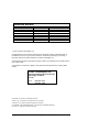
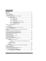
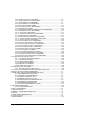


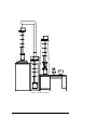
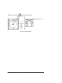
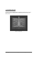


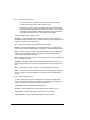
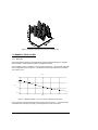
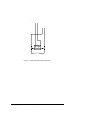
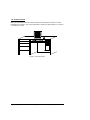
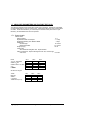

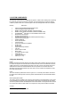
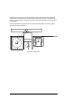
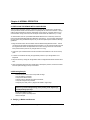

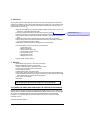

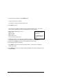
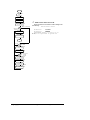

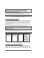
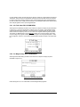
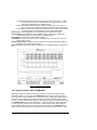
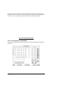


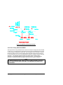
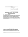

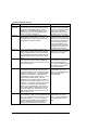


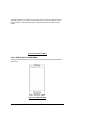

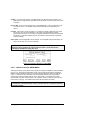
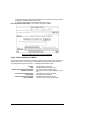


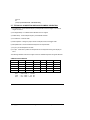


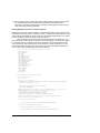


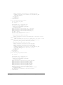
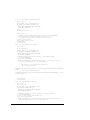
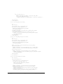


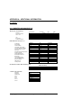


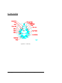
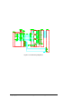
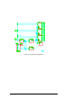
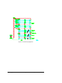
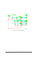


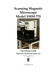


![IP Lock ライタ [IPL-003WR]取扱い説明書](http://vs1.manualzilla.com/store/data/006612445_3-78311d899b7484a4b21f6596cc5c8c15-150x150.png)