1
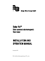
®
Badger Meter Europa GmbH
Solar-Flo™
Solar powered electromagnetic
flow meter
INSTALLATION AND
OPERATION MANUAL
November 2001
MID_SolarFlo_Bedienungsanleitung_0701_e.doc
Contents
Contents
Page
1.
Introduction
1
2.
Uncrating and inspection
1
3.
Tools required
1
4.
Site preparation
2
5.
Summary of installation options
2
6.
Installation
3
6.1
6.2
6.3
6.4
5
5
5
6
7.
Pipe mount, attached array
Pipe or pole mount, detached array
Solar deployment
Antenna mounting
Power-up
7.1
7.2
7.3
7.4
7.5
Step 1
Step 2
Step 3
Step 4
Step 5
6
7
7
7
7
7
8.
Operation
8
9.
Fuse replacement
8
MID_SolarFlo_Bedienungsanleitung_0701_e.doc
10.
Battery replacement
10.1
10.2
10.3
10.4
10.5
10.6
10.7
10.8
10.9
Step 1
Step 2
Step 3
Step 4
Step 5
Step 6
Step 7
Step 8
Step 9
8
9
9
9
9
9
10
10
10
10
11.
Solar voltage regulator
11
12.
Maintenance
11
MID_SolarFlo_Bedienungsanleitung_0701_e.doc
Introduction
1.
Page 1/12
Introduction
The Badger Meter Solar-Flo™ has specifically been designed to operate reliably
year round, in any kind of weather, almost anywhere in the world. The SolarFlo™ provides a viable solution to installation sites where conventional mains
power is unavailable, unreliable, or too expensive to install. During normal
operation it should require little or no maintenance, and should be inspected
once or twice a year.
2.
Uncrating and inspection
It is advisable to remove the protective cardboard cover on the sole panels and
inspect them for damage before signing the delivery ticket or bill of lading. You
should also inspect the outside of the enclosure, as well as the wire and
cabling for shipping damage. Although the Solar-Flo™ is a very rugged package
with a 30+ year design life, it can be damaged by a forklift or careless
handling. Look for signs that the pallet may have tipped over, or had been used
to push other cargo, as well as the obvious signs of torn shrink wrap, broken
banding or punctured cardboard. Any damage should be noted on the bill of
lading or delivery ticket before signing and accepting. Failure to do so will
severely limit your rights to a damage claim against the freight company.
3.
Tools required
Use a utility knife to cut the shrink wrap, plastic tape and plastic banding. A
9/16" wrench or socket is required to remove the pedestal from the plywood
base, or alternatively, a Philips head screwdriver can be used to remove the
plywood base from the pallet. It is suggested that for maximum stability and
safety the Solar-Flo™ be left on the pallet until it arrives at the installation site.
Move the palletized Solar-Flo™ with a forklift (preferred), or a pallet jack on
LEVEL GROUND ONLY. The top of the Solar-Flo™ enclosure has (2) 1" lifting
eyes if a crane or other overhead lifting device is used.
MID_SolarFlo_Bedienungsanleitung_0701_e.doc
Site preparation
4.
Page 2/12
Site preparation
Since the Solar-Flo™ will often be installed at remote, unattended sites, it is
essential that the installation be designed to endure the harshest weather
conditions imaginable. This might include earthquake, hurricanes and typhoons,
high winds, hail, driving rain, and ice and snow buildup, as well as the
occasional nearby lightning strike.
To accommodate various site conditions, and customer preferences, we offer
(5) pre-engineered site designs: concrete pad, steel pipe, wooden pole,
structural rack, and frost line foundation. The detailed drawings and
specifications provided should be adhered to closely, and attention to detail on
the site preparation will avoid future maintenance and service problems. It will
also assure the system provides the maximum reliability. For example, a
directional antenna that shades the solar array could seriously degrade the
solar panels performance, causing a likely failure due to low batteries.
5.
Summary of installation options
Concrete pad:
Simplest and most stable, should be used whenever
possible, quickest installation time.
Steel pole:
Works if directional antenna is required, or solar array
elevation or orientation is an issue. Requires concrete base
on larger systems for stability. 2" pipe recommended for
SF-120, 140, 160, 3" – 4" for 180 to 320. 4" – 6" for
420 and 480.
Wooden pole:
Recommended for low cost where soil is stable. If theft
and vandalism are an issue, wooden pole allows
elevated mounting of the enclosure and solar array.
Structural rack:
Works well on metal grating and sites where other flow
control devices require mounting, or higher elevation of
the system is required when using concrete pad.
Frost line:
Recommended where annual frost can heave the
foundation, possibly causing instability and leaning,
creating solar and antenna problems, among others.
MID_SolarFlo_Bedienungsanleitung_0701_e.doc
Installation
6.
Page 3/12
Installation
If no lifting equipment is available at the installation site, it is safe to remove
the batteries for ease of handling. If you elect the muscle to unit into place, try
to position the pallet as close to the concrete pad as possible (it is not
advisable to "muscle" the system into place if it is on a pole or pipe unless the
pedestal is resting on a base). Unscrew the (4) 3/8" anchor bolts down gently
until they drop out. Grasping the top of the enclosure firmly, "walk" the SolarFlo™ across the pallet to the pad. Place several 2x4 pieces on the pad so you
will clear the anchor bolts when you "walk" the Solar-Flo™ across the pad.
Position the mounting holes over the anchor bolts, then carefully tilt the unit to
remove the 2x4's, one side at a time, letting the unit down over the anchor
bolts.
When mounting the Solar-Flo™ on a concrete pad, it is preferable to lift the
entire unit using the (2) 1" lifting eyes at the top of the enclosure. A lifting eye
with two short lengths of chain, with a devise on each end is the preferred
method of lifting to avoid damage to the enclosure or solar array. DO NOT LIFT
THE UNIT BY THE SOLAR ARRAY. IF A FORKLIFT IS USED, SLIDE THE FORKS
TOGETHER AND APPROACH FROM THE DOOR SIDE, NOT THE SOLAR SIDE.
POSITION THE FORKS UNDER THE ENCLOSURE BETWEEN THE TWO STEEL
PEDESTALS. LIFT CAREFULLY, TAKING CARE TO NOT GO TOO FAR UNDER
WITH THE FORKS, OR THEY WILL DAMAGE THE SOLAR ARRAY. DO NOT
INSTALL THE SYSTEM WITH THE SOLAR PANELS DEPLOYED, AS IT WILL
HAVE A GREATER TENDENCY TO TIP.
VERIFY THE ANCHOR BOLT ORIENTATION WITH A COMPASS BEFORE
INSTALLING THE Solar-Flo™. THE BOLT PATTERN SHOULD MEASURE 18.50"
WX 11.25 FRONT TO BACK. THE FRONT TO BACK BOLTS SHOULD POINT
NORTH/SOUTH.
MID_SolarFlo_Bedienungsanleitung_0701_e.doc
Installation
Page 4/12
Solar panel side
(south)
1/2" – 13 anchor bolt
(4 PLCS)
11.25"
18.50"
Door side
(north)
ONCE THE GALVANIZED STEEL PEDESTAL FEET HAVE BEEN LOWERED OVER
THE 1/22 ANCHOR BOLTS, USE A STAINLESS STEEL FLAT WASHER, LOCK
WASHER AND HEX NUT PROVIDED TO SECURE THE SYSTEM. DO NOT
OVERTIGHTEN.
FOR PIPE AND POLE MOUNT INSTALLATIONS, ALWAYS INSURE THAT THE
SOLAR ARRAY FACES SOUTH (IN THE SOUTHERN HEMISPHERE THE PANELS
FACE NORTH). NEAR THE EQUATOR the panels should be tilted at least 10° to
avoid dirt accumulation. Most systems in the Continental U.S. will use a 45°
tilt, optimum for winter. Your solar array tilt angle will be preset at the factory
for unitized systems. Measuring the tilt angle is only an issue with pipe and
pole mounted systems.
MID_SolarFlo_Bedienungsanleitung_0701_e.doc
Installation
6.1
Page 5/12
Pipe mount, attached array
For pipe mount systems with an attached solar array, special
mounting brackets must be used to clear the pipe. These extended
brackets are extended 3" – 6" to accommodate the pipe running
vertically between the enclosure and solar array. This configuration
utilizes the solar array for shading to prolong battery life. A concrete
pad (without anchor bolts) is recommended to support the weight of
180W systems and larger, providing stability and keeping the pole
from leaning.
6.2
Pipe or pole mount, detached array
A pipe or pole mount system with a detached solar array is utilized
where the solar array must be mounted higher and separate from
the solar array. Orientation, theft resistant, solar access and
potential shading are among the reasons for a detached solar array.
The array should be oriented toward the equator, as discussed
earlier, with the distance between the top and bottom brackets
determining the correct angle.
6.3
Solar deployment
For pad mounted system, solar deployment is very quick and simple
once the system is bolted down. The two bolts holding the solar
array legs to the module frame are loosened and removed, and the
shipping ty-wraps are cut. One person holds the bottom of the solar
array, lifting up until the hole in the leg aligns with the lower hole in
the module frame. Replace the bolts and it's deployed.
To install a detached array, the upper crosspiece is clamped to the
pole with the stainless steel U-bolts provided. It is oriented E-West
so the solar array will face either true south (Northern hemisphere)
or true north (Southern hemisphere). Next, the vertical rails are
bolted to the top crossmember, allowing them to dangle. The lower
crosspiece is then clamped at the measured distance for the
particular site, according to latitude. This specific information is
included with each system, and the support angles form a 90° angle
with the pipe when deployed properly.
MID_SolarFlo_Bedienungsanleitung_0701_e.doc
Installation
6.4
Page 6/12
Antenna mounting
The antenna mounting referred to herein is for the Cybersensor
antenna only, although other antennas can be accommodated in a
similar fashion. The mounting bracket fort he Cybersensor antenna is
the short piece of UNISTRUT already bolted to the top of the
enclosure. The antenna cable has already been run and secured
under the stainless steel hold-down clips.
Adjust the antenna length to 37" as specified, and tighten the hose
clamp as directed in the antenna mounting instructions.
Mount the antenna to the UNISTRUT as described below, with the
hardware provided.
Connect the cable to the antenna, tighten gently, and slide the
weather boot up the cable and over the threaded connector to
discourage weathering and corrosion at the connection.
Visually check to be sure the antenna is straight up and down in
both directions (from the back and side). Recheck all fasteners and
connections for tightness.
7.
Power-up
During the power-up you will be connecting the batteries, solar panels, MAG
meter and Cybersensor link. The sequence in which you power-up is critical, if
you connect the wrong components out of sequence damage to the electronics
can result.
Note: Use the envelope marked "fuses" for power-up, not the spare fuses on
the door!
Always connect the battery first, and when powering down, disconnect it last.
Failure to do so can result in the electronics "seeing" open circuit solar panel
voltage, as high as 45 volts. The battery has (2) fuses, the main fuse on the
DIN rail, and the safety fuse at the farthest (+) positive battery terminal.
MID_SolarFlo_Bedienungsanleitung_0701_e.doc
Power-up
7.1
Page 7/12
Step 1
Connect the safety fuse first (15 A) by plugging it into the
waterproof socket, taking care not to bend the blades. Replace the
waterproof cap.
7.2
Step 2
Insert the battery fuse (10 A) on the DIN rail, taking care to insert it
in the proper slot.
7.3
Step 3
Plug in the white connector from the Cybersensor transmitter to the
battery pack.
7.4
Step 4
Install the MAG meter 5 A fuse and the Cybersensor 3 A fuse.
7.5
Step 5
Install the solar fuse (7.5 A to 20 A, depending on array size).
You may check system voltages at each fuse block with a digital volt
meter. If the sun is shining and the system is working properly you
should see the battery voltage slowly rise as the solar array charges
them. They will normally top off at approximately 28.2 volts, plus or
minus according to the temperature.
The system is now powered-up and operational. To POWER DOWN,
repeat the sequence in reverse order, that is: 1) Disconnect the
solar, 2) Disconnect Cybersensor and MAG meter, 3) Disconnect
Cybersensor battery pack, 4) Disconnect battery fuse, 5) Disconnect
safety fuse in battery compartment.
MID_SolarFlo_Bedienungsanleitung_0701_e.doc
Operation
8.
Page 8/12
Operation
Once the Solar-Flo™ is bolted down and powered up, there is little to do
except make sure the solar panels don't accumulate dust or bird poop. In most
climates, rainfall will keep the panels clean. Light dust is not a problem, but
heavy dust should be cleaned off, preferably at night when the panels won't
suffer thermal shock when the water hits them. The batteries should be
checked once or twice a year for signs of corrosion (see maintenance). Other
than that, there is little to do, as the solar system is designed to run
unattended for years.
9.
Fuse replacement
Occasionally, a fuse will blow, usually due to the wrong size or placement, and
sometimes when two battery packs are connected due to a current inrush to
the weaker pack. Normally, a blown fuse is visible, the area under the number
will turn black. You can check the fuse by placing your volt meter probes in the
screw holes above and below the fuse. Set the meter on Ω or diode, if the
ohms are higher or infinite the fuse is blown. If it doesn't beep in the diode
position, it's blown.
Before replacing it, measure the current across that fuse to determine if a
fault, short circuit or other problem exists. Put your meter on the DC 10 AMPS
setting and put the probes against the screws above and below the particular
fuse. Check the current, it should be within the specifications posted on the
fuse holder. If not, troubleshoot the wiring and equipment to find the problem.
10. Battery replacement
Periodically the batteries have to be replaced. Depending on climate, this will
occur every 3 years or so in hot weather, 5 to 7 in colder ones. It is
EXTREMELY IMPORTANT to replace the batteries with exactly what is
specified on the door of the enclosure. The wrong batteries may cause
chemical burns and equipment damage, may produce explosive gases, and can
cause a total system meltdown.
Note: Protective goggles or face mask, insulated tools and extreme caution
required!
MID_SolarFlo_Bedienungsanleitung_0701_e.doc
Battery replacement
Page 9/12
The only batteries acceptable for use in the Solar-Flo™ are those GEL or AGM
batteries manufactured by COMCORDE or EAST PENN. Battery sizes vary from
80 Ah to 130 Ah, always consult the door for the proper replacement.
10.1
Step 1
Power down the system. If continuous, uninterrupted service is
required, you may purchase a 24 volt back up battery with the
correct cables and diode to provide uninterrupted power during a
battery change out (see replacement parts, batteries).
10.2
Step 2
Remove battery fuse last at DIN rail, then remove the safety fuse at
the positive terminal.
10.3
Step 3
Remove the white interbattery jumpers (+ to -).
10.4
Step 4
Remove the positive and negative battery connections, and fold the
wires back slightly to avoid accidental arcing across the terminals.
Use extreme caution, even "dead" batteries can still pack
tremendous energy, enough to cause serious burns or an explosion
before you can react.
DO NOT CUT THE CABLE TIES HOLDING THE battery cables to the
battery hold down bar, they will serve as a convenient reminder of
how they go back.
10.5
Step 5
Loosen the 1/4" bolt holding the Unistrut to the stainless steel clip,
tilt the hold down bracket to clear the clip and bulkhead, and
carefully raise it out of the holder at the bottom of the enclosure.
Move the Unistrut battery hold down and cables out of the way so
you have clear access to the batteries.
MID_SolarFlo_Bedienungsanleitung_0701_e.doc
Battery replacement
10.6
Page 10/12
Step 6
Starting at the top, slide the batteries out, carefully, as they are
heavy (60 – 80 lbs), and can easily sprain limbs and break bones if
not handled properly. Set the old batteries aside, and make a quick
inspection of the battery compartment. Clean out any dirt, cobwebs
or debris that will hamper air circulation. Replace any damaged or
crushed foam.
10.7
Step 7
Replace the batteries and foam, starting at the bottom, carefully
moving the polarity and position of the battery terminals. Connecting
the batteries wrong can result in equipment damage and even fire,
so pay attention. When in doubt, consult the schematic on the door.
10.8
Step 8
Once the new batteries are installed, replace the battery hold down
bracket first. Make a visual check that the battery cables are red at
the positive terminals and black at the negative terminals (R side of
batteries). The left side jumpers (positive to negative) are white.
Do not overtighten the battery cable bolts in the battery terminal.
Since the terminals are soft lead, they will often take a "set" after a
short period of time. It is a good idea to retighten them after a few
hours, and check them periodically, but don't overtighten.
10.9
Step 9
Replace the safety fuse, then the DIN rail battery fuse, then the load
fuse, and the solar fuse last.
MID_SolarFlo_Bedienungsanleitung_0701_e.doc
Solar voltage regulator
11/12
11. Solar voltage regulator
For normal operation, power down, including the safety fuse. For
uninterrupted operation, jumper between the battery + and load +, and
battery – and load – before disconnecting the regulator. Once you are powered
down, loosen all 6 terminal screws, slip the wires out, starting with all the
negatives, then the positives. Be careful no to touch them if you are jumpered
in UPS mode. Remove the two nuts holding the regulator to the backplane,
slide it off the studs.
Replace the regulator with a new one, and repeat the procedure in reverse,
power-up as specified on the door.
12. Maintenance
When installed properly, the Solar-Flo™ requires little in way of maintenance,
other than an inspection every 6 – 12 months, check for solar panel fouling,
corrosion at the batteries, any signs of abuse or damage.
Batteries should be replaced according to your sites peak sun hour regime. The
reason is, the hotter the climate, the shorter the battery life, even with sun
shades and ventilation. Any time a "sealed" battery is exposed to high
temperatures, its lifetime is reduced due to the accelerated aging that takes
place.
Snug the battery terminal bolts annually during inspection, wear gloves and
goggles. Generally, the solar array does not require any maintenance, unless it
is subject to fouling (birds) or dust (nearby agriculture, construction, etc.). If
the solar panels require cleaning, wipe them with a soft damp cloth, or hose
them down at night. Do not hose them during the daytime as the cold water
may shatter the hot glass. A wet sponge is okay, rinse with clean water. If
perching birds are a problem (as they tend to face North in winter time,
placing their posterior over the solar panels) humane bird deterrents are
available.
Any corrosion on the battery terminals should be cleaned with a stainless steel
wire brush, again WEAR GOGGLES AND GLOVES. Clean the terminal and ring
lug on the cable(s), reassemble, coat with marine grade battery terminal
sealant, such as CORROSION-X etc. Always exercise caution when handling
live battery cables and wires, they can be very dangerous, and pose a shock,
burn and explosion hazard!
MID_SolarFlo_Bedienungsanleitung_0701_e.doc
Maintenance
Page 12/12
To replace a solar panel, simply remove the J-box cover, unscrew the internal
connections, noting the WIRING CONFIGURATION (sketch it!). Loosen the
cable gland and slip the wires out. Remove the 4 bolts holding the panel to the
frame. The factory replacement panel will be predrilled for the frame, unless
you bought it somewhere else to save money, then you may have to drill the
frame. Use a block of wood behind the frame as you drill it, otherwise, when
you punch through you'll drill into the back of the solar module, possibly
ruining it. Rebolt it, reconnect it, retighten. Check the solar array current
meter. Only bright summer sun will produce full solar array current.
MID_SolarFlo_Bedienungsanleitung_0701_e.doc
Hotline
Tel.
Fax
®
+49-7025-9208-0 or -30
+49-7025-9208-15
Badger Meter Europa GmbH
Subsidiary of Badger Meter, Inc.
Nürtinger Strasse 76
72639 Neuffen (Germany)
E-mail: [email protected]
www.badgermeter.de