1
®
Badger Meter Europa GmbH
Field Verification Device
for ModMAG® M2000 and
B-MAG™ I M5000
User manual
September 2011
MID_VD_BA_02_1109
Contents
Page
1. Basic safety recommendations ........................................................................................ 1
2. Verification Device ............................................................................................................. 2 2.1 Disclaimer .................................................................................................................. 2 2.2 Product identification information ............................................................................... 2 2.3 Product description .................................................................................................... 2 2.4 Functions ................................................................................................................... 2 2.5 Components............................................................................................................... 3
3. Cable connections ............................................................................................................. 4 3.1
Verification Device ..................................................................................................... 4
3.2
ModMAG® M2000 ...................................................................................................... 5
3.3
B-MAG™ I M5000 ...................................................................................................... 7
4. Display and keypad ............................................................................................................ 9
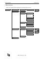
5. Menu structure ................................................................................................................. 10
6. Settings ............................................................................................................................. 11
7. Tests .................................................................................................................................. 13 7.1
Main test .................................................................................................................. 13
7.2
Manual tests............................................................................................................. 14
7.2
Amplifier test ............................................................................................................ 14
7.3
Detector test............................................................................................................. 14
7.5
Main test fails ........................................................................................................... 15
7.6
Meter identification ................................................................................................... 15
7.7
About........................................................................................................................ 15
8. PC software....................................................................................................................... 16 8.1 Installation of the PC software ................................................................................. 16 8.2 Download of the verification tests ............................................................................ 17 8.3 Print reports ............................................................................................................. 18 8.4 Export reports .......................................................................................................... 18 8.5 Language selection .................................................................................................. 19
9. Technical data .................................................................................................................. 20 9.1 Features ................................................................................................................... 20 9.2 Accessories.............................................................................................................. 20 9.3 Accuracy .................................................................................................................. 20 9.3.1 Amplifier ........................................................................................................ 20 9.4.2 Detector ........................................................................................................ 20
10. Return of goods for repair ............................................................................................. 21 MID_VD_BA_02_1109
Basic safety recommendations
Page 1 / 21
1. Basic safety recommendations
Before installing or using this product, please read this instruction manual thoroughly.
Only qualified personnel should install and/or repair this product. If a fault appears,
contact your distributor.
Installation
Do not place any unit on an unstable surface that may allow it to fall.
Never place the units above a radiator or heating unit.
Route all cabling away from potential hazards.
Isolate from the mains before removing any covers.
Power connection
Use only the type of power source suitable for electronic equipment. If in doubt, contact
your distributor. Ensure that any power cables are of a sufficiently high current rating.
All units must be earthed to eliminate risk of electric shock.
Failure to properly earth a unit may cause damage to that unit or data stored within it.
Protection class
The device has protection class IP 46 and needs to be protected against dripping water,
water, oils, etc.
Setup & operation
Adjust only those controls that are covered by the operating instructions. Improper
adjustment of other controls may result in damage, incorrect operation or loss of data.
Cleaning
Switch off all units and isolate from mains before cleaning.
Clean using a damp cloth. Do not use liquid or aerosol cleaners.
Repair of faults
Disconnect all units from power supply and have it repaired by a qualified service person if
any of the following occurs:
• If any power cord or plug is damaged or frayed
• If a unit does not operate normally when operating instructions are followed
• If a unit exposed to rain/water or if any liquid has been spilled into it
• If a unit has been dropped or damaged
• If a unit shows a change in performance, indicating a need for service.
Failure to adhere to these safety instructions
may result in damage to the product or serious
bodily injury.
RoHs
Our products are RoHs compliant.
Battery disposal
The batteries contained in our products need to be disposed of as per your
local legislation acc. to EU directive 2006/66/EG.
MID_VD_BA_02_1109
Verification Device
Page 2 / 21
2. Verification Device
2.1 Disclaimer
The user/purchaser is expected to read and understand the information provided in
this manual, follow any listed safety precautions and instructions and keep this
manual with the equipment for future reference.
The information in this manual has been carefully checked and is believed to be
entirely reliable and consistent with the product described. However, no responsibility
is assumed for inaccuracies, nor does Badger Meter assume any liability arising out
of the application and use of the equipment.
Should the equipment be used in a manner not specified by Badger Meter, the
protection provided by the equipment may be impaired.
2.2 Product identification information
Record the product identification numbers from the nameplate.
Modular Mag Meter
Model Number M5000________________________________
Serial number ______________________________________
Tag number
(if applicable)
2.3 Product description
Field Verification Device is a portable test device for the electromagnetic flow meters
type ModMAG® M2000 and the B-MAG™ I M5000.
With the Field Verification Device, accurate verification of meter functionality is
assured without taking the meter out of the pipeline ("wet" test) and interrupting
functionality. Meter diagnosis and calibration can be performed on-site. A "dry" test
(removing the meter and benchtesting) can also be performed. The complete
verification test consumes approximately 20 minutes and results can be downloaded
to a Microsoft Windows® personal computer.
2.4 Functions
The Verification Device also:
• determines if the meter is within one percent of the original factory
calibration.
• verifies the functionality of all of the meter's inputs and outputs.
• measures electrode resistance and integrity.
• measures coil resistance and integrity.
• measures coil insulation resistance.
• measures current and frequency at previously selected flow rate.
• evaluates the signal processing functionality.
• verifies that there is no high-voltage noise disturbing the coil circuit.
MID_VD_BA_02_1109
Verification Device
Page 3 / 21
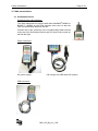
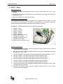
2.5 Components
The Field Verification Device is packaged in a foam-lined, durable, plastic case and
includes the following components:
1 2 pcs. verification cable harnesses: One for the ModMAG® M2000 and one for
the B-MAGTM I M5000 meters.
2 4 pcs. AC power conversion connectors
3 1 pc. DC power adapter
4 1 pc. amplifier AC power cord
5 1 pc. Verification Device +5 VAC, 3.0A power supply
MID_VD_BA_02_1109
Cable connections
Page 4 / 21
3. Cable connections
3.1 Verification Device
Connecting the cable harness:
The cable harnesses are tagged with either ModMAG® M2000 or
B-MAG™ I M5000 on the outer harness wire cover so that the
user can differentiate between the two.
Connect the 25 pin connector of the corresponding cable harness
to the top of the Verification Device and fix it by the two screws on
the left and right.
Power connector:
AC power supply
Car charger via USB cable (DC power)
USB connector:
MID_VD_BA_02_1109
Cable connections
Page 5 / 21
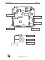
3.2 ModMAG® M2000
Switch off the amplifier before connecting the cable harness of the Verification
Device.
Opening the cover:
1. Using a 1/4" slotted screwdriver, remove the two right-hand screws from front of
the amplifier.
2. Loosen the two left-hand screws until the screw heads protrude above the surface
of the amplifier door.
3. Open the amplifier door from right side to left.
Connecting the cable harness:
The individual connector wires are labeled as to where each connector is to be
connected onto the internal circuit board of the amplifier. A connection instruction
label has been placed inside of the amplifier for connection reference.
On ModMAG® M2000 cable harness are following connectors:
1.
2.
3.
4.
5.
6.
7.
8.
Output 1 & 2 / RS232 (7 pins)
Output 3 & 4 / Input (7 pins)
Analog output (2 pins)
Detector electrode (6 pins)
Detector coil (3 pins)
Amplifier electrode (6 pins)
Amplifier coil (3 pins)
Detector ground (alligator clip)
Harness connections
1.
2.
3.
4.
5.
6.
7.
8.
Clip the alligator clip labeled "Detector Ground" to either of the hex nuts mounted
on top of the meter flanges.
Plug the connector labeled "Amplifier Electrode" into the circuit board connector
labeled "E1, ES, E2, RS, EP, ES".
Plug the "Amplifier Coil Output" into the circuit board connector labeled "CS, C2,
C1."
Plug the "Output 1 & 2/ RS232" into the board output connector labeled "1 to 7."
Plug the Output 3 & 4 / Input" into the board output connector labeled "1 to 14".
Plug the "Analog output" connector into the board connector labeled "15 and 16"
in connector row of "COMMUNICATION / Analog out" on the right side.
Connect the harness wire connector labeled "Detector Electrode" to the 6-wire
connector from the detector.
Connect the harness wire connector labeled "Detector Coil" to the 3-wire
connector from the detector.
MID_VD_BA_02_1109
Page 6 / 21
L
N
PE
Cable connections
Amplifier coil
JP1
1
2
3
4
5
6
7
CS
C2
C1
DISPLAY
Output 1 & 2 / RS232
JP2
8
9
10
11
12
13
14
BA2000-22MID
Output 3 & 4 / Input
15
16
E1
ES
E2
RS
EP
ES
COMMUNICATION
Amplifier electrode
Analogue output
13 Shield
12 C2
11 C1
Detector coil
45 E1
44 Shield
46 E2
44 Shield
40 EP
44 Shield
Detector electrode
Detector ground
From
detector
MID_VD_BA_02_1109
Cable connections
Page 7 / 21
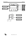
3.3 B-MAG™ I M5000
Opening the cover:
1. Using a 1/4" slotted screwdriver, remove the two top screws from front of the
amplifier.
2. Loosen the two bottom screws until the screw heads protrude above the surface of
the amplifier door.
3. Open the amplifier door from top to bottom.
Connecting the cable harness:
The individual connector wires are labeled as to where each connector is to be
connected onto the internal circuit board of the amplifier. A connection instruction
label has been placed inside the amplifier for connection reference.
On B-MAG™ I M5000 cable harness are following connectors:
1. RS232 (4 pins)
2. Output 1 (2 pins)
3. Output 2 (2 pins)
4. Output 3 (2 pins)
5. Output 4 (2 pins)
6. Detector electrode (5 pins)
7. Detector coil (2 pins)
8. Amplifier electrode (5 pins)
9. Amplifier coil (2 pins)
10. Detector ground (alligator clip)
Harness connections:
1.
Clip the alligator clip labeled "Detector Ground" to either of the hex nuts mounted
on top of the meter flanges.
2. Plug the connector labeled "Amplifier Electrode" into the circuit board connector
labeled "E1, ┴, E2, ┴, EP".
3. Plug the "Amplifier Coil Output" into the circuit board connector labeled " C1, C2."
4. Plug the "Output 1" into the board output connector labeled "Out1".
5. Plug the "Output 2" into the board output connector labeled "Out2".
6. Plug the "Output 3" into the board output connector labeled "Out3".
7. Plug the "Output 4" into the board output connector labeled "Out4".
8. Plug the “RS232" into the board output connector labeled "RS232".
9. Connect the harness wire connector labeled "Detector Electrode" to the 5-wire
connector from the detector.
10. Connect the harness wire connector labeled "Detector Coil" to the 2-wire
connector from the detector.
MID_VD_BA_02_1109
Cable connections
Page 8 / 21
Rx
Tx
GND
+
OUT 4
+
- OUT 3
Amplifier electrode
+
OUT 2
+
OUT 1
-
Amplifier coil
COIL
Detector coil
ELECTRODE
Detector electrode
Detector ground
From
detector
MID_VD_BA_02_1109
RS232
Output 4
Output 3
Output 2
Output 1
Display and keypad
Page 9 / 21
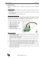
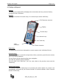
4. Display and keypad
Display:
The display is a backlit LCD and displays the current date and time, percent of battery
charge and menu indications.
Keypad:
The keypad consists of 9 function keys, 12 numerics keys and the On/Off key.
D-25 harness connector
Display
Function keys
Numeric keys
Power key
USB
connector
AC Power connector
Power key:
The power key on the lower right applies or remove power to the Verification Device.
Function keys:
The 2 top “soft” keys on the left and right sides of the up arrow key provide menu access,
wet or dry detector selection.
The up, down, left and right keys allow menu navigation.
The “OK” key confirms a menu selection.
The left arrow is the “Back key” (you can return back to the previous menu) and the
“Delete key”.
Alphanumeric keys:
The primary purpose of these keys is for entering the serial number of a meter if not
automatically recognized by the internal firmware or external software. Other functions
include Test ID entry.
MID_VD_BA_02_1109
Menu structure
Page 10 / 21
5. Menu structure
Refer to the following when navigating the Verification Device menus:
Start Menu
Main Test
Test ID
Flow Meter
Flow Meter Ident
Amplifier
Detector
Dry
Wet
Detector Current
Analogue
Input
Analog Input
Analogue
Output
Analog Output
Inputs/Outputs
Empty Pipe
Detector
Coil Resistance
Electrode Impedance
Isolation
Main Test fail
Settings
Miscellaneous
Language
Contrast
Date
Time
Modbus Adress
About
MID_VD_BA_02_1109
English
Czech
Russian
Rusian
German
Spanish
Settings
Page 11 / 21
6. Settings
Press the “On/Off” button on the Verification Device and wait for the “SelfTest” to
complete, which lasts a couple of seconds.
After that, following display appears and shows date, time, battery capacity and firmware
version. Check if date and time are correct because the test reports are stored and printed
with those data.
When the Start Menu appears on the display, press the upper left function key.
Language
1. Select a menu item from the StartMenu > Menu User > Settings > MISC > Language
with the upper right function key.
2. Select the appropriate language (the default language is English).
Date
1. Select a menu item from the StartMenu > Settings > Misc > Date.
2. Edit the day, month and year in the editbox by using the numeric keypad. Use the right
arrow key to move the cursor.
3. Confirm the new date with the upper right function key.
Time
1. Select a menu item from the StartMenu > Settings > Misc > Time.
2. Edit the hour and minutes in the editbox by using the numeric keypad. Use the right
arrow key to move the cursor.
3. Confirm the new date with the upper right function key.
MID_VD_BA_02_1109
Settings
Page 12 / 21
Contrast
Adjust the contrast of the display via the function keys (arrows) and save the adjustment
with “Yes”
Flow meter Modbus® address
1. Select a menu item from the StartMenu > Settings > FM Modbus® address.
2. Edit the address in the editbox by using the numeric keypad. Use the “Delete” arrow
key to remove the last number position.
3. Press the upper right function key to confirm the new address.
4. Be sure that the flow meter is programmed with the same Modbus® address otherwise
communication fail. Default address is 1.
MID_VD_BA_02_1109
Tests
Page 13 / 21
7. Tests
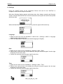
7.1 Main test
The main test is the standard process for meter testing. The result of this test is
automatically stored in the memory of the Verification Device and can be downloaded
from the PC program.
The procedure is the following one:
1. Switch off the flow meter and connect the specific wire harness to the amplifier
circuit board.
2. Connect the male D-25 connector of the harness to the corresponding female
connector on the Verification Device.
3. Switch on the flow meter and be sure that the meter is not in the programming
mode when the test starts.
4. Press the “On/Off” button on the Verification Device and wait for the “SelfTest” to
complete.
5. When the Start Menu appears on the display, press the upper left function key.
6. When the Main Test option is highlighted, press the “OK” button.
7. Press the appropriate numbers on the numeric keypad for the Test ID and press
“OK”. The Test ID is a value which can be used as a customer tag.
8. Select if the detector tube is inside dry or wet. This selection has influence on the
test results of the electrode measurement.
9. The tests are now automatically carried out in 10 steps. During the test, the flow
meter shows “Testing in progress” on the display.
10. The result will be “passed” or “failed”.
11. If the test failed, press the function key on the upper left “View Report” to see the
results. See example below.
MID_VD_BA_02_1109
Tests
Page 14 / 21
7.2 Manual tests
The result of the manual tests are not stored in the memory of the Veriification Device
and cannot be downloaded from the PC program.
1. Switch off the flow meter and connect the specific wire harness to the amplifier
circuit board.
2. Connect the male D-25 connector of the harness to the corresponding female
connector on the Verification Device.
3. Switch on the flow meter and be sure that the meter is not in the programming
mode when the test starts.
4. Press the “On/Off” button on the Verification Device and wait for the “SelfTest” to
complete.
5. When the Start Menu appears on the display, press the upper left function key.
6. Select the menu “Flow Meter” and press the “OK” button
7.2 Amplifier test
• Detector current
The current [A] and excitation frequency [Hz] are measured
• Analog input
Amplification and linearity is measured [div/V]
• Analog output
Offset and linearity is measured [mA]
• Inputs/Outputs
The in- and ouput function are tested as well as output frequency [Hz]
• Empty pipe
7.3 Detector test
• Coil resistance
Measures the resistance of the coils [Ohm]
• Electrode impedance
Measures the impedance of the 3 electrodes (measuring and empty pipe) in [Ohm]
• Isolation
Measures the resistance of the coils against ground [Ohm]
MID_VD_BA_02_1109
Tests
Page 15 / 21
7.5 Main test fails
Shows the test result of the last main test.
7.6 Meter identification
The menu display information about the connected flow meter.
•
•
•
•
•
•
Product name
Serial number
Firmware name and version
Compilation date
Otp Boot Checksum
Flash Os Checksum
7.7 About
Information about your Verification Device
• Serial number
• Version
• Compilation date
• FlashOsChecksum
• MCU revision
• Date of last detector current calibration
• Date of last coils resistance calibration
• Date of last analog output calibration
• Date of last analog input calibration
MID_VD_BA_02_1109
PC software
Page 16 / 21
8. PC software
8.1 Installation of the PC software
Insert the delivered CD, open “setup.exe” and follow the instructions. An icon on
the desktop will be installed named “Verification Device”.
MID_VD_BA_02_1109
PC software
Page 17 / 21
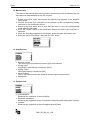
8.2 Download of the verification tests
1. Start the PC program by pressing the “Verification Device” icon on your desktop.
2. Connect the Verification Device via the USB cable to the PC and switch the device
“On”. The display on the device shows “USB Mass Storage”
3. The following PC window will automatically be opened. Select the device and
press OK. If the window does not open, click FILE and OPEN (Ctrl+O) in the upper
task line.
4. The measurements are automatically downloaded to the PC. You will be asked if
the measurements which are on the Verification Device should be deleted or not.
5. The downloaded measurements are displayed on the left side of the window.
6. Select the new measurements and enter following information for each test.
Customer tag is already given by enter the “Test ID” during the testing with the
Verification Device. Click button “Save changes” to save the entries.
MID_VD_BA_02_1109
PC software
Page 18 / 21
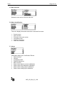
8.3 Print reports
1. Select the measurement which you want to print out
2. Click FILE and PRINT
3. A preview window appears:
4. Click printer symbol for print out.
8.4 Export reports
1. Select “Export all” for all or “Export selected” for exporting one measurement.
2. Save the data in “CSV” format to be imported in MS Excel.
MID_VD_BA_02_1109
PC software
Page 19 / 21
8.5 Language selection
1. Select TOOLS and OPTIONS
2. The “Tools” menu opens a language (default is English).
MID_VD_BA_02_1109
Technical data
Page 20 / 21
9. Technical data
9.1 Features
The Field Verification Device
• determines if the ModMAG® M2000 or B-MAG™ I M5000 is within one percent of
the original factory calibration.
• verifies the functionality of all of the meter’s inputs and outputs.
• measures electrode resistance and integrity.
• measures coil resistance and integrity.
• measures coil insulation resistance.
• measures current and frequency at previously selected flow rate.
• evaluates the signal processing functionality.
• verifies that there is no high-voltage noise disturbing the coil circuit.
• provides certified printout showing test results.
• is capable to store 100 meter tests.
9.2 Accessories
•
•
•
•
•
•
Test cable for ModMAG® M2000 connection
Test cable for B-MAG™ I M5000 connection
AC charger with EU/US connection adaptors
Automobile utility DC power supply connector
PC communication cables to Verification Device
Pelican suitcase for transport
9.3 Accuracy
9.3.1
Amplifier
Input gain
Excitation coil current
Excitation coil frequency
Analogue outputs current
Digital outputs
9.4.2
± 0,1%
20-400mA; ± 0,1%
50/60Hz; ± 1%
4-20mA; ± 0,1%
1Hz/20 kHz; – 0,1%
Detector
Coil resistance
Electrode resistance
(against ground)
Coil insulation
(against ground)
40-120 Ohm +/-1 %
100 kOhm-10 MOhm; +/-10 %
100 kOhm-10 MOhm; +/-10 %
MID_VD_BA_02_1109
Return of goods for repair
Page 21 / 21
10. Return of goods for repair
Please copy, fill in and sign hereafter harmlessness declaration and enclose it for any return
of goods you may send back for repair.
No repair will be performed prior to receiving the harmlessness declaration duly filled and
signed.
Harmlessness declaration
To
:
__________________________________________________________________
Attn.
:
__________________________________________________________________
From
:
__________________________________________________________________
Dept.
:
__________________________________________________________________
Please note that no repair will be performed prior to receiving of this declaration duly
signed by you!
Please send all parts clean from medium and inform us about possible medium wastes
remaining in the part. For this purpose, please use this form. A security specification sheet of
the medium must accompany this declaration in the following cases: Toxical, dangerous or
objectionable media, or media belonging to any dangerous materials class. We inform you
that uncleaned parts lead to additional costs. Extra clean costs will be charged to you.
Declaration
We herewith confirm that the part(s) sent for repair has/have been cleaned and is/are free of
any liquid and/or solid wastes of the medium and/or cleaning medium: Any eventually
remaining wastes are:
harmless
dangerous, toxic, etc. – Security specifications are attached
Signature of person in charge:
______________________________________
Name of the person in charge in capital letters: ______________________________________
Date:
______________________________________
Company stamp:
______________________________________
MID_VD_BA_02_1109
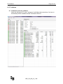
Relais
3 1
0/4…20mA
250
0/2…10mA
geschlo
Normal
offen
Stromausg
Vorwärts
Frequenza
48
Relais
VmA
Relais
2
Durch
Durchflußrichtung
rückw
Durchflußrichtung
ang
(aktiv)
500
mA rückw
usgang
tsRelais 1
(passiv)
Skalenendwert
Hotline
Phone +49-7025-9208-0 or -30
Fax
+49-7025-9208-15
®
Badger Meter Europa GmbH
Subsidiary of Badger Meter, Inc., USA
Nürtinger Strasse 76
72639 Neuffen (Germany)
E-mail: [email protected]
www.badgermeter.de