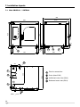
1
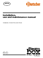
GB/UK Installation, use and maintenance manual COMBINED, CONVECTION AND STEAM H T ver. 04/2013 Table of Contents 1.Installation 1.1.General and safety warnings 1.2.Positioning 1.3.Adjustment of hinges and closing pin of the door 1.4.Water connection 1.4.Drain connection 1.6.Electric connection 1.7.Gas connection 1.8.Fumes exhaust 1.9.Operating values of gas ovens 1.10. Oven start-up and testing 2. Use instructions 2.1.Preliminary information Start/stop-switch-off-lighting 2.2. Choice of cooking method 2.3.Setting of temperature 2.4 Time setting 2.5.Humidity - Steam tuner 2.6. Fan speed 2.7. Cooking with core probe 2.8.Rack Control cooking 2.9.Holding 2.10. Cooling during cooking 2.11. Cooling compartment 2.12. Humidity draining valve 2.13. Recipes 3. Service Menu 3 3.7. Language 37 3 3 3.8. Advanced services 38 3.9. Import/Export recipes 39 5 6 6 7 9 10 11 13 4.Maintenance 40 4.1. Cleaning 40 4.2. Humidity draining 41 4.3. Glass cleaning 41 4.4. Cleaning of air filter 41 5. Components for control and safety 5.1.Solenoid valve 5.2.Door magnetic micro-switch 5.3.Motor thermal protection 5.4.Safety thermostat of the cooking compartment 5.5.Flame control 14 14 15 16 17 18 19 20 21 22 24 25 26 27 28 6. What to do if 6.1.Common problems 6.2.Checks to be carried out only by an authorised technician 6.3.Spare parts management 7. Installation layouts 7.1. 42 42 42 42 42 42 43 43 44 45 46 Mod. SBHE061 / SBTE061 46 7.2. Mod. SBHG061 / SBTG061 47 7.3. Mod. SBHE101 / SBTG101 48 49 31 7.4. Mod. SBHG101 / SBTG101 3.1.Manual/automatic washing 31 7.5. Mod. SBHE102 / SBTE102 50 3.2.Descaling 33 7.6. Mod. SBHG102 / SBTG102 51 3.3.Date and time 34 7.7. Mod. SBHE201 / SBTE201 52 35 7.8. Mod. SBHG201 / SBTG201 53 3.5. Backlight 35 7.9. Mod. SBHE202 / SBTE202 54 3.6. System info 36 3.4. Parameters 7.10. Mod. SBHE202 / SBTG202 8. Alarms description 55 56 Dear Customer, We thank you for having purchased our product. This oven is part of a line of appliances specifically designed for baking and patisserie, made of gas and electric ovens with different capacities. The pleasant and modern design of these ovens encloses ease of use, ergonomics and cooking control. The oven has a 12 months warranty against any manufacturing faults, starting from the date on the sales invoice. The warranty covers the normal functioning of the oven and does not include the consumption materials (lights, gaskets, etc.) and faults caused by incorrect installation, wear, maintenance, repair, decalcification and cleaning, tampering and improper use. 2 1. Installation 1.1. General and safety warnings Carefully read this manual before installing and commissioning the oven, in that the text gives important indications regarding the safe installation, operating and maintenance of the equipment. Keep this manual in a safe and easily accessible place for further consultation by the operators. In case of transferring the oven, always attach the manual; if necessary, a new copy must be requested from the authorised dealer or directly from the manufacturing company. Once unpacked, ensure the oven is intact and does not show signs of damage due to transport. A damaged appliance must never be installed and commissioned; if in doubt, immediately contact the after-sales technical assistance or your own dealer. Installation, extraordinary maintenance and repair operations on the equipment must only be carried out by professionally qualified staff and by following the manufacturer instructions. The appliance has been designed to cook food in closed premises and must only be used for this purpose: any other different use must, therefore, be avoided as considered improper and dangerous. Children must be supervised to assure they do not play with the appliance or use it. Pay attention to the hot parts of the external surfaces of the equipment during functioning that, in working conditions, may exceed 60°C. In case of fault or bad functioning, the equipment must be deactivated; in case of repair, contact only an after-sales technical assistance centre authorised by the manufacturer and request original spare parts. Do not position other heat sources like, for example, fryers or hotplates, near the oven. Do not deposit or use flammable substances near the equipment. In case of prolonged disuse of the appliance, both the water and electric energy supply must be shut-off. Before commissioning the equipment, ensure to have removed all packaging, being careful to dispose of it in compliance with the Standard in force. Every amendment to oven installation that should result necessary, must be approved and carried out by authorised technical staff. The oven must only be used by staff adequately trained for its use. To avoid the risk of accidents or damages to the appliance, it is also fundamental that staff regularly receive precise instructions regarding safety. The device is intended for professional use only by qualified personnel. The oven must not be used by persons with reduced physical, sensorial or mental capacities or by persons without experience and knowledge, unless supervised or educated regarding the operating of the appliance by a person responsible for their safety. Amendments to the oven wiring are not admitted. When the cooking cavity is hot pay attention to the door opening. BURN HAZARD!! The non-compliance with the above warnings can jeopardise the safety of the equipment and yours. The appliance must be positioned in an area with adequate ventilation to prevent an excessive accumulation of harmful substances in the air of the room where it is installed. 3 STEAM-BOX. Installation, use and maintenance manual 1. Installation 1.1. General and safety warnings The gas oven versions are compliant with essential requisites of Gas Directive 2009/142/EEC and are, therefore, provided with CE review certification issued by a Notified body. They satisfy the prescriptions of the following gas Standards: EN 203 + subsequent updates; EN 437 + subsequent updates. For installation the safety prescriptions contained in the following must be complied with: Standards UNI CIG n. 7222-7723-8723 + subsequent amendments. The equipment is compliant with the essential requisites of Low Voltage Directive 73/23/EEC and 2006/95/EEC. It satisfies the prescriptions of the following electrical Standards: EN 60335-1 + subsequent updates; EN 60335-2-42 + subsequent updates; EN 55104 / EN 55014 + subsequent updates; EN 61000 + subsequent updates. The equipment is compliant with the essential requisites of Electro-magnetic Compatibility Directive. 1.2. Positioning The appliances have been designed for installation in closed premises, they cannot be used in the open air and cannot be exposed to rain. The place of installation of the oven must have a solid, flat and horizontal surface able to safely support both the mass weight of the appliance/support and that of maximum load capacity. The appliance must be positioned in an area with adequate ventilation to prevent an excessive accumulation of harmful substances in the air of the room where it is installed. The oven must only be installed on a stable support. The appliance must be removed from its packaging, its integrity checked and arranged in the place of use, being careful not to position it above or against walls, sides, partition walls, kitchen cabinets or covers in flammable material. We recommend scrupulously complying with the fireproof Standard in force. fig. 1 4 There must be a minimum distance of 50 mm on all sides between the oven and the walls or other equipment. We recommend leaving 500 mm of space between the left side of the oven and the corresponding room wall (fig. 1), for easy oven installation and its subsequent maintenance. 1. Installation 1.2. Positioning All materials used for packaging are compatible with the environment; they must be safely kept and disposed of according to the Standard in force. The oven must be levelled: to regulate the height of the adjustable feet act, using as reference a spirit level, as shown in fig. 2. Significant unevenness or inclinations can negatively influence the functioning of the oven. Slowly remove all protective film from the appliance external panels, being careful not to leave traces of adhesive. Check that the heat disposal or inlet slots and openings are not obstructed. fig. 2 1.3. Adjustment of the hinges and closing pin of the door Once the oven has been correctly positioned in its designated place for installation, check the closing and seal of the gaskets on the oven compartment door. The door hinges must be adjusted to assure maximum seal of the oven door during its functioning. It is possible to adjust both the upper and lower hinges. fig. 3 If required, to adjust the door seal, loosen the bolt (fig. 3) and move the door in wanted position. Once adjusted, fasten the bolt again. The depth of the door's closing pin can be adjusted to eliminate any steam emissions during cooking. Tightening° the pin increases door pressure against the gasket, and unscrewing the pin decreases it. Once adjusted, fasten the bolt again ensuring to have positioned the lock closing anchoring downwards. fig. 4 5 STEAM-BOX. Installation, use and maintenance manual 1. Installation 1.4. Water connection The water pressure must be max. (250 KPa) 2.5 bar. Should the water pressure from the mains be higher than such value, install a pressure reducer upstream of the oven. The minimum water temperature for the correct functioning of the oven must be higher than 0.5 bar. The oven has a softened water inlet (fig. 5). Always install a water softener to bring the hardness of the water at appliance inlet within the values of between 8° and 10° F. Before connecting, let sufficient amount of water flow to clean the duct from any iron residues. Connect the "Water" duct to the specific cold water mains, and interpose a shut-off cock and filter. Ensure the shut-off cock is located in a place and in a manner to be easily activated at any moment by the operator. fig. 5 Attention: in case of water drain pipe fault, it must be replaced with a new one and the old and faulty one must never be re-used. 1.5. Drain connection A The oven is equipped with a water draining device; such device is located at the bottom in the rear part of the appliance and has a tube with a 28 mm diameter. Connect the tube that protrudes from the draining device (fig. 6, ref. A). The draining device is a siphon; we recommend connecting the tube on an open funnel. Check that the internal siphon is full of water and, if not, fill it by introducing H2O through the drain in the cooking compartment. fig. 6 6 1. Installation 1.6. Electric connection MOD SBHE061 P04E NR 3N 400V AC 50 HZ POWER SUPPLY OVEN POWER kW 000000/01/08 10,0 BOILER POWER kW 11,0 11,4 TOT. POWER kW 1,0 IP fig. 7 The electric system, as prescribed and specified by the Standard in force, must be equipped with an efficient ground. It is possible to guarantee the electric safety of the appliance only in the presence of Standard electric system. Before carrying out the electric connection, the voltage and frequency values of the mains must be checked to verify they are compliant with the appliance requirements indicated on the technical plate (fig. 7). For direct connection to the mains it is necessary to interpose a device between the equipment and the same mains, dimensioned depending on the load, that ensures its disconnection and which contacts have an opening distance enabling the full disconnection in the conditions of over-voltage category III, in compliance with the installation regulations; this device also must be located in a place and in a manner to be easily accessible at any moment by the operator. Bring the main switch, to which the power supply cable plug will be collected, in position 0 (zero). Have professionally qualified staff check that the plug cables' section is adequate to the power absorbed by the appliance. Loosen the screws fixing the left side of the oven and extract it (fig. 8). fig. 8 The flexible cable must be made of polychloroprene or synthetic elastomer under equivalent oil-resistant sheath. Use a cable with adequate section to the load corresponding to every appliance, as shown in the table (tab. 1). Models SBHE061 SBTE061 SBHE101 SBTE101 SBHE102 SBTE102 SBHE201 SBTE201 SBHE202 SBTE202 Voltage 3N 400V 3N 400V 3N 400V 3N 400V 3N 400V 3N 400V 3N 400V 3N 400V 3N 400V 3N 400V Frequency 50 50 50 50 50 50 50 50 50 50 Absorbed power (kW) 11.4 10.4 16.7 15.7 28.3 25.8 33.3 30.8 54.1 51.6 Cable section power supply (mm2) 5 x 2.5 5 x 2.5 5x4 5x4 5x6 5x6 5 x 10 5 x 10 5 x 10 5 x 10 Models SBHG061 SBTG061 SBHG101 SBTG101 SBHG102 SBTG102 SBHG201 SBTG201 SBHG202 SBTG202 Voltage 1N 230V 1N 230V 1N 230V 1N 230V 1N 230V 1N 230V 1N 230V 1N 230V 1N 230V 1N 230V Frequency (Hz) 50 50 50 50 50 50 50 50 50 50 Absorbed power (kW) (Hz) 12+1.4 12+0.4 19+1.7 19+0.7 28+3.3 28+0.8 38+3.3 38+0.8 56+4.1 56+1.6 Cable section power supply (mm2) 3 x 1.5 3 x 1.5 3 x 1.5 3 x 1.5 3 x 1.5 3 x 1.5 3 x 1.5 3 x 1.5 3 x 1.5 3 x 1.5 tab. 1 7 STEAM-BOX. Installation, use and maintenance manual 1. Installation 1.6. Electric connection Electric ovens L1 L2 L3 table 2 N Gas ovens For the electric connection, refer to the electric layouts in the appendix to this manual. L Place the power supply cable inside the cable gland hole in the lower part, on the left of the oven. N Between phase and there must be a potential difference of 230 V. Connect the cable to the terminal board following the indications in tab. 2. Lock the cable with the cable gland. The power supply voltage with machine functioning, must not be different from the nominal voltage value of ±10%. The equipment must be included in an equipotential system which efficiency must be checked according to that reported in the Standard in force. For the connection there is a clamp, located on the frame and marked with the symbol of fig. 9, to which a cable with minimum section of 10 mm² must be connected. fig. 9 8 For gas ovens, complete gas connection to the appliance before assembling the oven side again; for electric ovens assemble the oven side. 1. Installation 1.7. Gas connection (only for gas ovens) Nota bene The oven is originally calibrated for functioning with the gas type specified during ordering. The type of gas for which the oven is adjusted is reported on the technical place on the appliance (fig. 10, ref. A). During testing, ascertain the factory calibrations carried out on the burners are appropriate for the specific installation type, by means of analysis of the gases produced by combustion (CO2 and CO) and check of the thermal capacity. A fig. 10 Installation prescriptions Specifically, with oven functioning at full capacity, the values of the undiluted CO present during draining, must be within 1000 ppm. If the presence of undiluted CO over such limit is detected, the adjustment of the burners must be checked by a technician authorised by the manufacturer, who will make all due amendments to the devices governing combustion and to the relative parameters. The detected data must be recorded and become integrating part of the technical documentation of that appliance. The oven installation and commissioning operations must be carried out only by qualified staff according to regulations and Standards in force. The gas systems, the electric connections and the installation premises of the appliances must be compliant with regulations and Standards in force. Bear in mind that the air necessary for combustion of the burners is of 2 m3/h per kW of installed power. In activities open to the public, the Standards for the safety prevention of accidents and fire and panic must be complied with. The connection to the gas supply fitting can be carried out using flexible metal piping, interposing an approved shut-off cock in an easily accessible point. Ensure that the flexible metal connection tube to the gas inlet fitting does not touch overheated parts of the oven and that it is not submitted to torsion or extension stresses. Use securing clips compliant with installation Standards. Checks to be carried out before installation On the technical plate located on the left side of the oven (fig. 10, ref. A) check that the appliance has been tested for the type of gas available with the user. Check the data on the technical plate (fig. 10) that the pressure reducer capacity is sufficient for powering the equipment. Avoid interposing section reductions between the reducer and the appliance. We recommend mounting a gas filter upstream of the pressure regulator to guarantee optimal oven functioning. 9 STEAM-BOX. Installation, use and maintenance manual 1. Installation 1.7. Gas connection (only for gas ovens) Connect the oven to the gas supply system by means of special G 3/4” tube with internal section of not less than 20 mm of diameter (fig. 11). Envision cocks or gates having an internal diameter of not less than the above-said fitting tube. After gas connection, check there are no leaks on the joints and fittings. For this purpose, use soapy water or a specific foamy product to detect leaks. It is opportune for the routine maintenance of the gas ovens to be carried out yearly, in compliance with specific Standards, by an authorised technician; during which the fuel gas will be analysed and the thermal power checked. fig. 11 1.8. Fumes exhaust In compliance with installation Standards, the ovens must be started in premises suitable for evacuation of the combustion products. The oven dicharge can be connected by means of a forced evacuation system, like a hood equipped with mechanical extractor fan. In this case, the gas supply to the appliance must be directly controlled by such system and must interrupt should capacity drop below the prescribed values. When the appliance is installed underneath the extractor hood, check that the following indications are complied with: a) the extracted volume must be above that of the generated fuel gas (see Standard in force); b)the material with which the hood filter is made must resist the fuel gas temperature that, at conveyor outlet, can reach 300°C; fig. 12 10 c) the end of the evacuation duct of the appliance must be positioned inside the projection of the hood base perimeter; d) the re-admission of the gas to the appliance must only be possible manually (fig. 12). 1. Installation 1.9. Operating values of gas ovens (only for gas ovens) Rated thermal capacity Model SBHG061 SBTG061 SBHG101 SBTG101 SBHG102 SBTG102 SBHG201 SBTG201 SBHG202 SBTG202 Voltage 1N 230V 1N 230V 1N 230V 1N 230V 1N 230V 1N 230V 1N 230V 1N 230V 1N 230V 1N 230V Frequency(Hz) 50 50 50 50 50 50 50 50 50 50 Absorbed power (kW) 1.4 0.4 1.7 0.7 3.3 0.8 3.3 0.8 4.1 1.6 Rated thermal capac. (kW) 12 12 19 19 27 27 36 36 54 54 Cable section power supply (mm2) 3 x 1.5 3 x 1.5 3 x 1.5 3 x 1.5 3 x 1.5 3 x 1.5 3 x 1.5 3 x 1.5 3 x 1.5 3 x 1.5 Gas consumption SBxG061 SBxG101 SBxG102 SBxG201 SBxG202 0,94 1,49 2,13 2,84 4,26 3 1,26 2,01 2,86 3,81 5,71 3 1,47 2,33 3,32 4,43 6,65 G30 kg/h G20 m /h G25 m /h Gas pressure COUNTRY CAT IT - ES - IE PT - GB - CH II2H3+ DK - FI - EE - NO LV - CZ - SI - SE FR - BE GR CY LT AT CH G30 G31 G20 G25 G27 G2.350 G25.1 P mbar 28-30 37 20 // // // // II2H3B/P P mbar 30 30 20 // // // // II2E+3+ P mbar 28-30 37 20 25 // // // 28-30 37 20 // // // // 30 30 20 // // // // 28-30 37 20 // // // // 30 30 20 // // // // 28-30 37 20 // // // // 30 30 20 // // // // 50 50 20 // // // // 28-30 37 20 // // // // 20 // // // // // // // // II2H3+ II2H3B/P II2H3+ II2H3B/P II2H3+ II2H3B/P II2H3B/P II2H3+ II2H3B/P P mbar P mbar P mbar P mbar P mbar 50 50 MT - IS I3B/P P mbar 30 30 DE II2ELL3B/P P mbar 50 50 20 20 // // // NL II2L3B/P P mbar 30 30 // 25 // // // 11 STEAM-BOX. Installation, use and maintenance manual 1. Installation Gas pressure COUNTRY RO SK TR 12 CAT G30 G31 G20 G25 G27 G2.350 G25.1 II2H3B/P 30 30 20 // // // // II2E3B/P 30 30 20 // // // // II2L3B/P 30 30 // 20 // // // II2H3+ 28-30 37 20 // // // // II2H3B/P P mbar P mbar 30 30 20 // // // // II2H3B/P 50 50 20 // // // // II2H3+ 28-30 37 20 // // // // 50 50 20 // // // // 37 37 20 // 20 13 // 20 // // // // 25 // // // 25 II2H3B/P P mbar PL II2ELwLs3B/P P mbar LU I2E P mbar HU II2HS3B/P P mbar 30 30 1. Installation 1.10. Oven start-up and testing Before commissioning the oven, scrupulously carry out the necessary checks to ensure the compliance of the systems and installation of the appliance with the legal Standards and technical and safety indications in this manual. The following points must also be satisfied: The ambient temperature of the place of installation of the oven must be higher than +4° C. The cooking compartment must be empty. All packaging must be fully removed, including the protective film applied on the oven walls. The air vents and louvers must be open and not obstructed. The eventually dismantled oven pieces must be, for installation purposes, re-mounted. The main electric switch must be closed and the water and gas shut-off cocks upstream of the appliance must be open. Testing The oven test is carried out by completing a sample cooking cycle enabling to check the correct functioning of the appliance and the absence of anomalies or problems. Turn on the oven using the key of main switch T8 (see control panel description in appendix). Set a cooking cycle with temperature at 150°C, time at 10 min. and humidity at 5%. Press key T7 “Start/Stop”. Scrupulously check the following list: The lights inside the cooking compartment switch-on by pressing the appropriate key and, after 45 seconds, unless switched off by pressing the key again, automatically switch-off. The oven stops if the door is opened and starts working again when the door is closed. The adjustment thermostat of the temperature inside the cooking compartment intervenes upon reaching of the set temperature and the heating element(s) is/are temporarily switched off; the intervention of the thermostat is indicated by the temporary switch-off of LED L1 on the oven's control panel. The fan(s) motor performs automatic inversion of the rotary direction; inversion occurs every 2 minutes (time variable according to cooking time). In ovens with two fans in cooking compartment, the motors have the same rotary direction. Verify the leaking of water towards the fan of the humidity input tube in cooking compartment. Once the cooking cycle is completed, the oven emits a sound warning signal. 13 STEAM-BOX. Installation, use and maintenance manual 2. Use instructions 2.1. Preliminary information The appliance has been designed to cook food in closed premises and must only be used for this purpose: any other different use must, therefore, be avoided as considered improper and dangerous. Survey the equipment during functioning. Before cooking, we recommend pre-heating the oven at a temperature of about +30°/+40°C higher than that required. Once on, the oven may be in two states: “stand-by” and “start”. The active state is signalled by LED L6 (fig. 14); if the LED is on, the appliance is powered and in “stand-by”, if the LED is off (and the display on) the appliance is in “start”. L6 The “touch-screen” display with which the oven is equipped enables an immediate and intuitive access to all functions. The parameters and settings of each individual operation can be set by choosing the function on the display, selecting the desired value using the rotating knob M (fig. 14), and confirming this value by pressing the button or the knob M again. Upon ignition, the display is in “menu” state (fig. 14). T1 The selectable options are “Manual cooking”, through which access is gained to direct setting of the cooking parameters, “Recipes”, to use a previously set cooking sequence (see page 29) and “Service” . Esc M fig. 14 14 S The control panel of the oven is equipped with single knob M (fig. 14) for the entering and amending of the appliance functioning parameters. Such knob can also be pressed to select a function or confirm a certain parameter. The knob acts on a digital encoder and, therefore, is in continuous rotation (no end run). The parameters adjusted by the encoder vary clockwise increasingly. The oven is now ready for use in "stop" conditions and remains in stand-by for input by the user. 2. Use instructions 2.1. Preliminary information Lighting of the cooking compartment The lighting of the cooking compartment switches on by pressing key L8 (fig. 15) and switches off in the same way; the switching on of the lights is timed and automatically ends after 45 seconds. L6 The opening of the oven door causes the temporary switching off of the lighting; upon closing of the door the lights switch-on again for the time remaining to reach the 45 seconds. Start/Stop Key S (fig. 15) can alternatively start a cooking cycle or end one already in progress. In case of premature cooking cycle interruption, by using key S “Start/Stop”, no sound signal is given. With the same key, it is possible to silence the alarms and cooking end warning. L8 S Switch-off The oven switches off by prolonged pressing of the main switch L6 (fig. 15). The gas and water shut-off cocks upstream of the appliance must be closed. M It can happen that, upon oven switch-off, ventilation of the technical compartment located behind the panel continues working to complete cooling. fig. 15 15 STEAM-BOX. Installation, use and maintenance manual 2. Use instructions 2.2. Choice of cooking method a b c d T10 T9 fig. 16 M fig. 17 16 From initial Menu (fig. 15), if not already active, access is gained to Manual mode by pressing the relative key T1 (fig. 15). Select the cooking mode by pressing the T9 key (fig. 16); the display opens a selection window T10 (fig. 16) with four cooking mode choices: a = convection, b = combined convection/steam, c = steam, d = holding (fig. 16). Select the wanted mode by pressing display T10 (fig. 16). The set parameter can be confirmed by pressing knob M (fig. 17) of the encoder. 2. Use instructions 2.3. Setting of temperature Select the temperature setting on display (T2 fig. 18) and choose the temperature by turning knob M. Confirm by pressing knob M or display T2. T2 The oven is able to reach and maintain temperatures that vary from +30° to +300°C. Oven pre-heating Once the cooking temperature has been set, the oven pre-heating function can be selected by pressing the button T8 (fig. 18): in the preheating phase, the T8 key turns red. The oven determines the pre-heating temperature, and its achievement is signalled by an acoustic warning. T8 fig. 18 M fig. 19 17 STEAM-BOX. Installation, use and maintenance manual 2. Use instructions 2.4. Time setting From initial Menu (fig. 14), if not already active, access is gained to Manual mode by pressing the relative key T1 (fig. 14). Select the time setting by pressing key T3 from display (fig. 20) and set time by turning knob M. The set parameter can be confirmed by pressing key T3 again or by pressing knob M (fig. 21) of the encoder. The oven can manage cooking cycles that vary from 1' to 120'. Cooking time is calculated as soon as the S "Start" button is pressed (fig. 14 - page 13) and is temporarily interrupted when the door opens or by a non-serious alarm. T3 In case of serious alarm, the cooking cycle is definitively interrupted and, once the problem causing the alarm is solved, it cannot be restarted from where it was interrupted; in such case, a new cooking cycle must be set. Upon expiring of the set minutes, the oven automatically stops taking itself to "stand-by" position, and emits a sound warning signal for about 15 seconds. fig. 20 M fig. 21 18 The cooking cycle can also be carried out without a pre-established cooking time. To set cooking in manual (without time limit), decrease the set time using knob M of the encoder until dropping below 0’; in this way display T3 will show “INF”. 2. Use instructions 2.5. The steam tuner function - Setting the percentage of humidity - Direct humidifier From initial Menu (fig. 14), if not already active, access is gained to Manual mode by pressing the relative key T1 (fig. 14). Activate the steamtuner function T4 by selecting a steam cooking mode (fig. 22). The selector in the centre position indicates optimal regulation of steam in the cooking compartment, which guarantees a saturation of 100% humidity in the cooking compartment. The quantity of steam flowing into the compartment can be adjusted by pressing the + or - button in the desired type of cooking function. By moving the selector towards the + a "wetter" steam is obtained (for ex. to cook potatoes for mashed potatoes); on the other hand, by moving it towards the - the steam will be "drier" (for ex. in the preparation of crème brûlée). In combined cooking mode convectionsteam the percentage of humidity in the cooking compartment can be set by pressing the T5 button and rotating the encoder knob M clockwise. T4 In convention cooking mode, cooking compartment humidity can be manually entered using the Humidifier function by pressing the relative button T5 (fig. 23). fig. 22 T5 T6 fig. 23 M fig. 24 19 STEAM-BOX. Installation, use and maintenance manual 2. Use instructions 2.6. Setting of the rotary speed of the fan(s) From initial Menu (fig. 14), if not already active, access is gained to Manual mode by pressing the relative key T1 (fig. 14). Therefore, select the rotary speed setting of the fan(s) by pressing the relative button T5 (fig. 25); by turning knob M (fig. 26) the histogram switches on the appliance. Confirmation of the set parameter is also had by pressing key T5 again or knob M (fig. 26) of the encoder; the display stops flashing and switches to displaying mode of the set rotary speed parameter of the fan(s). The oven has 6 rotary speeds of the fan, selectable by the user. Note: in steam cooking mode, the speed of the fan cannot be adjusted; it is already directly managed by the oven. If you would like to manually adjust the speed of the fan during steam cooking, set mode to combined steam with 100% humidity. T5 fig. 25 M fig. 26 20 2. Use instructions 2.7. Cooking with core probe - ΔT From initial Menu (fig. 14), if not already active, access is gained to Manual mode by pressing the relative key T1 (fig. 14). Select option “Core/ΔT” by pressing relative key T6 (fig. 27); the display opens a selection window T10 (fig. 27) with the two options: a = core, b = ΔT (fig. 27). Select the mode desired by pressing display T10 (fig. 27). Depending on the selected mode, the relative temperature selection square will activate on the display (T11 - T12 - fig. 28). The core mode determines the cooking time based on the temperature recorded by the core probe: once selected the compartment and core temperature, cooking stops the moment the temperature of the product being cooked recorded by the core will reach the set value. Mode ΔT determines the difference between the temperature of the cooking compartment and the temperature detected by the probe: setting a value of ΔT equal to 60° for example, the temperature of the compartment maintains a constant temperature 60° above the temperature detected at the heart of the product. Cooking stops the moment the temperature of the product being cooked, as recorded by the core, reaches the set value. T10 a b T6 Set the wanted temperature by turning knob M of the encoder clockwise increasingly; confirm selection by pressing knob M. fig. 27 fig. 28 Note: How to use the probe: T11 the core probe tip must be positioned at the center of the thicker part of the product that has to be cooked Use of the ΔT cooking: ΔT (Delta-T) mode is particulary indicated for the cooking of medium and big roast. This kind of cooking is done keeping a costant difference of temperature between the cooking chamber and the core of the product. T12 Since the temperature in the cooking chamber is lower then usual and the time to complete the cooking is longer the roasts result more tender and juicy then ones cooked in traditional way. In the same time the meat shrinkage is reduced. ΔT temperatures suggested: • 40°C for red meat roasts (beef..), with a core temperature set between 45°C and 55°C; • 50°C for white meat roasts (veal..), with a core temperature set between 75°C e 85°C. 21 STEAM-BOX. Installation, use and maintenance manual 2. Use instructions 2.8. Rack Control cooking From initial Menu (fig. 14), if not already active, access is gained to Manual mode by pressing the relative key T1 (fig. 14). Select the Rack Control cooking mode by pressing the relative button T7 (fig. 30); Check that the time (button T3-fig. 30) is set to infinite. T3 T7 fig. 30 fig. 31 TN The Rack Control management screen (fig. 31) is displayed, which allows the cooking time of single oven trays to be managed separately: a different cooking time can be set for each tray (fig. 32). Furthermore, when present, a Core mode level can be set (see page 19). On the left side of the display, parameters can be set for Cooking mode, Temperature, Fan speed and Humidity, with the same modes as the main screen. The timers for the levels can be turned on individually by pressing the numbered button on the right (TN - fig. 31) or by pressing the button T8 (fig. 32). T8 22 2. Use instructions 2.8. Multilevel cooking The timers effectively start only when the preheating phase ends, and is indicated by the change in colour of the level symbol (TN - fig. 31). fig. 32 fig. 33 An acoustic signal and the word End signal the end of the cooking time for the level. You can exit Multilevel mode by pressing the button T9 (fig. 33) for 3 seconds. To reset the settings on the Multilevel screen, exit by pressing the button ESC (fig. 14). T9 23 STEAM-BOX. Installation, use and maintenance manual 2. Use instructions 2.9. Holding The Holding function (HOLD) allows products to maintain their warmth at the end of the cooking cycle. For example, at the end of evening cooking, products maintain a safety temperature until operators return to the kitchen. fig. 34 M fig. 35 24 2. Use instructions 2.10. Cooling during cooking Cooling during cooking allows an intermediate phase to be set between two programmed cooking phases in order to lower compartment temperature. At the end of the first phase, if you would like to set a successive cooking phase at low temperature, the cooking compartment temperature can be lowered to 100°; once this temperature is reached, the next phase will automatically start. 1)Select the cooling mode T9 (fig. 36). 2)Set the temperature T2 (fig. 37) you would like the oven to reach before starting the next phase. T9 note:automatic cooling mode can be selected only from phase 2a onwards. fig. 36 fig. 37 T2 25 STEAM-BOX. Installation, use and maintenance manual 2. Use instructions 2.11. Cooking compartment cooling The cooling function enables the operator to rapidly make the temperature inside the cooking compartment drop. T2 To carry out a cooking compartment cooling cycle, from initial Menu (fig. 14), if not already active, access is gained in Manual mode by pressing the relative key T1 (fig. 14). The oven can be opened or closed at this point, according to the type of cooling you would like to carry out, and with a press of the button T8 (fig. 38) followed by Start, the cycle is started. During the cooling the fan(s) turn at speed 6. In this phase, one cannot intervene manually to close the valve. The cooling cycle starts only when the cooking compartment temperature exceeds 65°C, and ends upon reaching a temperature of 50°C or by pressing the button T8 or the Stop button. Once cooling is completed, the humidity draining valve automatically closes. T8 fig. 38 M fig. 39 26 2. Use instructions 2.12. Humidity draining valve The humidity draining has the task of expelling humidity formed inside the compartment during cooking cycle. Upon oven switch-on the valve is always closed. At the end of the cooking cycle the valve remains in the position it was in at that moment. By pressing key T4 (fig. 40) the opening and closing of the humidity draining valve is given. While the valve is operating, it is not possible to give a new command. The opening of the valve is signalled by the state change of key T4 (fig. 41). Even with the valve closed, there is no risk of overpressures inside cooking compartment as they are controlled by the drain. During cooling of the cooking compartment, the state of the valve is forced open and it is not possible to manually change its state. Once cooling is completed, the valve automatically closes. T4 fig. 40 The butterfly valve can be activated only in connection cooking mode, in other modes it automatically opens. fig. 41 T4 27 STEAM-BOX. Installation, use and maintenance manual 2. Use instructions 2.13. Recipe memorisation and management Each individual phase of the previously illustrated cooking, can be memorised to compose a recipe. Once the phase setting is complete, press the button T5 - Phase (fig. 42). Access is gained to the dropdown menu T5 (fig. 42). T5 Confirmation of the recipe phase memorisation is had by pressing on display or by means of knob M (fig. 44). Set the subsequent phase and proceed with relative memorisation by selecting “new” by turning knob M (fig. 44). Once the recipe is complete, memorise it by pressing the button T4 (fig. 42). Access is gained to Change menu (fig. 43). Confirm using the button M (fig. 44). Attention: T4 fig. 42 In case cooking time is set on INF (infinite), it will not be possible to set the subsequent phase, since phase 1 has no end. fig. 43 M fig. 44 28 2. Use instructions 2.13. Recipe memorisation and management Select the group where recipe has been memorised (fig. 45). Select the group by rotating the knob M, and confirm the choice by pressing the name of the group or the button M (fig. 47). Compose a name for the recipe using the alphanumeric keypad, and confirm by pressing the button End (fig. 46). Once the memorisation of the recipe has been confirmed, the start recipe screen will appear. fig. 45 fig. 46 M fig. 47 29 STEAM-BOX. Installation, use and maintenance manual 2. Use instructions 2.13. Recipe memorisation and management To load a recipe previously saved in the oven memory, access the Recipe menu from the main menu. Choose the group the recipe belongs to (fig. 48). Select the desired recipe by rotating the knob M, and confirm the choice by pressing the name of the recipe or the button M (fig. 50). fig. 48 fig. 49 M fig. 50 30 3. Service Menu 3.1. Manual washing Service functions Selection of the pre-chosen function is made by turning knob M (fig. 53), then pressing it for confirmation. Washing Descaling Date and time Parameters Backlight System Info Language fig. 51 The SERVICE menu, accessible from the Main menu (fig. 14 - page 13), allows access to main routine maintenance and oven use setting functions. MANUAL Washing(fig. 51) enables manual washing of the cooking compartment. The washing cycle is made of 4 phases: •in the first phase, of the duration of 5', steam is generated in the compartment to dampen the surfaces; •upon the acoustic signal warning completion of the first phase, open the oven door and spray the compartment doors with a detergent for ovens. DO NOT USE CHLORINE BASED PRODUCTS; •close the oven door. A new steam cycle is starting; •upon acoustic signal, open the oven door and sufficiently rinse using appropriate sprayhead. fig. 52 Washing Service functions Hard Washing Intense Descaling Normal Date and time Soft Parameters Manual Backlight SystemRinsing Info M Language fig. 53 31 STEAM-BOX. Installation, use and maintenance manual 3. Service Menu 3.1. Automatic washing In ovens equipped with Automatic washing function, the above described phases happen automatically. With this type of ovens, to perform washing, connect the pump float to a detergent tank and select Washing (fig. 51). The 4 automatic washing levels (Hard, Intense, Normal, Soft) are selected according to the cleaning necessary to remove the cooking residue in the compartment (Hard=deep clean, for very resistant dirt, Soft=light wash). Washing Press start to begin fig. 54 fig. 55 Washing 32 Washing can be interrupted at any moment, by pressing the button S (fig. 14 - page 13) until loading the detergent. After loading, one must wait for the washing cycle to finish. 3. Service Menu 3.2. Descaling Service functions Washing Descaling Date and time Parameters Backlight System Info Language fig. 56 After 350 hours of functioning, the oven requests to proceed with Descaling (fig. 56). Loosen the closing cap of the small tube located inside the steam drain (fig. 57) and, by means of a funnel, pour 0.4 l of vinegar inside the small tube. To start the descaling process press Start. The process lasts about 6 hours. The periodic running the descaling cycle is established depending on the hardness of the water. A greater presence of lime means that the descaling cycle must be run more frequently. To reduce the accumulation of deposit, using a water softener is recommended. fig. 57 33 STEAM-BOX. Installation, use and maintenance manual 3. Service Menu 3.3. Date and time Service functions Washing Descaling Date and time Parameters Backlight System Info Language fig. 58 fig. 59 Date and time Year Month Day Hour Minutes 34 2010 8 5 14 45 The Date and time function (fig. 58) allows for setting the current date and time parameters for oven use. 3. Service Menu 3.4. Parameters Service functions The setting and amendment of the oven functioning parameters must be carried out by specialised staff. Washing Descaling Date and time Parameters Backlight System Info Language fig. 60 The Parameters function (fig. 60) can only be accessed by entering a numerical password, that can be selected using knob M. fig. 61 3.5 Backlight Service functions The Backlight function (fig. 61) allows setting the level of brightness of the display. Washing Descaling Date and time Parameters Backlight System Info Language M fig. 62 35 STEAM-BOX. Installation, use and maintenance manual 3. Service Menu 3.6. System Info Service functions Washing Descaling Date and time Parameters Backlight System Info Language fig. 63 fig. 64 System Info Keyboard: Ver 250 Rev 008 12 / 09 / 11 Base: Ver 000 Rev 000 00 / 00 / 00 Base: 123456/12/12 Boiler:1345hr 36 T4 The System info (fig. 63) refers to the oven software control version currently installed. Further the oven serial number, system Info can be consulted to learn oven working hours since the last boiler descaling. 3. Service Menu 3.7. Language Service functions Using the Language function (fig. 65) it is possible to select the displaying language of the messages on the display. Date and time Parameters Backlight System Info Language Advanced services Descaling fig. 65 fig. 66 Service functions Italiano Washing Descaling English Date and time Deutsch Parameters Backlight Español System Info Français Language 37 STEAM-BOX. Installation, use and maintenance manual 3. Service Menu 3.8. Advanced services Service functions The Advanced services function (fig. 67), protected by numeric password selected using the knob M, enables access to test functions reserved for qualified technical personnel. Date and time Parameters Backlight System Info Language Advanced services Descaling fig. 67 fig. 68 Service functions Date and time Password Parameters Backlight System Info Language Advanced services Descaling 0 M fig. 69 38 3. Service Menu 3.9. Import/Export recipes Service functions The operation Import recipes (fig. 70), enables recipes previously outlined on a PC, or exported for another oven, to be loaded into oven memory. Backlight System Info Language Advanced services Import recipes Export recipes Parameters fig. 70 Inserting a pendrive into the USB port located under the command panel (fig. 71) activates the operation of importing and exporting recipes. The Export recipe function (fig. 70), enables recipes previously saved in oven memory to be loaded onto a USB pendrive. fig. 71 T4 39 STEAM-BOX. Installation, use and maintenance manual 4. Maintenance 4.1. Cleaning At the end of a working day, clean the equipment, both for hygienic reasons and to avoid malfunctionings. The oven must never be cleaned using direct or high pressure water jets. In the same manner, to clean the appliance do not use pan-scrubbers, steel brushes or scrapers; it is eventually possible to use stainless steel wool, rubbing it in the direction of the sheets satin finish. Wait for the cooking compartment to cool down. Remove the side tray racks. Remove the manually removable residues and place the removable parts inside dishwashers. To clean the cooking compartment use soapy warm water. Subsequently, all interested surfaces must be thoroughly rinsed, being careful to ensure no detergent residues remain. To clean the oven external parts, use a damp cloth and a non-aggressive detergent. 40 4. Maintenance 4.2. Humidity draining The humidity draining expels the steams produced inside the cooking compartment. Check it is always clean and perfectly clear from obstructions. 4.3. Cleaning of the glass The door glass can be cleaned externally and internally. For this purpose, turn the stop holding the internal glass (fig. 72) in position clockwise and, once the glass is opened, clean it with suitable detergent. Never use abrasive materials. The glass must be correctly closed and locked in position by turning the stop anti-clockwise. fig. 72 4.4. Cleaning of panel air filter The cleaning of the oven panel air filter (fig. 73) must be carried out at least once a month by washing hand the filter with soap and water. To remove the filter, pull appropriate handhold downwards. It is opportune to replace the filter at least yearly or more frequently should the oven work in ambients with a high concentration of flour or similar substances. fig. 73 In any case, the filter must be replaced when worn or damaged; it must be requested from the supplier as spare part. 41 STEAM-BOX. Installation, use and maintenance manual 5. Control and safety components 5.1. Solenoid valve The solenoid valve is the device that supplies water in the pre-established times and methods. 5.2. Door magnetic micro-switch The door micro-switch is the device that interrupts the oven's cooking cycle upon opening of the door. Upon subsequent closing of the door, the interrupted cycle re-starts normally. Do not manually activate this device with the oven door open. 5.3. Motor thermal protection The fan motor is equipped with an incorporated thermal protection that interrupts its functioning in case of over-heating. The motor functioning reset is automatic and takes place as soon as its temperature drops, returning within the safety limits. 5.4. Safety thermostat of the cooking compartment If the temperature inside the cooking compartment reaches 350°C, the safety thermostat interrupts supply to the oven's heating elements. Such safety device can be restored only by an after-sales assistance service technician as further checks are required. 5.5. Flame control (present only in gas ovens) The flame control, by means of appropriate electrode, guarantees normal functioning of the burner(s). In case of accidental switch-off or malfunctioning of the burner(s), the system places itself in non-serious error, the gas supply is shut off and the cooking cycle is temporarily interrupted while awaiting operator intervention. The main non-serious alarm message "GAS" is displayed on the display if the problem refers to the only burner in the oven or to the upper burner in case of two burners and, if necessary, the secondary non-serious alarm message “GAS2”, if the problem refers to the lower burner in case of two burners. To now start the flame block restore procedure, press knob M of the encoder for 1 second; Consequently, if the procedure has positive result, cooking re-starts regularly. If not, the oven remains in error and the procedure must be repeated. 42 6. What to do if 6.1. Common problems In case of a serious anomaly it is very important to switch-off the equipment, by acting on the multiple pole switch, and close the gas and water shut-off cocks upstream of the appliance. Problem Possible solution Check that the multiple pole switch is closed and there is mains voltage. Check that the gas shut-off cock upstream of the appliance is open. The oven does not start Check integrity of the oven protection fuses. Ensure the oven door is correctly closed. Check to have correctly set the cooking cycle parameters. Ascertain the oven is not in error. If after these operations the oven does not start, contact the after-sales assistance. The fan stops during functioning Switch-off the oven and wait for the motor thermal protection to automatically reset. Ensure that the cooling inlets are not obstructed. Should the problem repeat, contact the after-sales assistance. Use lamps resistant to heat. Replace the lamps as follows: Ascertain that the omnipolar switch upstream of the oven is open and the appliance is cold. Open the internal glass of the oven door. Remove the protection glasses of the lamps. Replace the lighting lamps. Internal lighting does not work Should the problem repeat, contact the after-sales assistance. Water does not flow into the humidifier tubes Check that the water shut-off cock is open. Should the problem repeat, contact the after-sales assistance. Check that the gas shut-off cock upstream of the appliance is open. The oven is in "GAS" error Restore the flame block (see paragraph 4.5). Have a technician check the electric connection sequence is correct and that a potential difference of 230 V is present between phase and . Should the oven continue not to work, due to the burners not igniting, contact the after-sales assistance. 43 STEAM-BOX. Installation, use and maintenance manual 6. What to do if 6.2. Check to be carried out by authorised technician only Disconnect the electric power supply before any adjustment or intervention. Re-arm of safety thermostat Loosen the screws fixing the panel and open it, making it turn to the left on its guides. Identify the thermostat, located in the lower left part of the technical compartment, and press the red button until a mechanical sound (“click”) is heard confirming the occurred closing of the contacts (fig. 74). fig. 74 It is possible that the thermostat intervenes due to mechanical stresses to which the oven may be submitted during transport. A continuous intervention of the safety thermostat indicates an appliance malfunctioning, making it necessary to find the causes. Motor thermal protection The motor thermal protection automatically resets and if it intervenes, check that the louvers are clean, the cooling devices efficient and rotation is regular and without motor friction. We recommend disconnecting the electric power supply. fig. 75 Protection fuses The protection fuses are used to protect the oven's electronic boards against overvoltages. They are found in the lower part of the technical compartment, near the re-arm button of the safety thermostat. 44 6. What to do if 6.3. Spare parts management The replacement of spare parts must be carried out only by the authorised after-sales assistance centre staff. To identify the spare parts codes, contact the after-sales assistance service. Once univocally identified the necessary spare parts, the after-sales assistance service will send regularly filled-in order to the manufacturing company clearly indicating the equipment model, the relative series number, the electric power supply voltage and frequency, as well as the code and description of the wanted pieces. 45 STEAM-BOX. Installation, use and maintenance manual 7. Installation layouts 7.1. Mod. SBHE061 / SBTE061 853 775.5 784 829 850 63.5 42.5 A 55 D A 560 B Drain (tube Ø 32) 762.5 58.5 Electric connection 590 90 C D C 52 55 199.5 271 B 740 Unfiltered water inlet (G3/4) Softened water inlet (G3/4) A 108.5 R545 46 7. Installation layouts 7.2. Mod. SBHG061 / SBTG061 853 775.5 850 784 829 G 63.5 42.5 E 58.5 143.5 E A B 51.5 762.5 289.5 90 C D 55 C D E A 560 B F 117 271 740 526.5 590 A 199.5 55 Electric connection Drain (tube Ø 32) Unfiltered water inlet (G3/4) 108.5 Softened water inlet (G3/4) Gas connection (R 3/4) Fumes exhaust R545 47 STEAM-BOX. Installation, use and maintenance manual 7. Installation layouts 7.3. Mod. SBHE101 / SBTE101 853 775.5 1064 1108 850 63.5 42.5 A 55 740 C C D A 560 B Drain (tube Ø 32) 762.5 58.5 590 90 Electric connection D Unfiltered water inlet (G3/4) Softened water inlet (G3/4) A 108.5 R545 48 B 51.5 199.5 271 55 7. Installation layouts 7.4. Mod. SBHG101 / SBTG101 F 853 775.5 1064 1104 850 63.5 42.5 271 58.5 560 199.5 143.5 E A C D E A Electric connection 526.5 590 D 289.5 B 51.5 F 117 B C 55 740 762.5 E 90 A 55 Drain (tube Ø 32) Unfiltered water inlet (G3/4) Softened water inlet (G3/4) 108.5 Gas connection (R 3/4) Fumes exhaust R545 49 STEAM-BOX. Installation, use and maintenance manual 7. Installation layouts 7.5. Mod. SBHE102 / SBTE102 1064 923 845.5 1064 1120 1108 923 845.5 1108 1120 42.5 58.5 58.5 98.5 A 690 A A Electric connection Drain (tube Ø 32) Unfiltered water inlet (G3/4) 98.5 R814 R814 50 46.5 690 832.5 C D C D A B C D 57.5 832.5 162 B 1005 656.5 162 B 42.5 46.5 656.5 A C D 57.5 239.5 57.5 B 1005 90 239.5 A 90 57.5 64 Softened water inlet (G3/4) 64 7. Installation layouts 7.6. Mod. SBHG102 / SBTG102 F 1064 923 845.5 1064 1120 1108 923 845.5 1108 F 1120 64 42.5 78.5 58.5 68.5 57.5 B C D B C D 42.5 46.5 46.5 690 690 E A E A 64 78.5 98.5 A 832.5 251 58.5 F 68.5 1005 832.5 251 F 541.5 541.5 656.5 656.5 B 162 C D C D A B 57.5 239.5 A 162 1005 239.5 90 57.5 A 90 57.5 Electric connection Drain (tube Ø 32) Unfiltered water inlet (G3/4) 98.5 R814 R814 Softened water inlet (G3/4) Gas connection (R 3/4) Fumes exhaust 51 STEAM-BOX. Installation, use and maintenance manual 7. Installation layouts 7.7. Mod. SBHE201 / SBTE201 911 835 A B 55 815 B 359.5 244.5 160.5 C D 630 Drain (tube Ø 40) 145.5 R625 691.5 Unfiltered water inlet (G3/4) 806 78.5 52 61.5 Electric connection C D F A 55 Softened water inlet (G3/4) 187 159.5 1843 1887 925 7. Installation layouts 7.8. Mod. SBHG201 / SBTG201 911 835 F F A B 55 815 B 359.5 244.5 630 Drain (tube Ø 32) Unfiltered water inlet (G3/4) 78.5 Softened water inlet (G3/4) 806 691.5 608.5 A 61.5 Electric connection C D F F E 55 135 223 322.5 289 160.5 C D E 187 159.5 1843 1887 925 Gas connection (R 3/4) Fumes exhaust 75.5 145.5 R625 53 STEAM-BOX. Installation, use and maintenance manual 7. Installation layouts 7.9. Mod. SBHE202 / SBTE202 987 987 910 910 159.5 159.5 1885 1885 1842.5 1842.5 1195 1195 A B B A 57.5 57.5 1080 1080 115 115 235.5 235.5 176 176 57.5 57.5 60.5 60.5 D C D C E E 708 708 B B Electric connection Drain (tube Ø 32) 768.5 768.5 79 79 C C D D Unfiltered water inlet (G3/4) Softened water inlet (G3/4) Gas connection (R 3/4) A A 152.5 152.5 R894 R894 54 Fumes exhaust 7. Installation layouts 7.10. Mod. SBHG202 / SBTG202 1195 1195 57.5 57.5 1080 1080 60.5 60.5 708 708 E E Electric connection Drain (tube Ø 32) 768.5 768.5 C C D D 214.5 214.5 114.5 114.5 79 79 75 75 C D C D B F F B F F 682.5 682.5 115 115 235.5 235.5 275.2 176 275.2 176 57.5 57.5 159.5 159.5 A B A B E E A A F F 1842.5 1842.5 1887 1887 F F 987 987 910 910 152.5 152.5 Unfiltered water inlet (G3/4) Softened water inlet (G3/4) Gas connection (R 3/4) Fumes exhaust R894 R894 55 STEAM-BOX. Installation, use and maintenance manual 8. Alarms description In case of alarm the identifying name of the alarm in progress appears on temperature display and on time display. The following alarms are managed Name Description Actions SOLUTION Compartment probe Compartment probe error Cooking block, automatic restore. Replace compartment probe. Probe core Core probe error Manual restore. Replace core probe. GAS Gas burner block Cooking block, manual restore. Press manual restore. (encoder button) GAS 2 Gas second burner block Cooking block, manual restore. Press manual restore. (encoder button) Safety motor Motor Alarm Cooking block, automatic re-arm. If continuous, contact after-sales assistance. Inverter Motor Inverter Alarm Cooking block, automatic re-arm. If continuous, contact after-sales assistance. Compartment safety Compartment thermal safety Cooking block, manual re-arm. If continuous, contact after-sales assistance. PWM PWM board error (communication timeout or problems on fan speed) Cooking block. Contact after-sales assistance. PWM 2 PWM second board error (communication timeout or problems on fan speed) Cooking block. Contact after-sales assistance. Air Flow Air capacity on gas burner alarm Cooking block, manual restore. Check obstructions to combustion fumes exhaust flue, otherwise contact after-sales assistance. Air Flow 2 Air capacity on second gas burner alarm Cooking block, manual restore. Check obstructions to combustion fumes exhaust flue, otherwise contact after-sales assistance. Hi temp Technical compartment temperature too high Cooking is blocked, automatic restore. Check oven's perimeter ventilation (louvers) and the correct functioning of the cooling fans of the components. Lack water No water for the production of steam Cooking is blocked, automatic restore. Check connection to water duct and opening of the shut-off cock. 56 9. Alarms description Name Description Actions SOLUTION Com PWM PWM board communication error Cooking block. Disconnect voltage and power it again. If continuous, contact after-sales assistance. Com PWM2 PWM2 board communication error Cooking block. Disconnect voltage and power it again. If continuous, contact after-sales assistance. Communication Main board communication error Cooking block. Disconnect voltage and power it again. If continuous, contact after-sales assistance. No draining Boiler water has not been correctly drained Cooking block. Disconnect voltage and power it again. If continuous, contact after-sales assistance. Power fail Electrical power supply interruption Cooking block. Press M for 1 second. Probe 4 Humidity control probe 4 alarm Cooking block. Replace humidity probe 4 Probe 5 Humidity control probe 5 alarm Cooking block. Replace humidity probe 5 57 STEAM-BOX. Installation, use and maintenance manual THE MANUFACTURING COMPANY DECLINES EVERY RESPONSIBILITY FOR DAMAGES DUE TO INCORRECT INSTALLATION, TAMPERING WITH THE APPLIANCE, IMPROPER USE, BAD MAINTENANCE, NON COMPLIANCE WITH THE STANDARDS IN FORCE AND NEGLIGENT USE. THE MANUFACTURER RESERVES THE RIGHT AT ANY TIME TO MAKE IMPROVING OR NECESSARY AMENDMENTS TO THE PRODUCT. 58 0051