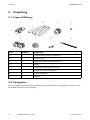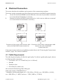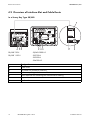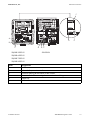
1
Plant Monitoring
485USPB-NR
Installation Manual
485USPB-NR-eng-IUS114912 | 98-0021412 | Version 1.2
CA
US
SMA America, LLC
Legal Restrictions
Copyright © 20.1.12 SMA America, LLC. All rights reserved.
No part of this document may be reproduced, stored in a retrieval system, or transmitted, in any form
or by any means, electronic, mechanical, photographic, magnetic or otherwise, without the prior
written permission of SMA America, LLC.
Neither SMA America, LLC nor SMA Solar Technology Canada Inc. makes representations, express
or implied, with respect to this documentation or any of the equipment and/or software it may
describe, including (with no limitation) any implied warranties of utility, merchantability, or fitness for
any particular purpose. All such warranties are expressly disclaimed. Neither SMA America, LLC nor
its distributors or dealers nor SMA Solar Technology Canada Inc. nor its distributors or dealers shall
be liable for any indirect, incidental, or consequential damages under any circumstances.
(The exclusion of implied warranties may not apply in all cases under some statutes, and thus the
above exclusion may not apply.)
Specifications are subject to change without notice. Every attempt has been made to make this
document complete, accurate and up-to-date. Readers are cautioned, however, that
SMA America, LLC and SMA Solar Technology Canada Inc. reserve the right to make changes
without notice and shall not be responsible for any damages, including indirect, incidental or
consequential damages, caused by reliance on the material presented, including, but not limited to,
omissions, typographical errors, arithmetical errors or listing errors in the content material.
All trademarks are recognized even if these are not marked separately. Missing designations do not
mean that a product or brand is not a registered trademark.
The Bluetooth® word mark and logos are registered trademarks owned by Bluetooth SIG, Inc. and
any use of such marks by SMA America, LLC and SMA Solar Technology Canada Inc. is under
license.
SMA America, LLC
3801 N. Havana Street
Denver, CO 80239 U.S.A.
SMA Solar Technology Canada Inc.
2425 Matheson Blvd. E
8th Floor
Mississauga, ON L4W 5K5
Canada
Installation Manual
485USPB-NR-eng-IUS114912
3
SMA America, LLC
Important Safety Instructions
IMPORTANT SAFETY INSTRUCTIONS
SAVE THESE INSTRUCTIONS
This manual contains important instructions for the following products:
• 485USPB-NR
This manual must be followed during installation and maintenance.
The product is designed and tested according to international safety requirements, but as with all
electrical and electronic equipment, certain precautions must be observed when installing and/or
operating the product. To reduce the risk of personal injury and to ensure the safe installation and
operation of the product, you must carefully read and follow all instructions, cautions and warnings
in this manual.
Warnings in this document
A warning describes a hazard to equipment or personnel. It calls attention to a procedure or practice,
which, if not correctly performed or adhered to, could result in damage to or destruction of part or all
of the SMA equipment and/or other equipment connected to the SMA equipment or personal injury.
Symbol
Description
DANGER indicates a hazardous situation which, if not avoided, will result in
death or serious injury.
WARNING indicates a hazardous situation which, if not avoided, could result
in death or serious injury.
CAUTION indicates a hazardous situation which, if not avoided, could result
in minor or moderate injury.
NOTICE is used to address practices not related to personal injury.
4
485USPB-NR-eng-IUS114912
Installation Manual
SMA America, LLC
Important Safety Instructions
Other Symbols in this document
In addition to the safety and hazard symbols described on the previous pages, the following symbols
are also used in this manual:
Symbol
Description
Indicates information that is important for a specific topic or objective, but is not
safety-relevant.
☐
Indicates a requirement for meeting a specific goal.
☑
Desired result
✖
A problem that could occur
Installation Manual
485USPB-NR-eng-IUS114912
5
General Warnings
SMA America, LLC
GENERAL WARNINGS
General Warnings
All electrical installations must be done in accordance with the local and National Electrical Code®
ANSI/NFPA 70 or the Canadian Electrical Code® CSA C22.1. This document does not and is not
intended to replace any local, state, provincial, federal or national laws, regulation or codes
applicable to the installation and use of the product, including without limitation applicable
electrical safety codes. All installations must conform with the laws, regulations, codes and
standards applicable in the jurisdiction of installation. SMA assumes no responsibility for the
compliance or noncompliance with such laws or codes in connection with the installation of the
product.
For all repair and maintenance, always return the unit to an authorized SMA Service Center.
Before installing or using the product, read all of the instructions, cautions, and warnings in this
manual.
Wiring of the product must be made by qualified personnel only.
6
485USPB-NR-eng-IUS114912
Installation Manual
SMA America, LLC
Table of Contents
Table of Contents
1
1.1
1.2
1.3
1.4
Information on this Manual. . . . . . . . . . . . . . . . . . . . . . . . .
Validity . . . . . . . . . . . . . . . . . . . . . . . . . . . . . . . . . . . . . . . . . . . .
Target Group . . . . . . . . . . . . . . . . . . . . . . . . . . . . . . . . . . . . . . .
Storage of the Manual . . . . . . . . . . . . . . . . . . . . . . . . . . . . . . . .
Nomenclature . . . . . . . . . . . . . . . . . . . . . . . . . . . . . . . . . . . . . . .
9
9
9
9
9
2
2.1
2.2
2.3
Safety . . . . . . . . . . . . . . . . . . . . . . . . . . . . . . . . . . . . . . . . . 10
Intended Use. . . . . . . . . . . . . . . . . . . . . . . . . . . . . . . . . . . . . . . 10
Skills of Skilled Workers . . . . . . . . . . . . . . . . . . . . . . . . . . . . . . 10
Safety Precautions. . . . . . . . . . . . . . . . . . . . . . . . . . . . . . . . . . . 11
3
3.1
3.2
Unpacking. . . . . . . . . . . . . . . . . . . . . . . . . . . . . . . . . . . . . . 12
Scope of Delivery . . . . . . . . . . . . . . . . . . . . . . . . . . . . . . . . . . . 12
Designation. . . . . . . . . . . . . . . . . . . . . . . . . . . . . . . . . . . . . . . . 12
4
4.1
4.2
4.3
4.4
Electrical Connection . . . . . . . . . . . . . . . . . . . . . . . . . . . . . 13
Cable Requirements . . . . . . . . . . . . . . . . . . . . . . . . . . . . . . . . . 13
Overview of Interface Slot and Cable Route . . . . . . . . . . . . . . 14
Installing the Communication Interface . . . . . . . . . . . . . . . . . . . 18
Connecting the Communication Interface. . . . . . . . . . . . . . . . . 18
4.4.1
Preparing the Enclosure Opening on the Inverter . . . . . . . . . . . . . . . . . . . . . 19
4.4.2
Routing the Cable in the Inverter. . . . . . . . . . . . . . . . . . . . . . . . . . . . . . . . . . 21
4.4.3
Connecting the Cable to the Communication Interface . . . . . . . . . . . . . . . . 23
4.5
Termination . . . . . . . . . . . . . . . . . . . . . . . . . . . . . . . . . . . . . . . . 24
5
5.1
5.2
Decommissioning . . . . . . . . . . . . . . . . . . . . . . . . . . . . . . . . 25
Disassembly . . . . . . . . . . . . . . . . . . . . . . . . . . . . . . . . . . . . . . . 25
Disposal . . . . . . . . . . . . . . . . . . . . . . . . . . . . . . . . . . . . . . . . . . 25
6
Compliance Information . . . . . . . . . . . . . . . . . . . . . . . . . . 26
Installation Manual
485USPB-NR-eng-IUS114912
7
Table of Contents
SMA America, LLC
7
Contact . . . . . . . . . . . . . . . . . . . . . . . . . . . . . . . . . . . . . . . . 27
8
485USPB-NR-eng-IUS114912
Installation Manual
SMA America, LLC
1
Information on this Manual
Information on this Manual
1.1 Validity
This manual applies to the communication interface 485USPB-NR.
This manual does not cover any details concerning equipment connected to the 485USPB-NR.
Information concerning the connected equipment is available from the manufacturer of the equipment.
1.2 Target Group
This manual is intended for skilled workers. Only skilled workers are allowed to perform the tasks set
forth in this manual (see Section 2.2 "Skills of Skilled Workers", page 10).
1.3 Storage of the Manual
Keep this manual in a convenient place for future reference.
1.4 Nomenclature
In this manual, SMA America Production, LLC and SMA Solar Technology Canada Inc. are
hereinafter referred to as SMA.
Installation Manual
485USPB-NR-eng-IUS114912
9
SMA America, LLC
Safety
2
Safety
2.1 Intended Use
The communication interface serves to establish cable-connected RS485 communication.
The communication interface may only be used with the following types of inverter.
• SB/WB 700-U
• SB/WB 5000-US
• SB/WB 1100-U
• SB 6000-U
• SWR 1800-U
• SB/WB 6000-US
• SWR 2100-U
• SB/WB 7000-US
• SWR 2500-U
• SB/WB 8000-US
• SB/WB 3000-US
• SB 8000TL-US
• SB 3300-U
• SB 9000TL-US
• SB 3800-U
• SB 10000TL-US
• SB 4000-US
The communication interface (485USPB-NR) complies with the following standards:
• FCC Part 15
The communication interface is provided as a retrofit kit or preinstalled in the inverter.
2.2 Skills of Skilled Workers
The tasks described in this manual are intended for skilled workers only. Skilled workers must have the
following skills:
• Training in how to deal with the dangers and risks associated with installing and using electrical
devices and plants
• Training in the installation and commissioning of electrical devices and plants
• Knowledge of all applicable standards and guidelines
• Knowledge of and adherence to this manual and all safety precautions
10
485USPB-NR-eng-IUS114912
Installation Manual
SMA America, LLC
Safety
2.3 Safety Precautions
Electric Shock
High voltages that can result in electric shocks are present in the conductive component parts of the
inverter.
• Prior to performing any work on the inverter, disconnect the inverter on the AC and DC sides
(see inverter installation manual).
Electrostatic Discharge
By touching electronic component parts, you can cause damage to or destroy the inverter through
electrostatic discharge (ESD).
• Ground yourself before touching any component parts.
Installation Manual
485USPB-NR-eng-IUS114912
11
SMA America, LLC
Unpacking
3
Unpacking
3.1 Scope of Delivery
A
B
E
F
C
G
Item
Quantity
Designation
A
1
Communication interface: 485PB-G3
B
2
Insulating hose
C
1
Cable gland (with double seal insert)
D
1
Jumper
E
2
Cable gland (with single seal insert)
F
2
Counter nut for the cable gland
G
1
Push-on receptacle
H
1
Cable tie
D
H
3.2 Designation
You can identify the communication interface by the type label. The type label is located on one of
the female connectors of the assembly.
12
485USPB-NR-eng-IUS114912
Installation Manual
SMA America, LLC
4
Electrical Connection
Electrical Connection
This section describes the installation and connection of the communication interface.
The inverter can be connected at one of the following two positions on the RS485 communication bus:
A
B
At one of the ends of the RS485 communication bus. In this case only one cable is connected
to a screw terminal. Termination is necessary.
Between the ends of the RS485 communication bus. In this case two cables are connected
to a screw terminal. No termination is necessary.
Connection of the inverter communication cable Connection of the inverter communication cable
at the end of the RS485 communication bus.
between the ends of the RS485
communication bus.
If the communication interface is preinstalled, proceed to Section 4.4 "Connecting the Communication
Interface", page 18 to continue installation.
4.1 Cable Requirements
The cable length and quality will affect the signal quality. To achieve a good quality signal, observe
the following cable requirements:
• Cross-section: min. 2 x 2 x AWG 24 (2 x 2 x 0.20 mm²)
• Shielded
• Twisted pair lines
• UV-resistant (for outdoor use)
We recommend the following SMA cable types:
SMA order number: COMCAB-OUTxxx*
*Available in the following lengths: xxx = 100 (100 m / 328 ft.); xxx = 200 (200 m / 656 ft.);
xxx = 500 (500 m / 1 640 ft.) and xxx = 1 000 (1 000 m / 3 280 ft.)
Installation Manual
485USPB-NR-eng-IUS114912
13
SMA America, LLC
Electrical Connection
4.2 Overview of Interface Slot and Cable Route
In a Sunny Boy Type SB/WB
SB/WB 700-U
SB/WB 3000-US
SB/WB 1100-U
SB 3300-U
SB 3800-U
SB 4000-US
Item
A
B
C
D
E
F
14
Designation
Cable route
Pin header for protective conductor
Enclosure opening at the bottom of the inverter
Screw terminals for connecting the communication cabling
Jumper slot
Interface slot
485USPB-NR-eng-IUS114912
Installation Manual
SMA America, LLC
Electrical Connection
F
E-Total 124.4kWh
h-Total
512h
S2
A
23 57
S1
B
A
B
C
B
A
SMC60-AST
C
B
A
277 V
V
V
0V
240
2 3 5 7
Potter & Brumfield
Potter & Brumfield
VN30.15/00858
Potter & Brumfield
A
208
V
V
0V
240
277 V
A B + -
208
2 3 5 7
D
VN30.15/00858
+
+
+
-
-
-
N
L2
L1
not
used
240 Vac:
N
L2
L1
not
used
277 Vac:
not
used
N
L1
not
used
208 Vac:
C
A
SB/WB 5000-US
E
86-0033
+
B
B C
SB 6000-U
SB/WB 6000-US
SB/WB 7000-US
SB/WB 8000-US
Item
A
B
C
D
E
F
Installation Manual
Designation
Cable route
Pin header for protective conductor
Enclosure opening at the bottom of the inverter
Screw terminals for connecting the communication cabling
Jumper slot
Interface slot
485USPB-NR-eng-IUS114912
15
SMA America, LLC
Electrical Connection
SB 8000TL-US
SB 9000TL-US
SB 10000TL-US
Item
A
B
C
D
E
F
16
Designation
Cable route
Pin header for protective conductor
Enclosure opening at the bottom of the inverter
Screw terminals for connecting the communication cabling
Jumper slot
Interface slot
485USPB-NR-eng-IUS114912
Installation Manual
SMA America, LLC
Electrical Connection
In a Sunny Boy Type SWR
A
D
C
B
A
SMA
SWR-SRR
VX.xx
C
SMA
SWR-BFR
VX.xx
B
ENS1
150 V
200 V
ENS2
L1 N PE
DC+
DC-
E FG
SWR 1800-U
SWR 2100-U
SWR 2500-U
Item
A
B
C
D
E
F
G
Installation Manual
Designation
Interface slot
Resistors (SWR inverters only)
Jumper slot
Screw terminals for connecting the communication cabling
Cable route
Enclosure openings at the bottom of the inverter
Pin header for protective conductor
485USPB-NR-eng-IUS114912
17
SMA America, LLC
Electrical Connection
4.3 Installing the Communication Interface
In SWR-type inverters it is possible that the interface slot is occupied by the display.
You can install either a display, or a communication interface.
To install the communication interface proceed as follows:
1.
Electric Shock
High voltages that can result in electric shocks are present in the conductive component parts
of the inverter.
• Prior to performing any work on the inverter, disconnect the inverter on the AC and DC
sides (see inverter installation manual).
• Open the inverter as described in the installation manual of the inverter.
2. Prior to installing the communication interface in
SWR-type inverters, remove the resistors marked
with a black ring with the aid of diagonal cutting
pliers.
C
B
A
only SWR
1 2 3 4 5 6 7 8 910
3. Plug the communication interface (A) flush-left on
the interface slot.
☑ The communication interface is now installed.
A
4.4 Connecting the Communication Interface
Electric Shock
High voltages that can result in electric shocks are present in the conductive component parts of the
inverter.
• Prior to performing any work on the inverter, disconnect the inverter on the AC and DC sides
(see inverter installation manual).
18
485USPB-NR-eng-IUS114912
Installation Manual
SMA America, LLC
Electrical Connection
4.4.1 Preparing the Enclosure Opening on the Inverter
Risk of damage to the inverter due to ingress of liquids.
• For the purpose of inserting the conduits into the enclosure, use only UL-certified rainproof
sleeves or waterproof sleeves that fulfill UL 514B.
In the following description we distinguish between inverter types with two or one enclosure openings.
Inverter Types with Two Enclosure Openings
1. Unscrew or push out the filler-plugs according to
the number of cables which are to be fed through
on the bottom side of the inverter.
2. Prepare the enclosure opening:
Enclosure opening with cable gland
Enclosure opening with conduit
• Insert cable glands with single seal insert • Insert conduits into the openings
in the appropriate openings on the
provided.
inverter.
• Screw to the inner side of the enclosure
using counter nuts.
☑ Preparation of the enclosure opening on the inverter is now complete.
Installation Manual
485USPB-NR-eng-IUS114912
19
Electrical Connection
SMA America, LLC
Inverter Types with One Enclosure Opening
1. Unscrew or push out the filler-plug from the hole on
the bottom side of the inverter.
2. Prepare the enclosure opening:
Enclosure opening with cable gland
Enclosure opening with conduit
• Insert cable gland with double seal insert • Insert conduit into the opening provided.
in the appropriate opening on the
inverter.
• Screw to the inner side of the enclosure
using counter nuts.
• Unscrew the swivel nut of the cable
gland. Press the seal insert out.
• Use a screwdriver to pierce the seal insert
according to the number of cables which
are to be fed through.
☑ Preparation of the enclosure opening on the inverter is now complete.
20
485USPB-NR-eng-IUS114912
Installation Manual
SMA America, LLC
Electrical Connection
4.4.2 Routing the Cable in the Inverter
Risk of electric shock due to incorrect installation of the communication cable.
Risk of death or serious injury due to contact with the communication cable.
If the communication cable is routed together with conductive cables, lethal voltages may be
induced.
• Always route the communication cables separately from the conductive cables.
Requirements:
☐ The swivel nut of the cable gland has been unscrewed.
1. Lead the cable into the enclosure through the swivel nut and the seal insert or through the
conduit. In doing so, lead the cable into the enclosure along the described cable route
(see Section 4.2 "Overview of Interface Slot and Cable Route", page 14) until it reaches the
terminals.
2. Strip the cable sheath to the length of the cable
route (C).
3. Cut back unneeded insulated conductors to the
length of the cable sheath (A).
A
4. Cut and twist the cable shield (B) to the length
needed to reach the protective conductor pin
header in the inverter.
B
C
D
5. Connect the push-on receptacle with the cable
shield.
6. Connect the push-on receptacle to the protective conductor pin header.
7. Strip 1⁄4 in. off the conductor insulation (D).
Installation Manual
485USPB-NR-eng-IUS114912
21
Electrical Connection
SMA America, LLC
8.
Risk of electric shock due to incorrect insulation of the communication cable.
Risk of death or serious injuries.
In case of incorrect insulation, high voltages outside of the inverter on the communication cable
are possible.
• Pull the insulating hose (A) over the insulated
conductors. In doing so the insulating hose
must completely cover the insulated
conductors inside the enclosure.
• If necessary, cut the insulating hose to the
required length.
9. Lead the insulated conductors with insulating hose (A) to the screw terminals in line with the
cable route (see Section 4.2 "Overview of Interface Slot and Cable Route", page 14).
10. Tighten the swivel nut of the cable gland to secure the cable.
☑ The routing of the cable in the inverter is now complete.
22
485USPB-NR-eng-IUS114912
Installation Manual
SMA America, LLC
Electrical Connection
4.4.3 Connecting the Cable to the Communication Interface
Requirements:
☐ The RS485 bus nodes are identically interconnected.
See the RS485 cabling plan poster for the terminal assignment, wiring, and termination of
an RS485 communication bus.
For the inverters described in this document use terminals 2, 5, and 7 of the screw terminal.
1. Release screws 2, 5, and 7 of the screw terminal
underneath the communication interface.
2 3 5 7
2. Connect the stripped insulated conductors to the
screw terminal.
3. Tighten screws 2, 5, and 7.
1 2 3 4 5 6 7 8 9 10
4. Pull the cable to check that it is securely in place.
5. Note the color of the insulated conductors:
Signal
GND
Data+
Data‒
485USPB-NR
5
2
7
Insulated conductor color
RS485 bus
5
2
7
6. Set the termination if necessary (see 4.5 "Termination", page 24).
7.
Close the inverter as described in the inverter manual.
☑ The communication interface is now connected.
Installation Manual
485USPB-NR-eng-IUS114912
23
SMA America, LLC
Electrical Connection
4.5 Termination
You only need to set the termination if the inverter is located at one end of the RS485 communication
bus. Termination is effected via a jumper at the jumper slot.
Refer to the RS485 cabling plan poster for the termination of an RS485 communication bus.
Carry out the following steps to terminate the RS485 communication bus:
Electric Shock
High voltages that can result in electric shocks are present in the conductive component parts of the
inverter.
• Prior to performing any work on the inverter, disconnect the inverter on the AC and DC sides
(see inverter installation manual).
1. Plug the jumper into jumper slot A in the inverter.
2. Close the inverter as described in the inverter
manual.
222 333 555 777
☑ The RS485 communication bus is now
terminated.
1 2 3 4 5 6 7 8 9 10
24
485USPB-NR-eng-IUS114912
Installation Manual
SMA America, LLC
5
Decommissioning
Decommissioning
5.1 Disassembly
1.
Electric Shock
High voltages that can result in electric shocks are present in the conductive component parts
of the inverter.
• Prior to performing any work on the inverter, disconnect the inverter on the AC and DC
sides (see inverter installation manual).
• Open the inverter as described in the installation manual of the inverter.
2. Remove the communication interface from the interface slot.
3. Release the screws of the screw terminal (counterclockwise), and remove conductors.
4. Remove the jumper, if applicable.
5. If necessary, remove cable ties.
6. Remove the push-on receptacle from the protective conductor pin header.
7. Remove insulating hose.
8. Loosen the nut of the cable gland (counterclockwise).
9. Pull the cable out of the device.
10. Remove the cable gland or conduit from the enclosure.
11. Close enclosure openings at the bottom of the inverter with filler-plugs.
12. Close the inverter as described in the inverter manual.
☑ The communication interface has been decommissioned.
5.2 Disposal
• Observe the disposal regulations for electronic waste that apply at the installation site when
disposing of the communication interface.
• To dispose of the communication interface, return the communication interface to SMA at your
own cost with the information "FOR DISPOSAL".
Installation Manual
485USPB-NR-eng-IUS114912
25
Compliance Information
6
SMA America, LLC
Compliance Information
FCC Compliance
This device complies with Part 15 of the FCC Rules. Operation is subject to the following conditions:
1. This device may not cause harmful interference, and
2. This device must accept any interference received, including interference that may cause
undesired operation.
NOTE: This equipment has been tested and found to comply with the limits for a Class A & B
digital device, pursuant to Part 15 of the FCC Rules. These limits are designed to provide reasonable
protection against harmful interference in a residential installation. This equipment generates, uses,
and can radiate radio frequency energy and if not installed and used in accordance with the
instructions, may cause harmful interference to radio communications. However, there is no guarantee
that interference will not occur in a particular installation. If this equipment does cause harmful
interference to radio or television reception, which can be determined by turning the equipment off
and on, the user is encouraged to try to correct the interference by one or more of the following
measures:
• Reorient or relocate the receiving antenna.
• Increase the separation between the equipment and the receiver.
• Connect the equipment into an outlet on a circuit different from that to which the receiver is
connected.
• Consult the dealer or an experienced radio/TV technician for help.
The user is cautioned that changes or modifications not expressly approved by
SMA America, Inc. could void the user’s authority to operate this equipment.
IC Compliance
This device complies with Industry of Canada licence-exempt RSS standard(s). Operation is subject
to the following two conditions:
• This device may not cause interference, and
• This device must accept any interference, including interferences that may cause undesired
operation of the device.
26
485USPB-NR-eng-IUS114912
Installation Manual
SMA America, LLC
7
Contact
Contact
If you have technical problems concerning our products, contact the SMA Serviceline. We require the
following information in order to provide you with the necessary assistance:
• Type of inverter
• Type and number of modules connected
• Communication method
• Sunny Boy failure or warning number
• Display message of the Sunny Boy
SMA Solar Technology America, LLC
6020 West Oaks Blvd, Ste 300
Rocklin, CA 95765
Tel. +1 916 625 0870
Tel. +1 877-MY SMA TECH
Tel. +1 877 697 6283 (Toll free, available for USA, Canada and Puerto Rico)
Fax +1 916 625 0871
[email protected]
www.SMA-America.com
SMA Solar Technology Canada Inc.
2425 Matheson Blvd E , 8th Floor
Mississauga, ON L4W 5K5 , Canada
Tel. +1 877 506 1756 (Toll free, available for Canada)
[email protected]
www.SMA-Canada.ca
Installation Manual
485USPB-NR-eng-IUS114912
27
4."4PMBS5FDIOPMPHZ
XXX4."4PMBSDPN
4.""NFSJDB--$
XXX4.""NFSJDBDPN