1
Accessory for
SUNNY BOY 2000HF-US
SUNNY BOY 2500HF-US
SUNNY BOY 3000HF-US
RS485-Quick Module
Installation Guide
RS485-QM-IA-eng-IUS111610 | IMUS-485QMODULE | Version 1.0
CA
US
YOUR ^DDISTRIBUTOR
SOLIGENT
800-967-6917
www.soligent.net
SMA America, LLC
Legal Restrictions
Copyright © 2011 SMA America, LLC. All rights reserved.
No part of this document may be reproduced, stored in a retrieval system, or transmitted, in any form
or by any means, electronic, mechanical, photographic, magnetic or otherwise, without the prior
written permission of SMA America, LLC.
Neither SMA America, LLC nor SMA Solar Technology Canada Inc. makes no representations,
express or implied, with respect to this documentation or any of the equipment and/or software it may
describe, including (with no limitation) any implied warranties of utility, merchantability, or fitness for
any particular purpose. All such warranties are expressly disclaimed. Neither SMA America, LLC nor
its distributors or dealers nor SMA Solar Technology Canada Inc. nor its distributors or dealers shall
be liable for any indirect, incidental, or consequential damages under any circumstances.
(The exclusion of implied warranties may not apply in all cases under some statutes, and thus the
above exclusion may not apply.)
Specifications are subject to change without notice. Every attempt has been made to make this
document complete, accurate and up-to-date. Readers are cautioned, however, that
SMA America, LLC and SMA Solar Technology Canada Inc. reserve the right to make changes
without notice and shall not be responsible for any damages, including indirect, incidental or
consequential damages, caused by reliance on the material presented, including, but not limited to,
omissions, typographical errors, arithmetical errors or listing errors in the content material.
All trademarks are recognized even if these are not marked separately. Missing designations do not
mean that a product or brand is not a registered trademark.
The Bluetooth® word mark and logos are registered trademarks owned by Bluetooth SIG, Inc. and
any use of such marks by SMA America, LLC and SMA Solar Technology Canada Inc. is under
license.
SMA America, LLC
3801 N. Havana Street
Denver, CO 80239 U.S.A.
SMA Solar Technology Canada Inc.
2425 Matheson Blvd
8th Floor
Mississauga, ON L4W 5K5
Canada
Installation Guide
RS485-QM-IA-eng-IUS111610
3
Important Safety Instructions
SMA America, LLC
IMPORTANT SAFETY INSTRUCTIONS
SAVE THESE INSTRUCTIONS
This manual contains important instructions for RS485-Quick Module
accessory, that must be followed during installation and maintenance of the inverter.
The RS485-Quick Module is designed and tested according to international safety requirements, but
as with all electrical and electronic equipment, certain precautions must be observed when installing
and/or operating the RS485-Quick Module. To reduce the risk of personal injury and to ensure the
safe installation and operation of the RS485-Quick Module, you must carefully read and follow all
instructions, cautions and warnings in this Installation Guide.
Warnings in this document
A warning describes a hazard to equipment or personnel. It calls attention to a procedure or practice,
which, if not correctly performed or adhered to, could result in damage to or destruction of part or all
of the SMA equipment and/or other equipment connected to the SMA equipment or personal injury.
DANGER
DANGER indicates a hazardous situation which, if not avoided, will result in death or
serious injury.
WARNING
WARNING indicates a hazardous situation which, if not avoided, could result in death or
serious injury.
CAUTION
CAUTION indicates a hazardous situation which, if not avoided, could result in minor or
moderate injury.
NOTICE
NOTICE is used to address practices not related to personal injury.
4
RS485-QM-IA-eng-IUS111610
Installation Guide
SMA America, LLC
Important Safety Instructions
Other Symbols in this document
In addition to the safety and hazard symbols described on the previous pages, the following symbol
is also used in this installation guide:
Information
This symbol accompanies notes that call attention to supplementary information that you should know and use to ensure optimal operation of the system.
General Warnings
General Warnings
All electrical installations must be done in accordance with the local and
National Electrical Code® ANSI/NFPA 70 or the Canadian Electrical Code®
CSA C22.1. This document does not and is not intended to replace any local, state,
provincial, federal or national laws, regulation or codes applicable to the installation and
use of the inverter, including without limitation applicable electrical safety codes. All
installations must conform with the laws, regulations, codes and standards applicable in
the jurisdiction of installation. SMA assumes no responsibility for the compliance or
noncompliance with such laws or codes in connection with the installation of the inverter.
For all repair and maintenance always return the unit to an authorized SMA Service
Center.
Before installing or using the RS485-Quick Module, read all of the instructions, cautions,
and warnings on the RS485-Quick Module in this installation guide.
Installation Guide
RS485-QM-IA-eng-IUS111610
5
General Warnings
6
RS485-QM-IA-eng-IUS111610
SMA America, LLC
Installation Guide
SMA America, LLC
Table of Contents
Table of Contents
1
1.1
1.2
1.3
1.4
Information on this Manual. . . . . . . . . . . . . . . . . . . . . . . . .
Validity . . . . . . . . . . . . . . . . . . . . . . . . . . . . . . . . . . . . . . . . . . . .
Target Group . . . . . . . . . . . . . . . . . . . . . . . . . . . . . . . . . . . . . . .
Additional Information . . . . . . . . . . . . . . . . . . . . . . . . . . . . . . . .
Nomenclature . . . . . . . . . . . . . . . . . . . . . . . . . . . . . . . . . . . . . . .
2
2.1
Safety . . . . . . . . . . . . . . . . . . . . . . . . . . . . . . . . . . . . . . . . . 10
Appropriate Usage . . . . . . . . . . . . . . . . . . . . . . . . . . . . . . . . . . 10
2.1.1
RS485 interface . . . . . . . . . . . . . . . . . . . . . . . . . . . . . . . . . . . . . . . . . . . . . . 10
2.1.2
Multi-function relay . . . . . . . . . . . . . . . . . . . . . . . . . . . . . . . . . . . . . . . . . . . . 10
2.2
Safety Instructions . . . . . . . . . . . . . . . . . . . . . . . . . . . . . . . . . . . 10
3
3.1
3.2
3.3
RS485-Quick Module. . . . . . . . . . . . . . . . . . . . . . . . . . . . . 11
Scope of Delivery . . . . . . . . . . . . . . . . . . . . . . . . . . . . . . . . . . . 11
Identification . . . . . . . . . . . . . . . . . . . . . . . . . . . . . . . . . . . . . . . 11
Interior View of the RS485 Quick Module . . . . . . . . . . . . . . . . 12
4
4.1
4.2
4.3
Preparations for the RS485 Quick Module . . . . . . . . . . . 13
Notes . . . . . . . . . . . . . . . . . . . . . . . . . . . . . . . . . . . . . . . . . . . . 13
Checking the Country Setting via the Rotary Switches . . . . . . . 13
Configuring the RS485 Quick Module. . . . . . . . . . . . . . . . . . . 14
4.3.1
Setting the language and installation country via the rotary switch . . . . . . . 14
4.3.2
Communication via Bluetooth . . . . . . . . . . . . . . . . . . . . . . . . . . . . . . . . . . . 16
4.4
Terminating the RS485 Bus. . . . . . . . . . . . . . . . . . . . . . . . . . . . 17
Installation Guide
RS485-QM-IA-eng-IUS111610
9
9
9
9
9
7
Table of Contents
SMA America, LLC
5
5.1
5.2
Assembly. . . . . . . . . . . . . . . . . . . . . . . . . . . . . . . . . . . . . . . 19
Open SMA DC-Disconnect. . . . . . . . . . . . . . . . . . . . . . . . . . . . 19
Connecting the RS485 Quick Module to the RS485 bus. . . . . 20
5.2.1
Cable Requirements . . . . . . . . . . . . . . . . . . . . . . . . . . . . . . . . . . . . . . . . . . . 20
5.3
5.4
5.6
5.7
Preparing the cable. . . . . . . . . . . . . . . . . . . . . . . . . . . . . . . . . . 20
Installing the Cable Pipe and Introducing the Cable into the
Inverter . . . . . . . . . . . . . . . . . . . . . . . . . . . . . . . . . . . . . . . . . . . 21
Replacing Standard Quick Modules with
RS485 Quick Modules . . . . . . . . . . . . . . . . . . . . . . . . . . . . . . . 22
Connecting the RS485 cable to the RS485 Quick Module . . . 23
Multi-function relay connection . . . . . . . . . . . . . . . . . . . . . . . . . 26
5.7.1
Connection Requirements . . . . . . . . . . . . . . . . . . . . . . . . . . . . . . . . . . . . . . . 26
5.8
Closing the SMA DC-Disconnect and
Commissioning the Inverter . . . . . . . . . . . . . . . . . . . . . . . . . . . . 28
6
6.1
6.2
Decommissioning and disposal . . . . . . . . . . . . . . . . . . . . 29
Decommissioning . . . . . . . . . . . . . . . . . . . . . . . . . . . . . . . . . . . 29
Disposal . . . . . . . . . . . . . . . . . . . . . . . . . . . . . . . . . . . . . . . . . . 29
7
Technical Data . . . . . . . . . . . . . . . . . . . . . . . . . . . . . . . . . . 30
8
Contact . . . . . . . . . . . . . . . . . . . . . . . . . . . . . . . . . . . . . . . . 31
8
RS485-QM-IA-eng-IUS111610
5.5
Installation Guide
SMA America, LLC
Information on this Manual
1 Information on this Manual
1.1 Validity
This guide applies to the RS485-Quick Module (485QMUS-10-NR) for the following SMA inverters:
• Sunny Boy 2000HF‑US (SB 2000HFUS-30)
• Sunny Boy 2500HF‑US (SB 2500HFUS-30)
• Sunny Boy 3000HF‑US (SB 3000HFUS-30)
1.2 Target Group
This manual is for qualified personnel. An qualified personnel has been sufficiently trained and has
proven capabilities and knowledge relating to the construction and operation of the device. An
qualified personnel is trained to deal with the dangers and hazards involved in installing electrical
systems.
1.3 Additional Information
Detailed information regarding installation, commissioning, maintenance and troubleshooting can be
found in the inverter installation guide.
Further information about SMA America, LLC equipment is available in the download section of the
www.SMA-America.com website. Among other things, the download area contains the following
items:
• Information on communication between devices by Bluetooth Wireless Technology by
SMA America, LLC in the "SMA Bluetooth Wireless Technology" technical description
• Information on detecting a free NetID in a Bluetooth network can be found in the
Sunny Explorer user manual.
1.4 Nomenclature
In this document, SMA America, LLC, and SMA Solar Technology Canada Inc. are hereinafter
referred to as SMA.
The "RS485-Quick Module 485QMUS-10-NR" is referred to in the following as
"RS485-Quick Module".
Installation Guide
RS485-QM-IA-eng-IUS111610
9
SMA America, LLC
Safety
2 Safety
2.1 Appropriate Usage
The RS485-Quick Module is provided as an upgrade kit or included in the scope of delivery of the
inverter.
The RS485-Quick Module is only suitable for use with SMA inverters of type Sunny Boy 2000HF-US
/ 2500HF-US / 3000HF-US. Please also observe the installation guide of the respective inverter.
2.1.1 RS485 interface
The RS485-Quick Module allows the setup of a cable-connected RS485 communication between the
aforementioned inverters.
2.1.2 Multi-function relay
The RS485-Quick Module has a multi-function relay that can serve as a fault signaling contact,
amongst other things. The inverter will trip the fault signaling contact as soon as an error occurs.
2.2 Safety Instructions
DANGER
Danger to life due to high voltages in the inverter.
• Only qualified personnel may perform work on the inverter.
• Disconnect the inverter on the AC and DC side as described in the inverter's
installation guide.
NOTICE
Electrostatic discharges can damage the RS485-Quick Module and the inverter.
• Ground yourself before touching a component part. Touch PE or a grounded object.
10
RS485-QM-IA-eng-IUS111610
Installation Guide
SMA America, LLC
RS485-Quick Module
3 RS485-Quick Module
The SMA inverters of the SB 2000 HF-US / 2500 HF-US / 3000 HF-US types are equipped with a
communication module (Quick Module) and a Bluetooth Wireless Technology interface by default.
You can retrofit the inverters with the RS485-Quick Module with an RS485 interface and multifunction
relay. For this, exchange the Quick Module delivered with the inverter for an RS485-Quick Module.
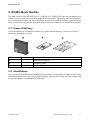
3.1 Scope of Delivery
Check the delivery for completeness and for any visible external damage. Contact your dealer if
anything is damaged or missing.
Object
A
B
C
Quantity
1
1
1
Description
RS485-Quick Module
Installation guide
RS485 cabling plan poster
3.2 Identification
You can identify the RS485-Quick Module by the type label. The type label is located on the outside
of RS485-Quick Module cover. The type label contains, amongst other things, the serial number and
the type designation of the RS485-Quick Module.
Installation Guide
RS485-QM-IA-eng-IUS111610
11
SMA America, LLC
RS485-Quick Module
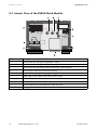
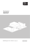
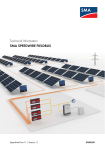
3.3 Interior View of the RS485-Quick Module
Object
A
B
C
D
E
F
G
H
I
K
12
Description
Rotary switch for setting the installation country
Rotary switch for setting the display language
Rotary switch for the configuration of Bluetooth communication
Multi-function relay and connection terminal
Jumper slot for setting the language to English
Strain relief for the cable of the multi-function relay
Slot for SD card
Strain relief for the RS485 cable
Shield clamps with 2 self-adhesive cooper foil strips
Spring-type terminal with connected resistor.
RS485-QM-IA-eng-IUS111610
Installation Guide
SMA America, LLC
Preparations for the RS485-Quick Module
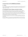
4 Preparations for the RS485-Quick Module
4.1 Notes
When the RS485-Quick Module is delivered, the resistor is located in the left spring-type terminal. If
you do not wish to connect the inverter to the end of the RS485 bus, you must remove the resistor, in
order to connect two cables.
4.2 Checking the Country Setting via the Rotary Switches
The factory default for the switches for setting the country configuration is at the 0/0 position.
If you install the RS485-Quick Module in an inverter, which has been in operation, and leave the
switches in the 0 / 0 position, then the country setting in the inverter remains unchanged.
You can change the country setting of the inverter using the rotary switches of the RS485-Quick
Module or a communication device. This overwrites the default network parameters. They cannot be
restored, and must be re-entered via a communication device.
The meaning of the positions of the rotary switches in the RS485-Quick Module are the same as in
the Standard Quick Module. Please read the inverter's installation guide to find the meaning of the
rotary switches.
The inverter changes the country settings and the language immediately after switching on the line
circuit breaker. If an un-programmed switch setting is selected, the inverter issues an error message.
Installation Guide
RS485-QM-IA-eng-IUS111610
13
Preparations for the RS485-Quick Module
SMA America, LLC
4.3 Configuring the RS485-Quick Module
4.3.1 Setting the language and installation country via the rotary
switch
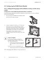
Configuration of the RS485-Quick Module Before Installation
If you have not yet installed the RS485-Quick Module, proceed as follows to set the installation
country and the language:
1. Flip up the flap of the RS485-Quick Module and lift
the cover until it snaps into place.
2. Using a screwdriver of width 1⁄8 in. (2.5 mm), set
the arrows on the two left-hand rotary switches
(A and B) to the desired position. The meaning of
the positions of the rotary switches in the RS485Quick Module are the same as in the Standard
Quick Module. Please read the inverter's
installation guide to find the meaning of the rotary
switches.
Jumper for English
You have the possibility to change the
language setting to English using a jumper
(e.g., during maintenance).
• Pull the jumper from the two right-hand
pins and attach it to the two left-hand
pins.
As soon as you have completed the work:
• Pull the jumper from the two left-hand pins and attach it to the two right-hand pins.
☑ The language and installation country have been set.
14
RS485-QM-IA-eng-IUS111610
Installation Guide
SMA America, LLC
Preparations for the RS485-Quick Module
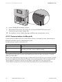
Configuration of the RS485-Quick Module After Installation
1. If the multi-function relay is already connected, switch off the multi-function relay power supply.
2. Open SMA DC-Disconnect (see section 5.1 „Open SMA DC-Disconnect.“ (page 19)).
3. Pull the RS485-Quick Module out to the stopper.
4. Flip up the flap of the RS485-Quick Module and lift
the cover until it snaps into place.
5. Set the installation country and display language (see section 4.3.1 „Setting the language and
installation country via the rotary switch“ (page 14)).
6. Set the NetID for Bluetooth communication unit (see section 4.3.2 „Communication via
Bluetooth“ (page 16)).
7. Close the cover of the RS485-Quick Module and
fold back the flap so that it snaps into place.
Installation Guide
RS485-QM-IA-eng-IUS111610
15
Preparations for the RS485-Quick Module
SMA America, LLC
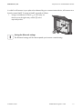
8. Push the RS485-Quick Module upwards.
9. Close SMA DC-Disconnect (see section 5.8 „Closing the SMA DC-Disconnect and
Commissioning the Inverter“ (page 28)).
☑ The installation country, display language, and Bluetooth communication are set.
4.3.2 Communication via Bluetooth
Communication via Bluetooth with a communication device is activated ex works. Networking via
Bluetooth with other inverters is deactivated ex works.
Possible settings using the rotary switch "C":
Switch position (NetID)
0
1
2 ... F
Setting
Off
Bluetooth communication with a communication device is possible. No
networking with other inverters (default setting)
Networking with other inverters
The NetID helps distinguish PV plants with SMA Bluetooth that are within a proximity of 1640 ft.
(500 m) of each other.
Detect a free NetID before commissioning your Bluetooth PV plant. This way you will make sure that
you will not register any other Bluetooth PV plant in your proximity. Refer to the user manual of the
"Sunny Explorer" software to discover how to detect a free NetID. The user manual of the
"Sunny Explorer" program can be found in the download section at www.SMA-America.com.
16
RS485-QM-IA-eng-IUS111610
Installation Guide
SMA America, LLC
Preparations for the RS485-Quick Module
In order for all inverters in your plant to be detected by your communication device, all inverters must
have the same NetID. To assign a NetID, proceed as follows:
1. Using a screwdriver of switch 1⁄8 in. (2.5 mm), set
the arrow on the right rotary switch (C) to the
required position.
Saving the Bluetooth settings
The Bluetooth settings will first be accepted upon inverter commissioning.
Installation Guide
RS485-QM-IA-eng-IUS111610
17
Preparations for the RS485-Quick Module
SMA America, LLC
4.4 Terminating the RS485 Bus
You must set the termination only on the inverter that is connected to the end of the RS485 bus. When
the RS485-Quick Module is delivered, the resistor for termination is located in the left spring-type
terminal. If the resistor (wire resistor: 120 Ohms) is no longer connected, proceed as described in this
chapter:
1. Flip up the flap of the RS485-Quick Module and lift
the cover until it snaps into place.
2. Open spring-type terminals 2 and 7 of the left-hand
connector.
3. Connect the resistor to spring-type terminals
2 and 7.
4. Close the spring-type terminals.
5. Close the cover of the RS485-Quick Module and
fold back the flap so that it snaps into place.
☑ The RS485 bus is terminated.
18
RS485-QM-IA-eng-IUS111610
Installation Guide
SMA America, LLC
Assembly
5 Assembly
5.1 Open SMA DC-Disconnect.
WARNING
High voltages in the inverter. Death or serious injuries.
• Before working on the SMA DC-Disconnect, disconnect the AC switch and make sure
it cannot be switched on.
• Disconnect the multi-function relay power supply.
• Set the DC disconnector of the SMA DC-Disconnect to the "Off" position.
• Wait 5 minutes before opening the cover of the SMA DC-Disconnect, until the
capacitors of the inverter are discharged.
1. Disconnect the AC switch and make sure it cannot be switched on.
2. Turn the DC disconnector to the "Off" position and
wait 5 minutes until the capacitors of the inverter
are discharged.
☑ The inverter is disconnected on the AC and DC
sides.
3. Loosen the screws on the enclosure of the SMA DCDisconnect (turn the screws in a counterclockwise
direction). Leave the screws and tab washers on the
cover.
4. Remove the cover of the SMA DC-Disconnect
towards the front.
5. Place the cover to one side.
☑ The SMA DC-Disconnect is open.
Installation Guide
RS485-QM-IA-eng-IUS111610
19
SMA America, LLC
Assembly
5.2 Connecting the RS485-Quick Module to the RS485 bus
5.2.1 Cable Requirements
The cable length and quality have an effect on the signal quality.
The cable must fulfill the following requirements to guarantee a good signal quality:
• Use cables of type 600V LVLE.
• Diameter of the cable: 15⁄64 in. (6 mm) to 17⁄64 in. (7 mm).
• Cross-section of the conductors: At least 2 x 2 x AWG 24 (2 x 2 x 0.22 mm²).
• Conductors must be made up of twisted wire pairs.
• The cable must be shielded and double insulated.
• For outdoor use only: the cable must be UV resistant.
You can order suitable cables from SMA.
Purchase order numbers:
• For outdoor use: COMCAB-OUTxxx*
*Available in the lengths xxx = 100 (100 m / 328 ft.); xxx = 200 (200 m / 656 ft.); xxx = 500 (500 m / 1 640 ft.) and
xxx = 1 000 (1 000 m / 3 280 ft.)
5.3 Preparing the cable
Length of the cable
When the cable has been connected, you must push the RS485-Quick Module approx.
8 in. (200 mm) upwards. Note that the cable has to be long enough to reach the end
position of the RS485-Quick Module.
Preparing the cable
Carry out the following steps outside the RS485-Quick Module, to ensure that no metal
residues of the shield or the cable fall into the RS485-Quick Module.
1. Ensure that the RS485 cable is long enough.
2. Shorten the cable sheath and cable shield by 1 1⁄2 in. (40 mm) (A).
20
RS485-QM-IA-eng-IUS111610
Installation Guide
SMA America, LLC
Assembly
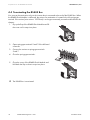
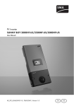
3. Shorten the cable sheath by 1⁄2 in. (15 mm) (B). Leave the cable shield on the cable.
4. Shorten the cable shield by 1⁄2 in. (15 mm) (B) and fold it back.
5. Cut off unused insulated conductors at the cable sheath to prevent a short-circuit. 3 conductors
are required. 2 conductors must be twisted.
6. Strip the conductors to a length of 1⁄4 in. (6 mm) (C).
7. Cover the shield with the delivered conductive
adhesive foil.
☑ The cable is prepared.
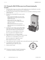
5.4 Installing the Cable Pipe and Introducing the Cable into the
Inverter
1. Push out the filler-plugs of an unused cable opening from the inside of the SMA DC-Disconnect
enclosure.
NOTICE
Damage to the SMA DC-Disconnect through enlargement of the cable pipe openings.
• Do not enlarge openings for the cable pipes. The openings are intended for the
installation of cable pipes with a size of up to 3⁄4 in. (19 mm).
2. Install the cable pipe on the free opening of the SMA DC-Disconnect. Use matching nuts on the
inside to screw the cable pipes to the the SMA DC-Disconnect.
3. If you want to install a fault sensor on the multi-function relay: Install the distribution box on the
cable pipe. The distribution box lets you lead the power supply of the multi-function relay and
the RS485 data cable to the DC-Disconnect.
4. Connect the cable pipe for the RS485 data cable and the cable pipe for the power supply of
the multi-function relay to the distribution box.
Installation Guide
RS485-QM-IA-eng-IUS111610
21
SMA America, LLC
Assembly
Properties of RS485 cables and the power supply of the multi-function relay
• Cable requirements for RS485 cables: see section 5.2.1 „Cable Requirements“
(page 20)
• Cable requirements for the power supply of the multi-function relay: see section
5.7.1 „Connection Requirements“ (page 26).
5. Lead the RS485 cable into the inverter through the cable pipe.
6. If you want to install fault sensor on the multi-function relay: lead the power supply of the multifunction relay into the inverter through the cable pipe.
☑ The cable pipes are installed and the cables are led into the inverter.
5.5 Replacing Standard Quick Modules with RS485-Quick Modules
1. Open SMA DC-Disconnect (see section 5.1 „Open SMA DC-Disconnect.“ (page 19)).
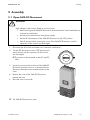
2. Pull the Quick Module downwards to the stopper.
3. Place your thumbs on the upper edge of the Quick
Module and carefully push the Quick Module
downwards using your thumbs. When the Quick
Module is at the end of the bracket, push the
bottom edge of the Quick Module forwards.
22
RS485-QM-IA-eng-IUS111610
Installation Guide
SMA America, LLC
Assembly
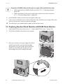
4. Plug the RS485-Quick Module into the designated holes on the bracket until it snaps into place.
5. Push the RS485-Quick Module carefully upwards.
6. Check that the RS485-Quick Module is securely in
place.
☑ The RS485-Quick Module is mounted. Should
you not have made these settings yet, you can
set the installation country, the display
language, and the Bluetooth communication
(see page 15).
7. Close the DC-Disconnect (see section 5.8 „Closing
the SMA DC-Disconnect and Commissioning the
Inverter“ (page 28)).
5.6 Connecting the RS485 cable to the RS485-Quick Module
In this guide it is assumed that the inverter is not connected to an end of the RS485 bus.
Should the inverter be connected to an end of the RS485 bus, perform the following steps
for one cable only.
If one cable is connected (inverter at the end of the RS485 bus) leave the resistor
connected to the spring-type terminal of the RS485-Quick Module.. If the resistor is not
correctly connected, see section 4.4 „Terminating the RS485 Bus“ (page 18).
1. Flip up the flap of the RS485-Quick Module and lift
the cover until it snaps into place.
2. When connecting 2 cables (inverter in the middle of
the RS485 bus), remove the resistor on the left
spring-type terminal.
Installation Guide
RS485-QM-IA-eng-IUS111610
23
SMA America, LLC
Assembly
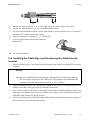
3. Slacken the strain relief screw in a counterclockwise
direction.
4. Remove the jumper.
5. Remove the filler-plug from the right-hand cable
entry.
6. If two cables are to be connected: remove the fillerplug from the left-hand cable entry.
7. Remove the cable support sleeve.
8. Insert the cable in the cable support sleeve.
9. Lead the end of the cable through the cable entry and
into the RS485-Quick Module.
10. Insert the cable support sleeve in the enclosure of the RS485-Quick Module.
11. Open the spring-type terminals.
24
RS485-QM-IA-eng-IUS111610
Installation Guide
SMA America, LLC
Assembly
12. Connect conductors to the connector terminals and note down the color of the wires:
Signal
GND
Data+
Data-
RS485-Quick Module Insulated conductor color
5
2
7
RS485 bus
5
2
7
13. Close the spring-type terminals.
14. Push the cable with the shield, stuck to the cable
with copper foil, into the shield terminal.
15. Attach the jumper.
16. Using a cross-head screwdriver, tighten the strain
relief screw in a clockwise direction with a torque of
13 1⁄4 in-lbs. (1.5 Nm).
17. Close the cover of the RS485-Quick Module and
fold back the flap so that it snaps into place.
18. Connect the other end of the cable to the RS485 bus. See the supplied RS485 cabling plan
poster for the connection layout and system wiring.
☑ The RS485-Quick Module is connected to the RS485 bus.
Installation Guide
RS485-QM-IA-eng-IUS111610
25
SMA America, LLC
Assembly
5.7 Multi-function relay connection
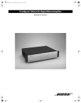
5.7.1 Connection Requirements
You have the possibility to use an external signal transmitter to display smooth operations as well as
errors.
You can switch the following voltages and currents.
Maximum voltage
15 V
30 V
AC source
DC source
Maximum current
1.0 A
1.0 A
Cable Requirements
• Use cables of type 600V LVLE.
• The cable type and cable-laying method must be appropriate to the application and location.
• The cable must be double-insulated.
Item
A
Description
External diameter
Value
15⁄ in. … 1⁄ in.
32
2
B
Cross-section of insulated conductor
(11.7 mm ... 12.5 mm)
AWG 20 … AWG 14
C
Maximum length of the insulated
conductor
Maximum strip insulation
D
26
RS485-QM-IA-eng-IUS111610
0.5 mm² ... 2.5 mm²
in. (15 mm)
1⁄
2
3⁄
8
in. (8 mm)
Installation Guide
SMA America, LLC
Assembly
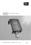
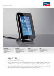
Connection plan for fault signaling contact
Installation Guide
RS485-QM-IA-eng-IUS111610
27
SMA America, LLC
Assembly
5.8 Closing the SMA DC-Disconnect and Commissioning the
Inverter
1. Check the cable routing to ensure that no cable impedes the cover seal and that the cover does
not apply pressure to the connections when it is screwed down.
2. Check all of the knockout fittings of the SMA DC-Disconnect and make sure that they provide a
weather-tight seal.
3. Place the cover of the SMA DC-Disconnect onto the
enclosure.
– Make sure that the handle in the cover of the
SMA DC-Disconnect snaps into the switch of the
SMA DC-Disconnect.
– Make sure that the upper edge of the
SMA DC-Disconnect is covered by the lower
edge of the inverter.
– Ensure that the two holes in the cover are
aligned exactly to the two threaded holes in the
enclosure.
4. Insert the two screws of the cover into the threaded
holes of the enclosure and hand tighten them. The
teeth of the tab washers must point downwards.
Be careful not to cross-thread any of the screws.
Do not use power tools to tighten the screws.
5. Ensure that the cover is correctly positioned.
6. Tighten the cover screws to a torque of 53 in-lbs. (6 Nm).
Be careful not to cross-thread any of the screws.
Do not use power tools to tighten the screws.
☑ The SMA DC-Disconnect is closed.
7. If the multi-function relay is connected: switch on the multi-function relay supply voltage.
8. Turn the DC disconnecting switch of the
SMA DC-Disconnect to the "On" position.
9. Switch-on the AC switch.
☑ The inverter is in operation. Successful commissioning
is indicated by a glowing or blinking green LED.
28
RS485-QM-IA-eng-IUS111610
Installation Guide
SMA America, LLC
Decommissioning and disposal
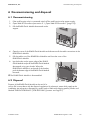
6 Decommissioning and disposal
6.1 Decommissioning
1. If the multi-function relay is connected: switch off the multi-function relay power supply.
2. Open SMA DC-Disconnect (see section 5.1 „Open SMA DC-Disconnect.“ (page 19)).
3. Pull the RS485-Quick Module downwards to the
stopper.
4. Open the cover of the RS485-Quick Module and disconnect all the cable connections in the
RS485-Quick Module.
5. Pull the cables out of the RS485-Quick Module and close the cover of the
RS485-Quick Module.
6. Lay the thumbs on the upper edge of the RS485Quick Module and push the RS485-Quick Module
downwards using your thumbs. When the
RS485-Quick Module is at the end of the bracket,
push the bottom edge of the RS485-Quick Module
forwards.
☑ The RS485-Quick Module is disassembled.
6.2 Disposal
Dispose of the RS485-Quick Module at the end of its
service life in accordance with the disposal regulations for electronic waste which apply at the
installation site at that time. Alternatively, send it back to SMA with shipping paid by sender and
labeled "ZUR ENTSORGUNG" ("FOR DISPOSAL") (contact: see Page 31).
Installation Guide
RS485-QM-IA-eng-IUS111610
29
SMA America, LLC
Technical Data
7 Technical Data
Communication
Communication Interfaces
Maximum RS485 range
RS485
3 935 ft. (1 200 m)
Environmental conditions in operation
Ambient temperature
Relative humidity*
− 13 °F … +131 °F
( − 25 °C … +60 °C)
5 % … 95 %
* Non-condensing
Ambient conditions during storage
Ambient temperature
− 40 °F … +185 °F
Relative humidity*
(–40 °C … +85 °C)
5 % … 95 %
* Non-condensing
General data
Width x height x depth
Weight
4 28⁄32 in. x 3 27⁄32 in. x 1 1⁄16 in.
(124 mm x 97.5 mm x 27 mm)
13⁄ lbs. (180 g)
32
Multi-function relay
Maximum AC voltage
Maximum DC voltage
Maximum AC current
Maximum DC current
30
RS485-QM-IA-eng-IUS111610
15 V
30 V
1.0 A
1.0 A
Installation Guide
SMA America, LLC
Contact
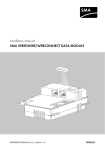
8 Contact
If you have technical problems concerning our products, contact the SMA Serviceline. We need the
following information in order to provide you with the necessary assistance:
• Inverter type
• Serial number of inverter
• Type and number of modules connected
• Event number or display of the inverter
• Type of communication, if applicable
• Type of external wiring of multi-functional relay
• Serial number of the RS485-Quick Module
SMA Solar Technology America, LLC
6020 West Oaks Blvd, Ste 300
Rocklin, CA 95765
Tel. +1 916 625 0870
Tel. +1 877-MY SMA TECH
Tel. +1 877 697 6283 (Toll free, available for USA, Canada, and Puerto Rico)
Fax +1 916 625 0871
[email protected]
www.SMA-America.com
SMA Solar Technology Canada Inc.
2425 Matheson Blvd, 8th Floor
Mississauga, ON L4W 5K5, Canada
Tel. +1 877 506 1756 (Toll free, available for Canada)
[email protected]
www.SMA-Canada.ca
Installation Guide
RS485-QM-IA-eng-IUS111610
31
4.""NFSJDB--$
XXX4.""NFSJDBDPN