1
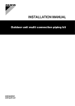
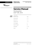
Step 2: Cut the insulation (5) along the slit (4). Fit the insulation
around the joint (6) and keep it in place with tape ( ) (7) without
leaving a gap between the two insulated parts.
Step 3: Seal the seam between the insulation and the field piping
insulation ( ) with tape ( ) (8).
Step 4: Cover the insulated parts completely with tape (
leaving any gaps (9).
■
All required tape is field supply.
■
In case of indoor installation, make sure that the tape
is of the fireproof type in order to comply with local
regulations.
Refer to the installation manual of the outdoor unit for
selection and restriction for the piping between outdoor
branches. Not observing restrictions on the interconnecting
piping may result in malfunctioning of the unit.
Pipe size selection and cutting position of joints.
Select the correct pipe size according with the tables below and cut
the joints and reducers on the correct places with a pipe cutter.
3 4 2
3
1
Main pipe
2
Outdoor unit multi connection
piping kit
3
Pipe between the outdoor unit
multi connection piping kit and
the outdoor unit
4
Connection inbetween
connection joints
3
CASE OF FRONT PIPING
1. EXTERIOR
) without
FOR CZ-48PJ2PQ
1 2
IN
1
2
3
4
5
6
7
8
1
9
10
7
5
1
11
2
1
12
13
1
2
3
4
5
6
7
Liquid pipe (field supply)
Gas pipe 1 (field supply)
Liquid side joint (1)
To indoor unit
Gas side joint (1)
Gas side reducer (1)
Liquid side reducer (1)
2. DIMENSIONS
8
9
10
11
12
13
Gas pipe (field supply)
Gas side joint (2)
Liquid side joint (2)
Gas pipe 2 (field supply)
Joint (angle of 90°) (field supply)
Gas pipe 3 (field supply)
FOR INSTALLATION
Table 11 Main pipe
■
Select the pipe size in function of the total capacity of the
outdoor unit.
detail B
Liquid
34 Hp
Ø34.9x1.21 (1/2H)
Ø19.1x0.80 (1/2H)
36~48 Hp
Ø41.3x1.43 (1/2H)
Ø19.1x0.80 (1/2H)
<143 mm
B
(a) OD x minimum wall thicknes (temper grade type)
Table 12 Pipe between the outdoor unit multi connection piping
kit and the outdoor unit
Pipe size
Outdoor unit
(a)
Gas
Liquid
10 Hp
Ø22.2x0.80 (1/2H)
Ø9.5x0.80 (O)
12~16 Hp
Ø28.6x0.99 (1/2H)
Ø12.7x0.80 (O)
■
Select the pipe size in function of the total capacity of the outdoor
units to be connected upstream.
A
284 mm (standard)
1
Gas pipe
2
Liquid pipe
3
Bottom frame
In case dimension A differs from 284 mm, adjust the field
supplied interconnection piping between the joint and the
outdoor unit.
Pipe size(a)
Total capacity
of upstream
outdoor units
Gas
Liquid
≤22 Hp
Ø28.6x0.99 (1/2H)
Ø15.9x0.99 (O)
24 Hp
Ø34.9x1.21 (1/2H)
Ø15.9x0.99 (O)
≥26 Hp
Ø34.9x1.21 (1/2H)
Ø19.1x0.80 (1/2H)
3. INSTALLATION
OF GAS AND LIQUID PIPES
Cutting the field supplied gas pipes
(a) OD x minimum wall thicknes (temper grade type)
Use the following table in case dimension A is 284 mm.
Cut the pipe with a pipe cutter
If dimension A differs from 284 mm, adjust the L dimensions of the
gas pipes 1, 2 and 3 accordingly.
2
Installation manual
7
B
Removing or attaching the front panel becomes impossible when
the distance between the bottom frame and the liquid pipe is more
than 143 mm.
(a) OD x minimum wall thicknes (temper grade type)
Table 13 Connection inbetween connection joints
B
171
Gas
1
2 3
Pipe size(a)
Total capacity
outdoor units
■
1
3
1
Joint or reducer
2
Cut in the center of the
connections.
3
Field pipe
For L dimension of gas pipe 3, dimension B of the field supplied
angled joint as in table 7 on page 3 has been taken into account. If
dimension B of the angled joint you use is different from that
dimension B, adjust the L dimension of gas pipe 3 accordingly.
CZ-32+48PJ2PQ
Outdoor unit multi connection piping kit
4PW21862-1A