1
Danaher Motion Kollmorgen
Wiring Instructions
WIRING INSTRUCTIONS
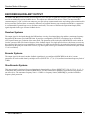
GROUNDING
System grounding is essential for proper performance of the drive system. A ground bus bar may be used as a single point
ground for the system. Safety grounding should be provided to all pieces of the system from a “star point." In addition to
the safety grounding, a high frequency ground must be provided that connects the back panel to the enclosure and,
ultimately, to earth ground. The objective is to provide an extremely low impedance path between the filters, drives,
power supplies, and earth ground. This high frequency ground is accomplished with the use of a flat braid or copper bus
bar. It is important not to rely on a standard wire for the high frequency ground. In general, a wire has an inductance of
8nH-per-inch, regardless of diameter. At higher frequencies, this unwanted inductance between grounds equates to
limited filter performance. When connecting high frequency grounds, use the shortest braid possible.
BONDING
The proper bonding of shielded cables is imperative for minimizing noise emissions and increasing immunity levels of
the drive system. Its effect is to reduce the impedance between the cable shield and the back panel. Danaher Motion
Kollmorgen recommends that all shielded cables be bonded to the back panel.
Power input wiring does not require shielding (screening) if the power is fed to the cabinet (enclosure) via metallized
conduit. If the metallized conduit is used with proper high frequency grounds, bonding technology, and recommended
wire routing, then power input wire shielding has no affect. In the event that metallized conduit is not implemented into
the system, shielded cable is required on the power input wires and proper bonding technologies should be implemented.
The motor and feedback cables should have the shield exposed as close to the drive as possible. This exposed shield is
bonded to the back panel using one of the two suggested methods described in this manual.
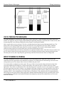
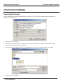
Non-insulated Cable Clamp
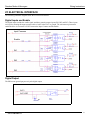
The following figures shows how cable bonding is implemented using non-insulated metallic cable clamps. The
first figure demonstrates clamping to the back panel in the vicinity of the drive. The second shows a technique for
bonding a terminal strip (for best results, it is recommended not to break the shielding of the cable).
From the drive
Terminal Strip
Bonded to Back
Plane
To Motor
Terminal Clamp and Power Block Clamp
SERVOSTAR PD
13