1
Danaher Motion Kollmorgen
System Operation
Analog Torque
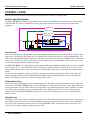
The SERVOSTAR PD can be configured to operate as an analog torque loop controller (OPMODE 3). In this case, the
current loop receives its input from the analog-to-digital (A/D) conversion system. After conversion, the input command
signal is processed through an algorithm which adjust the signal (ANOFF, ANDB, ANZERO), filters it (ANLPFHZ) and
then scales it (ISCALE), before developing the current command (ICMD). The current (or torque) command is then
checked against peak (IMAX, ILIM) and continuous (FoldBack features, ICONT) current clamp limits.
Sinusoidal commutation modulation is added to the command and then fed to the three-phase current loop regulator,
which calculates a current error. This error is then fed through a digital pole-placement compensation algorithm. The
output of the compensator is converted to a PWM signal and fed to the power transistor bridge. The power bridge uses
the high voltage DC Power Supply (typical 325 VDC bus) to supply the required current to the motor windings. The
actual motor current is updated and the process begins again.
Current Sampling
The current loop receives corrective feedback from the current sampling circuitry. The current sensors use closed-loop
hall sampling techniques in all units.
The current sample is used by the current loops to regulate the current in each of the three motor phases. Two phases (A
and C) of the current signal are sampled by the microprocessor at a 16kHz rate. The momentary A phase current and C
phase current can be monitored by examining the IA and IC variables, respectively. The microprocessor calculates the
equivalent absolute current, which can be monitored as I. This value can be averaged for 2, 4, 8, 16, 32, or 64 samples.
Foldback
The SERVOSTAR PD offers two types of FoldBack protection for both the motor and the drive. The drive’s
microprocessor monitors the current feedback signal and develops a RMS value of this signal for the purpose of
providing a value that represents the current in the motor. The system is similar to an “I-squared-T accumulator.
Drive FoldBack
This FoldBack algorithm monitors current feedback and, if the feedback exceeds the continuous current rating of the
drive/motor combination (ICONT), will decrease the system’s current to the ICONT level. For example, under a step
command input condition, the FoldBack algorithm will allow maximum peak current (IMAX) output from the drive for 2
seconds (or ½ second for Cx units). After two seconds, the drive enters “FoldBack mode” (FOLD=1) and begins an
exponentially FoldBack to the system’s continuous current. It takes approximately six seconds for the exponential decay
to drop from the system’s peak current to its continuous level.
For drive currents that exceed ICONT, but are below IMAX, the system period before FoldBack occurs is extended
beyond two seconds. Two seconds is the shortest time period that will elapse before the drive enters FoldBack and only
occurs when maximum peak current (IMAX) is drawn. This FoldBack feature is designed to protect the drive electronics,
not the motor. The Configurable Output, O1, (pin 12) can be configured to indicate a drive FoldBack condition.
Motor FoldBack
The FoldBack algorithm is designed to provide motor protection in cases where the drive’s continuous current rating is
above the motor’s continuous rating. This combination is often desired in applications where maximum peak motor
torques are required. However, the possibility exists that the drive could source current on a continuous basis indefinitely
to the motor and would force it beyond its thermal capability. Unlike the drive FoldBack, you have complete
configurability over this feature (MFOLD, MFOLDD, MFOLDDIS, MFOLDR, MFOLDT).
54
SERVOSTAR PD