1
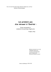
HHRP 11 and HHRP 17
Installation Manual
532028-2_A
Thank You!
Thank you for choosing Humminbird®, the #1 name in Fishfinders.
Humminbird® has built its reputation by designing and manufacturing topquality, thoroughly reliable marine equipment. Your Humminbird® accessory
is designed for trouble-free use in even the harshest marine environment.
In the unlikely event that your Humminbird® accessory does require repairs,
we offer an exclusive Service Policy - free of charge during the first year
after purchase, and available at a reasonable rate after the one-year period.
For complete details, see the separate warranty card included with your
accessory. We encourage you to read this manual carefully in order to get full
benefit from all the features and applications of your Humminbird® product.
Contact our Customer Resource Center at 1-800-633-1468 or visit our Web
site at humminbird.com.
W
ARNING!
Disassembly and repair of this electronic unit should only be performed
by authorized service personnel. Any modification of the serial number or
attempt to repair the original equipment or accessories by unauthorized
individuals will void the warranty.
W
ARNING!
This product contains chemicals known to the State of California to cause
cancer and/or reproductive harm.
N
OTE:
To purchase accessories for your control head, visit our Web site
at humminbird.com or contact our Customer Resource Center at
1-800-633-1468.
N
OTE:
Product specifications and features are subject to change without notice.
Environmental Compliance Statement: It is the intention of Johnson Outdoors
Marine Electronics, Inc. to be a responsible corporate citizen, operating in
compliance with known and applicable environmental regulations, and a good
neighbor in the communities where we make or sell our products.
WEEE Directive: EU Directive 2002/96/EC “Waste of Electrical and Electronic
Equipment Directive (WEEE)” impacts most distributors, sellers, and
manufacturers of consumer electronics in the European Union. The WEEE
Directive requires the producer of consumer electronics to take responsibility
for the management of waste from their products to achieve environmentally
responsible disposal during the product life cycle.
WEEE compliance may not be required in your location for electrical &
electronic equipment (EEE), nor may it be required for EEE designed and
intended as fixed or temporary installation in transportation vehicles such
as automobiles, aircraft, and boats. In some European Union member states,
these vehicles are considered outside of the scope of the Directive, and EEE
for those applications can be considered excluded from the WEEE Directive
requirement.
i
©
rs.
pry
nt.
rs,
ar
od.
ur
ull
t.
This symbol (WEEE wheelie bin) on product indicates the product must
not be disposed of with other household refuse. It must be disposed of
and collected for recycling and recovery of waste EEE. Johnson
Outdoors Marine Electronics, Inc. will mark all EEE products in
accordance with the WEEE Directive. It is our goal to comply in the collection,
treatment, recovery, and environmentally sound disposal of those products;
however, these requirements do vary within European Union member states.
For more information about where you should dispose of your waste equipment
for recycling and recovery and/or your European Union member state
requirements, please contact your dealer or distributor from which your
product was purchased.
eb
e
s
n
y
© 2012 Johnson Outdoors Marine Electronics, Inc. All rights reserved.
ii
Table of Contents
1.
1. General Information
1
2. Technical Specifications and Application
2
3. Description
3
3.1 General.. . . . . . . . . . . . . . . . . . . . . . . . . . . . . . . . . . . . . . . . . . . . . . . . . . . . . . . . . 3
3.2 Motor. . . . . . . . . . . . . . . . . . . . . . . . . . . . . . . . . . . . . . . . . . . . . . . . . . . . . . . . . . . 4
3.3 Pump . . . . . . . . . . . . . . . . . . . . . . . . . . . . . . . . . . . . . . . . . . . . . . . . . . . . . . . . . . 4
3.4 Valve Block and Valves. . . . . . . . . . . . . . . . . . . . . . . . . . . . . . . . . . . . . . . . . . . 5
4. Installation
6
4.1 Mechanical. . . . . . . . . . . . . . . . . . . . . . . . . . . . . . . . . . . . . . . . . . . . . . . . . . . . . . 6
4.2 Hydraulic. . . . . . . . . . . . . . . . . . . . . . . . . . . . . . . . . . . . . . . . . . . . . . . . . . . . . . . 6
4.3 Electrical . . . . . . . . . . . . . . . . . . . . . . . . . . . . . . . . . . . . . . . . . . . . . . . . . . . . . . . 7
5. Preparation and Testing
8
5.1 Hydraulic Filling and Testing. . . . . . . . . . . . . . . . . . . . . . . . . . . . . . . . . . . . . . 8
5.2 Testing. . . . . . . . . . . . . . . . . . . . . . . . . . . . . . . . . . . . . . . . . . . . . . . . . . . . . . . . . 8
6. Notes
9
7. Drawings
10
7.1 HHRP 11 and HHRP 17 — Assembly Schematic. . . . . . . . . . . . . . . . . . . . . . 10
7.2 HHRP 11 and HHRP 17 — System Connection Schematic. . . . . . . . . . . . . . 11
8. Contact Humminbird®
12
iii
A
a
ste
pu
po
th
sta
On
ar
th
wh
Mo
oil
lin
co
If a
in
lin
Th
to
Th
cy
HH
Mo
sid
ro
in
on
dr
are
un
is
cy
1. General Information
1
2
3
3
4
4
5
6
6
6
7
8
8
8
9
A hydraulic steering system consists of a hydraulic actuator (normally
a cylinder) and one or more steering wheel pumps (helm pumps). As the
steering wheel (helm pump) is turned in the port direction, hydraulic oil is
pumped into the port hydraulic steering line. This oil is directed into the
port side of the steering cylinder. As the cylinder moves to port, oil from
the starboard side of the cylinder returns to the helm pump through the
starboard hydraulic lines.
One end of the cylinder is fixed and the other end is connected to a tiller
arm, which is connected to a rudder shaft. With this connection to a tiller arm
the linear movement of the cylinder to port is changed to rotary movement,
which turns the rudder and steers the vessel to port.
Moving the steering wheel to starboard produces the same re-action with
oil being pumped out of the starboard line and returning through the port
line. If more the one helm pump is used, a return/fill line must be installed to
connect the cases of all the helm pumps together.
If an autopilot is to be installed, the hydraulic reversing pumpset is connected
in the same manner as a helm pump with a port, starboard and a return/fill
line.
The Humminbird® HHRP 11 and HHRP 17 are reversing pump units designed
to interface a hydraulic steering system with electric or autopilot control.
The output flow rate of the pumpset determines the speed of the steering
cylinder. The HHRP 11 pumpset outputs 1.0 cu in/sec or 16.4 cc’s/sec. The
HHRP 17 outputs 1.6 cu in/sec or 26.3 cc’s/sec.
Most steering cylinders are balanced, which means the volume of oil on both
sides of the cylinder is equal. A steering cylinder is balanced when the piston
rod of the cylinder protrudes from both ends. Some cylinders are unbalanced
in which the piston rod protrudes from one end only. These are common
on some in-board and out-board drives and are usually referred to as side
drives or simply unbalanced cylinders. These Humminbird® HHRP pumpsets
are capable of working with both balanced and unbalanced cylinders. When
unbalanced cylinders are used it is recommended that a vented header tank
is used to allow for the expansion and contraction from the unbalanced
cylinder.
10
10
11
12
1
General Information
2.Technical Specifications and Application
3.
MODEL
HHRP 11
HHRP 17
VOLTAGE
12 VDC
12 VDC
OUTPUT/SEC
1.0 cu in
1.6 cu in
4-6
5-8
10/4.5
10/4.5
AVERAGE AMP
WEIGHT (lbs/kgs)
3.
Th
co
ma
ma
The output flow rate of an electric pumpset determines the maximum speed
of the rudder. Under normal conditions a rudder speed of 10 to 16 seconds
will provide the best steering results for most autopilot systems. It is therefore
important to select the proper pumpset to optimize your autopilot operation.
First determine the volume of your steering cylinder. This is usually indicated
in the instruction manual of your steering system.
If you have to calculate the volume of your cylinder manually you can use the
following formula:
Volume = L(D2-d2)π÷4
where:
L = length of stroke of cylinder
D = internal diameter of cylinder
d = diameter of piston rod
π = 3.14 (Pi)
The rudder speed, hard over to hard over (HOH), is determined by dividing
the volume (cubic inches) of the cylinder by the output of the pumpset
(cubic inches per second). For example: a 15 cu in cylinder speed would be
approximately 14 seconds HOH using an HHRP 11 or approximately 9 seconds
using an HHRP 17.
Lin
to
lin
ou
Th
Specifications
2
3. Description
3.1 General
The Humminbird® HHRP 11 and HHRP 17 are complete pump assemblies each
consisting of a reversing gerotor gear pump, hydraulic lock valves, suction
make-up check valves, a valve housing manifold and an electric permanent
magnet motor.
FIGURE 3.1 HYDRAULIC SCHEMATIC
7
ed
ds
re
on.
8
9
5
6
3
ed
4
he
“A”
“B”
2
DC
MOTOR
ng
et
be
ds
1
Lines A and B are the output (port and starboard) lines, which are connected
to steering lines on the vessel. Line T is the tank suction make-up or return
line. These lines are clearly marked on the valve housing. Do not connect the
output lines to the tank (T) port.
The HHRP (Hydraulic Reversing Pumpset) operates as follows:
•
s the motor (1) rotates CCW, oil from the gear pump (2) is pumped
A
towards output “A”.
• This oil passes through the check valve (5) and goes to the line
output (7).
• The pressure at output “A” ensures the check valve (3) stays closed
and manually opens check valve (6).
• Opening check valve (6) allows the returning oil from the steering
cylinder to flow back to the pump.
3
Description
•
If the pressure at the pump suction “B” is less than the pressure in
the make-up line, oil from the make up line will pass by the check
valve (4). This prevents cavitation due to any air that may be in the
steering line.
• When the pump stops turning all spring-loaded check valves return
to the normally closed position.
•
When the motor (1) rotates (CW) the reverse movement of the oil
and valves takes place.
3.2 Motor
A list of features:
•
Ignition protected (UL 1500 and SAE-1171).
•
Ball bearing shaft supports both ends.
•
Extended motor shafting eliminating the pump/motor coupling.
•
Machined pilot bore ensuring aligned pump/motor adapter
mounting.
•
Cushioned foot mounts for quiet operation.
•
Opposite end shaft mount for tachometer/encoder.
3.3 Pump
A list of features:
•
The reversing gear pumps (HHRP’s) use gerotor style pump unit.
The gerotor gear was used because of its quiet operation and its
efficient pumping capabilities.
•
The gears are driven directly from the extended motor shaft which
eliminate the need for a pump/motor shaft coupling.
•
The shaft is supported by the motor ball bearing on one side and a
hard anodized aluminum end plate on the other side.
•
The gerotor pump is a two-piece gear assembly with an eccentric
ring. Proper clearances and alignments are maintained through
CNC precision machining.
•
Valve block sealing is accomplished using O-ring style seals.
•
The shaft seal is accomplished using a rubber shaft seal rated at
50 psi. This shaft seal is connected to the tank/return line pump
chamber. If this tank port is connected to a steering line or is
over pressurized, it may cause this seal to fail. See the installation
instructions for more details.
Description
4
3.
A
n
n
3.4 Valve Block and Valves
A list of features:
•
The valve block is an aluminum block, precision machined to house
the valves, direct the oil and serve as the endplate for the gear
pump. The pump end plate is referenced to the valve block with
locator pins to ensure the proper alignment.
•
The suction make-up valves are located between the return line
port and the pump output internal ports. These allow the pump
to “breathe” properly in the event of air from the steering lines
entering the pumpset.
•
The output check valves are part of what is called a lockvalve
assembly. The lockvalve assembly consists of two output check
valves and a lockvalve spool. In the non-running position the spring
operated check valves remain closed, isolating the pump from the
steering system. The spring action of the check valves holds the
lockvalve spool in the mid-closed position.
•
The end plate houses the pump shaft guide and aligns the pump.
.
h
a
h
p
n
5
Description
4. Installation
4.
4.1 Mechanical
The pumpset should be placed on a horizontal shelf or bracket with a solid
foundation. The pump can be bolted or screwed down with the motor foot
bracket. The foot bracket is fitted with anti-vibration mounts to maintain the
quiet operation of the pumpset. The pumpset should be close to and below
the steering lines for ease of connections and bleeding.
4.2 Hydraulic
Before connection to the hydraulic lines, ensure all hydraulic lines in the
steering system are clean and free of contaminating particles, which could
enter the pump and cause it to fail.
Most steering manufacturers have recommended hydraulic oils to be used
in their systems. The HHRP pumpsets are compatible with these oils. Most
manufacturers use an ISO #32 or ISO #10 type of oil.
Three hydraulic connections are required to the pumpset. Two lines connect
the pump (outputs A and B) to the main steering (port and starboard) lines.
It is not critical to identify which of the steering lines is port or starboard
as most new autopilots will determine the pump direction and program the
drive outputs to suit. For older autopilots the motor leads can be reversed to
change the pumps direction. The third line, which is the interconnect or fill
line, connects the pumpset to the header tank or helm pump case. This third
line is critical, as it provides make up oil and allows the pumpset to vent any
air, which may enter the pumpset from the steering lines. It is recommended
that flex hose be used for all three lines to prevent any pump noise from
being transmitted to the steering system. The port and starboard steering
lines should have a pressure rating of 1000 psi minimum; where the third fill/
interconnect line is a non-pressurized line. Shut-off or isolation valves for all
three lines are recommended. If the pumpset fails, the isolation valves can be
shut off and manual steering maintained.
The three hydraulic connections on the valve block are 9/16"-18 UNF (ORB
-06) threads and are fitted with adapter to 1/4" NPT (National Pipe Thread).
If installers prefer the adapters can be removed and connections can be
made directly to the valve block. When installing the hydraulic fitting in the
1/4" NPT connection a pipe thread sealant such as Teflon paste or tape must
be used.
C
AUTION!
It is important that the port or starboard line does not become crossed
with the fill/interconnect line as this could cause high pressure to be
introduced into the pumps tank cavity. In steering systems where the
fill/interconnect line is pressurized (e.g. - Hynautics or Teleflex) the
recommended operating pressure is approximately 20 to 25 psi. The
shaft seal on the HHRP pumpsets is rated at 50 psi and is well within
the pressure range of these steering systems. Over-pressurizing these
steering systems and causing a shaft seal failure will void the warranty
of the pumpset.
Installation
6
Th
co
pr
th
To
mo
dir
Us
Th
bu
lid
ot
he
ow
he
uld
4.3 Electrical
The motor is a permanent magnet style motor. There are two leads, which
connect to the autopilot pump driver junction box (processor). As mentioned
previously the direction of the pumpset can be reversed by simply reversing
the polarity of these two leads.
To test the operation of the HHRP pumpset, touch the two leads from the
motor to the supply voltage (12 VDC or 24 VDC) to jog the motor in one
direction and then reverse the leads to jog the pumpset in the other direction.
Use caution not to perform this operation where any combustible fumes exist.
The motors used on the HHRP 11 and HHRP 17 pumpsets are ignition protected,
built to conform to UL-1500 and SAE-1171 standards.
ed
ost
ct
s.
rd
he
to
fill
rd
ny
ed
om
ng
ll/
all
be
RB
d).
be
he
ust
e
7
Installation
5. Preparation and Testing
6.
5.1 Hydraulic Filling and Testing
When installing a pumpset it is recommended that the system be flushed
to ensure that the oil is clean and free of contamination through out the
hydraulic steering system.
After the hydraulic and electrical connection have been made, open all valves
if installed, and allow sufficient time for the pump and lines to fill with oil.
Operate the pumpset and note the HOH time. This time varies with the type
of steering system and autopilot used.
5.2 Testing
Set the autopilot to the manual mode and operate the pumpset to determine if
the port and starboard directions are correct. If the rudder goes the opposite
way, reverse the two electrical leads to the motor.
Most new autopilot systems will perform this test during their dockside
set-up procedures.
Preparation and Testing
8
6. Notes
ed
he
es
oil.
pe
e if
ite
de
9
Notes
7. Drawings
7.
7.1 HHRP 11 and HHRP 17
ASSEMBLY SCHEMATIC
4"
SIDE VIEW
8"
A
3.25"
T
TOP VIEW
4"
B
2.25"
Shipping weight: 10 lbs • Dimensions: 10" x 5" x 5"
Drawings
10
7.2 HHRP 11 and HHRP 17
SYSTEM CONNECTION SCHEMATIC
HELM
PUMP
STARBOARD LINE
STEERING
CYLINDER
PORT LINE
T
A
B
11
Drawings
Contact Humminbird®
Contact the Humminbird® Customer Resource Center
in any of the following ways:
By Telephone:
(Monday - Friday 8:00 a.m. to 4:30 p.m. Central Standard Time):
1-800-633-1468
By e-mail:
(typically we respond to your e-mail within three business days):
[email protected]
For direct shipping, our address is:
Humminbird
Service Department
678 Humminbird Lane
Eufaula, AL 36027 USA
Contact Humminbird®
12