1
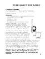
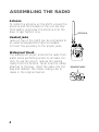
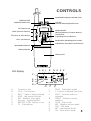
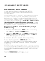
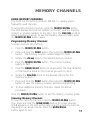
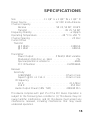
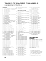
OPERATIONS MANUAL
TABLE OF CONTENTS
Parts Supplied . . . . . . . . . . . . . . . . . . . . . . . . . . . .2
Accessories . . . . . . . . . . . . . . . . . . . . . . . . . . . . . .3
Batteries . . . . . . . . . . . . . . . . . . . . . . . . . . . . . . . .3
Section 1: ASSEMBLING THE RADIO . . . . . . . . . . . . . . .4
Section 2: CONTROLS . . . . . . . . . . . . . . . . . . . . . . . . .5
Section 3: BASIC OPERATION . . . . . . . . . . . . . . . . . . . .6
Section 4: SCANNING FEATURES . . . . . . . . . . . . . . . . .9
Scanning All Channels . . . . . . . . . . . . . . . . . . . . . .9
Dual and Triple Watch Scanning . . . . . . . . . . . . . .10
Section 5: MEMORY CHANNELS . . . . . . . . . . . . . . . . .11
Section 6: MAINTENANCE AND WARRANTY
Maintenance . . . . . . . . . . . . . . . . . . . .
Service Policy . . . . . . . . . . . . . . . . . . . .
Warranty . . . . . . . . . . . . . . . . . . . . . . .
Customer Support . . . . . . . . . . . . . . . .
Specifications . . . . . . . . . . . . . . . . . . . .
Section 7: TABLE OF MARINE CHANNELS
.
.
.
.
.
.
.
.
.
.
.
.
.
.
.
.
.
.
.
.
.
.
.
.
.
.
.
.
.
.
.
.
.
.
.
.
.
.
.
.
.
.
.12
.12
.13
.14
.14
.15
. . . . . . . . . .16
PARTS SUPPLIED
Before using the VHF5, please ensure the following parts are
included in the box:
• VHF5 Radio and Battery Pack
• Antenna
• Waterproof Pouch
• Operations Manual
If any of these items are missing, call our Customer Support Hotline.
2
ASSEMBLING THE RADIO
OTHER ACCESSORIES
The following accessories are available from most
Humminbird dealers, or direct through Humminbird
Customer Support:
Accessory
• 12V Cigarette Lighter Adapter/Battery Eliminator
• Speaker/Microphone Headset
• Waterproof Pouch
• Bulkhead Mount
• NiCd Battery Pack and Battery Charger
Battery Installation and Removal.
The VHF5 (models A and C) uses 8 AA
Alkaline batteries to power the radio. These
batteries (not included) are installed in the
battery pack at the bottom of the radio.
To install new batteries, move the Battery
Release button up, and slide the battery
pack off as shown in the illustration. Using
your finger, disengage the snap lock feature
on the top of the battery pack, and gently
separate the battery pack into two halves.
Install four new batteries in each half of the
battery pack. Assure the positive and negative orientation of
the batteries match the engraving on the inside of the battery back. To reassemble the battery pack, first mate the
two halves together at the bottom and then snap shut.
Slide the battery pack onto the radio. When the battery is
low, a battery icon appears on the LCD. The battery pack
can be charged on or off the VHF5 unit.
Note: For longest battery life use only new Alkaline
batteries. Battery life varies greatly by brand and
length of time the radio is used for transmitting and
receiving.
3
ASSEMBLING THE RADIO
Antenna
To install the antenna on the VHF5, ensure the
antenna and the threads on the unit are free
from debris, and screw the antenna onto the
base. Finger tighten only.
Antenna
Headset Jacks
Jacks on top of the VHF5 can be connected to
an external speaker/microphone headset.
Connect this accessory to the proper jacks.
Waterproof Pouch
The waterproof pouch protects the radio from
water while permitting access to all radio controls. To use the pouch, remove the sealing
clamp from the bottom. Note how the clamp
attaches to the bag. Insert the radio into the
bag and reattach the clamp, taking care to
reseal in the original manner.
4
Headset jacks
CONTROLS
Speaker/Microphone Headset Jacks
PWR/VOLUME
(PWR/VOLUME Knob)
CHL/SQL
Channel Selector/Squelch Knob
16 (Channel 16)
MEMO/M.PRG
(Memory/Memory Program Button)
FUNC (Function Button)
LIGHT/LOCK
(Light/Keypad Lock Button)
PTT (Push to-Talk) Button
CALL (Call Button)
BAND/HI/LO (Band/High/low power)
SCAN/DUAL (Scan/Dual mode Button)
Speaker/Microphone
Battery Release
Battery Pack
L H J
LCD Display
C
R
N G E K
FUNC DUAL TRI SCAN WA L
A
B
D
M
CALL LOW
WX USA INT
O
A.
B.
C.
D.
E.
F.
G.
H.
Channel in Use
CALL - Call Function
BUSY - Signal is being received
LOW - Low power function
WA - Weather Alert signal
Key Icon - Keypad locked
BATTERY ICON - Battery is low
TX - Transmitting
F
MEMO
BUSY TX
P
J.
K.
L.
M.
N.
O.
P.
Q.
R.
Q
DUAL - Dual watch mode
L -Channel is deleted from scan
FUNC - Function button is
activated
MEMO - Memory channel
selection
SCAN - Scan mode
WX - Weather receive mode
USA - USA band
INT - International band
TRI - Triple watch mode
5
BASIC OPERATION
The MEMO/M.PRG, SCAN/DUAL, BAND/HI/LO, and LIGHT/LOCK
buttons are dual-function buttons. The primary function is printed
above, and secondary function is printed below.
TURNING THE UNIT ON/OFF
Rotate the PWR/VOLUME knob clockwise until it clicks to turn the
unit on. To turn the unit off, rotate the knob counter-clockwise until
it clicks.
SELECTING A BAND
Three bands are available on the VHF5 - USA, International and
Weather. The USA band are frequencies for use in US boundaries. The
International band are frequencies for use outside US boundaries. The
Weather band monitors NOAA/Canada weather broadcasts. To switch
between bands, press the BAND/HI/LO button until the desired band
is reached. The band in use is indicated on the LCD by USA, INT or
WX. When tuned to the WX band and the active weather channel for
your area, the VHF5 will sound NOAA Weather Alert tones as they
are received. Note: The VHF5 will sound NOAA Weather Alert
tones even when the volume is turned down. You must turn
volume up to hear specific weather alerts for your area.
SELECTING A CHANNEL
Select the appropriate band - USA, International or Weather. Once
the band is selected, rotate the CHL/SQL knob either clockwise or
counter-clockwise to scroll through the available channels. Note: Not
all channel numbers are available in all bands. Certain channels
are receive only, while others transmit and receive on different
frequencies (not duplex channels). Additionally, several channels broadcast on LOW power only. See Table of Marine
Channels for detail.
TRANSMITTING A CALL
The PTT (Push-To-Talk) button is located on the side of the VHF5.
Before transmitting, make sure the channel is not a “receive-only”
channel. To transmit a message press and hold the PTT button. Talk
clearly into the speaker/microphone area of the radio. When finished,
release the PTT button. During a transmission, TX appears on the
LCD. Note: while transmitting a message, the radio can not
receive a call.
6
BASIC OPERATION
ADJUSTING SQUELCH
Squelch is used to eliminate static and background noise and
allows for silent operation of the VHF5 until a transmission is
received. If the Squelch is too high, only the strongest transmissions are heard, and when too low, intermittent static and
noise are heard.
To adjust the squelch, press and hold the FUNC button then
turn the CHL/SQL knob until the background noise is quiet.
The LCD displays the squelch setting from 00 to 08.
HI/LO POWER
Press and hold the FUNC button then press the BAND/HI/LO
button to toggle between high and low power. High power is
5.0 watts, and low power is 1.0 watts. When the unit is
operating at low power, LOW appears on the LCD and disappears when operating at high power. Note: Some channels
are limited to LOW power output only.
CHANNEL 16
Channel 16 is the standard channel for placing a call or for an
emergency broadcast. The 16 button selects Channel 16
immediately. To exit, press the 16 button again. Channel 16 is
the same frequency on both the USA and International bands.
7
BASIC OPERATION
CALL BUTTON
The CALL button allows for quick access to a frequently
used channel referred to as the Call Channel. Once the CALL
button is pressed, CALL appears on the LCD. To exit, press
the CALL button again.
Programming the Call Channel
1. Press the CALL button. CALL appears in the LCD.
2.
Press and hold the FUNC button then press the CALL
button. The display will flash. Release all buttons.
3.
Rotate the CHL/SQL button to the desired call channel.
4.
Press and hold the FUNC button then press the CALL
button to store the Call Channel.
BACKLIGHT
To use the backlight, press the LIGHT/LOCK button.
The backlight stays illuminated for a few seconds.
KEY PAD LOCK
To active the keypad lock, press and hold the FUNC button
then press the LIGHT/LOCK button. The PTT, 16 and
LIGHT/LOCK buttons still operate while the keypad is locked.
To unlock the keypad, press and hold the FUNC button then
press the LIGHT/LOCK button. The key icon appears on the
LCD when the keypad is locked.
MONITOR
The monitor function allows faint signals on a channel to be
heard. To activate the monitor function, press and hold the
FUNC button to hear all traffic on the current channel.
Release the FUNC button when finished listening.
8
SCANNING FEATURES
SCANNING ALL CHANNELS
The VHF5 scans all channels in one of two modes: normal or
priority scan. You may program the VHF5 to scan in either mode.
In normal scanning, the VHF5 rapidly scans through channels,
either in the USA or International band. The VHF5 stops scanning
on busy channels and remains stopped several seconds after the
signal disappears allowing time to answer the call if necessary.
In priority scanning, the scanning operation is the same as
normal scanning except Channel 16 is constantly checked for
activity, allowing for much quicker response to Channel 16 traffic.
To scan channels, press and hold the SCAN/DUAL button for a
few seconds. The VHF5 begins scanning channels using the scan
method programmed in the radio. The word SCAN appears on
the LCD. To stop scanning, press the SCAN/DUAL button.
Programming for Normal or Priority scanning:
1. Turn the unit off. Press and hold the FUNC button while
turning the power on. The unit displays 02 or 03. Release
the FUNC button.
2. Press the FUNC button again. The radio displays n-sc
or p-sc.
3. Rotate the CHL/SQL knob to choose n-sc for normal scan,
or p-sc for priority scan.
4. Press the 16 button twice to store programming.
Deleting Channels from Scan
To delete a channel from scan, select the channel to be deleted.
Press the FUNC and SCAN/DUAL buttons at the same time.
L appears on the LCD, indicating the channel is locked out of
scan. This is useful for bypassing channels that are continuously
busy. To activate a deleted channel, select the channel to be
activated then press the FUNC and SCAN/DUAL buttons at
the same time.
9
SCANNING FEATURES
DUAL AND TRIPLE WATCH SCANNING
To scan selected channels, there are three options:
Dual Watch, Dual Watch with NOAA Weather Alert,
and Triple Watch.
In Dual Watch scanning, the VHF5 toggles between Channel
16 and the current channel. In Dual Watch with Weather
Alert scanning, the VHF5 toggles between Channel 16, the
current channel, and monitors the current weather channel
for a NOAA Weather Alert signal. Note: The VHF5 monitors
the last selected weather channel in this mode. In Triple
Watch scanning, the VHF5 toggles between Channel 16, the
Call Channel, and the current channel.
Programming for Dual, Dual with Weather, or Triple
Watch Scanning
1. Turn the unit off. Press the FUNC button while turning
the power on. Release the FUNC button.
2. Rotate the CHL/SQL knob until 02du (for Dual Watch),
03du (for Dual Watch with Weather Alert), or 03tr (for
Triple Watch) appears on the LCD.
3. Press the 16 button twice to store programming.
To scan channels, press the SCAN/DUAL button.
The VHF5 begins scanning channels using the scan method
programmed in the radio. The word DUAL or TRI appears
on the LCD.
The VHF5 rapidly scans through channels, and stops scanning
on busy channels. The VHF5 remains stopped several seconds
after the signal disappears allowing time to answer the call if
necessary.
Press the SCAN/DUAL button again to exit.
10
MEMORY CHANNELS
USING MEMORY CHANNELS
The VHF5 has 10 memory locations (00-09), to quickly access
frequently used channels.
To access the memory channels, press the MEMO/M.PRG button.
The LCD displays the channel number on the left, and the memory
location in smaller numbers to the right. Turn the CHL/SQL knob to
select a memory channel. To exit the memory channel mode, press
the MEMO/M.PRG button again.
Programming Memory Channels
To enter channels into memory:
1. Press the MEMO/M.PRG button.
2. Press and hold the FUNC button then press the MEMO/M.PRG
button. The memory location number begins to flash.
3. Rotate the chl/sql knob to the desired memory location.
4. Press the MEMO/M.PRG button. The channel number
begins to flash.
5. Press the BAND/HI/LO button to select either the USA, Weather,
or International band for the channel you wish to store.
6. Rotate the CHL/SQL knob to the desired channel for this
memory location.
7. Press and hold the FUNC button then press the MEMO/M.PRG
button to save the memory location and exit programming.
8. To store additional memory channels, repeat the above
procedure.
Press the MEMO/M.PRG button to exit the memory channel mode.
Scanning Memory Channels
To scan the memory channels, press the MEMO/M.PRG button,
then press and hold the SCAN/DUAL button for a few seconds.
SCAN appears on the LCD as the radio scans the memory channels,
stopping on an active channel. Press the SCAN/DUAL
button again to exit.
11
MAINTENANCE AND WARRANTY
MAINTENANCE
The VHF5 is designed to provide years of trouble free
operation with virtually no maintenance. Follow these
simple procedures to ensure the VHF5 continues to deliver
top performance.
While the VHF5 is generally water resistant, it is NOT waterproof. Avoid exposing the unit to water spray or rain.
Do not immerse the unit in water. Use the waterproof
pouch to protect the radio.
If the unit comes into contact with salt spray, simply wipe the
affected surfaces with a cloth dampened in fresh water. Do
not use a chemical glass cleaner on the lens. Chemicals in the
solution may cause cracking in the lens of the unit.
When cleaning the LCD protective lens, use a chamois and
non-abrasive, mild cleaner. Do not wipe while dirt or grease is
on the lens. Be careful to avoid scratching the lens.
Never leave the VHF5 in a closed car or trunk - the extremely
high temperatures generated in hot weather can damage
the electronics.
12
MAINTENANCE AND WARRANTY
SERVICE POLICY
This Service Policy is valid in the United States only. This
applies to Humminbird units returned to our factory in
Eufaula, Alabama, and is subject to change without
notice.
All repair work is performed by factory-trained technicians to
meet exacting factory specifications. Factory serviced units go
through the same rigorous testing and quality control inspection as new production units.
Even though you’ll probably never need to take advantage
of our incredible service guarantee, it’s good to know that
we back our units this well. We do it because you deserve
the best. We will make every effort to repair your unit within
three working days from the receipt of your unit. This does
not include shipping time to and from our factory. Units
received on Friday are usually shipped by Wednesday, units
received Monday are usually shipped by Thursday, etc.
We reserve the right to deem any product unserviceable
when replacement parts are no longer reasonably available
or impossible to obtain.
After the original warranty period, a standard flat rate service
charge will be assessed for each repair (physical damage and
missing parts are not included). Please call our Customer
Support Department to verify the service charge for your unit.
If shipping charges are not prepaid, the unit will be returned
C.O.D.
13
MAINTENANCE AND WARRANTY
HUMMINBIRD ONE YEAR FULL WARRANTY
First year repairs (from original date of purchase) on your VHF5 are
absolutely free. This does not include physical damage to the unit or
its accessory items. Any modification or attempt to repair the original
equipment or accessories by unauthorized individuals will void the
warranty. Return the warranty registration card and retain your bill
of sale for warranty verification. Accessories not manufactured under
the Humminbird trade name are not covered by our warranty. The
customer is responsible for shipping charges to Humminbird.
Humminbird will provide ground UPS or Parcel Post shipping back to
the customer free of charge. This warranty applies to the original
purchaser only.
This warranty is in lieu of all other warranties expressed or implied
and no representatives or persons are authorized to provide for
any other liability in connection with the sale of our products.
Humminbird reserves the right to perform modifications or improvements on its products without incurring the obligation to install the
changes on units previously manufactured, sold, delivered, or serviced.
THIS IS A FULL WARRANTY AS DEFINED BY THE FEDERAL WARRANTY
ACT, EFFECTIVE JULY 4, 1975.
CUSTOMER SUPPORT
If you have any questions, call our Humminbird Customer Support
Hotline: 1-334-687-0503
Throughout the U.S. and Canada, hours are Monday-Friday, 8:00 a.m.
to 5:00 p.m. Central time.
If you determine your unit needs factory service, please attach a
description of the problem and send it with the unit to the address
below. If you are including a check, please attach it to the unit.
14
Humminbird
Service Department
Three Humminbird Lane
Eufaula, AL 36027
SPECIFICATIONS
Size
. . . . . . . . . . . . . . . . .11 1/8" H x 2 3/4" W x 1 3/4" D
Power Source . . . . . . . . . . . . . . . . . . . .12 VDC 8 AA Alkaline
Channel Capacity
Receive . . . . . . . . . . . . . . . . . . . .50 US, 54 INT, 10 WX
Transmit . . . . . . . . . . . . . . . . . . . . . . . . . .49 US, 54 INT
Frequency Stability . . . . . . . . . . . . . . . . . . . . . . . . . .± 10ppm
Operating Temperature . . . . . . . . . . . . . . . . .-20 °C to +50 °C
Channel Spacing . . . . . . . . . . . . . . . . . . . . . . . . . . . . .25 KHz
Current Drain
Transmit
@ 5 Watts . . . . . . . . . . . . . . . . . . . . . . . . . . . .1300mA
@ 1 Watt . . . . . . . . . . . . . . . . . . . . . . . . . . . . . .600mA
Transmitter
Power Output . . . . . . . . . . . . . .5 Watt/1 Watt variable
Modulation Distortion +/- 3kHz . . . . . . . . . . . . . . . .7%
Spurious/Harmonic emissions . . . . . . . . . . . . . . . .-60db
FCC ID Number . . . . . . . . . . . . . . . . . . . . . .KLLTM868A
Receiver
Sensitivity:
12dB SINAD . . . . . . . . . . . . . . . . . . . . . . . .0.5uV or less
Squelch @ 01 on CHL 3 . . . . . . . . . . . . . .0.3uV or less
IF Frequency
1st IF . . . . . . . . . . . . . . . . . . . . . . . . . . . . . . .21.6 MHz
2nd IF . . . . . . . . . . . . . . . . . . . . . . . . . . . . . . .455 KHz
Audio Output Power (10% THD) . . . . . . . . . .200mW Min
This device complies with part 15 of the FCC Rules. Operation is
subject to the following two conditions: (1) This device may not
cause harmful interference, and (2) this device must accept any
interference received, including interference that may cause
undesired operation.
15
TABLE OF MARINE CHANNELS
USA MARINE CHANNELS
USA Band
1 Port Operation, Commercial
3 Port Operation, Commercial
5 Port Operation
6 Intership Safety
7 Commercial
8 Commercial
9 Commercial/NonCommercial
10 Commercial
11 Commercial
12 Port Operation
13 Navigational**
14 Port Operation
15 Environmental (receive only)
16 Distress, Safety, and Calling
17 Maritime Control**
18 Commercial
19 Commercial
20 Port Operation*
21 US Government Only
22 Coast Guard Liaison
23 US Government Only
24 Public Correspondence*
25 Public Correspondence*
26 Public Correspondence*
27 Public Correspondence*
28 Public Correspondence*
61 Port Operation, Public
Correspondence
63 Port Operation, Commercial
64 Port Operation, Public
Correspondence*
65 Port Operation
66 Port Operation
67 Commercial**
68 Non Commercial
69 Non Commercial
71 Non Commercial
72 Non Commercial
73 Port Operation
74 Port Operation
77 Port Operation, Intership
78 Non Commercial
79 Commercial
80 Commercial
81 US Government Only
82 US Government Only
83 US Government Only
84 Public Correspondence*
85 Public Correspondence*
86 Public Correspondence*
16
87 Public Correspondence*
88 Commercial
International Band
1 Public Correspondence, Port
Operation
2 Public Correspondence, Port
Operation*
3 Public Correspondence, Port
Operation*
4 Public Correspondence, Port
Operation*
5 Public Correspondence, Port
Operation*
6 Safety Compulsory
7 Public Correspondence, Port
Operation*
8 Commercial, Intership
9 Commercial, Non
Commercial
10 Commercial
11 Commercial, VTS
12 Port Operation, VTS
13 Navigational**
14 Port Operation, VTS
15 Environmental**
16 Distress, Safety, and Calling
17 (Low)
18 Port Operation*
19 Commercial*
20 Public Correspondence*
21 Public Correspondence*
22 Public Correspondence*
23 Public Correspondence*
24 Public Correspondence*
25 Public Correspondence*
26 Public Correspondence*
27 Public Correspondence*
28 Public Correspondence*
60 Port Operation, Public
Correspondence*
61 Port Operation, Public
Correspondence*
62 Port Operation, Public
Correspondence*
63 Port Operation, Public
Correspondence*
64 Port Operation, Public
Correspondence*
65 Port Operation, Public
Correspondence*
66 Port Operation, Public
Correspondence*
67 Commercial, VTS**
68 Non Commercial
69 Non Commercial
71 Port Operation, Non
Commercial, Intership
72 Non Commercial
73 Port Operation, VTS
74 Port Operation, VTS
77 Port Operation, Intership
78 Port Operation, Public
Correspondence*
79 Port Operation, Public
Correspondence*
80 Port Operation, Public
Correspondence*
81 Port Operation, Public
Correspondence*
82 Port Operation, Public
Correspondence*
83 Port Operation, Public
Correspondence*
84 Public Correspondence*
85 Public Correspondence*
86 Public Correspondence*
87 Public Correspondence*
88 Port Operation, Public
Correspondence*
WEATHER MARINE
CHANNELS
WX1 Weather-NOAA / Canada
WX2 Weather-NOAA / Canada
WX3 Weather-NOAA / Canada
WX4 Weather-NOAA
WX5 Weather-NOAA
WX6 Weather-NOAA
WX7 Weather-NOAA
WX8 Weather-Canada
WX9 Weather-Canada
WX0 Weather
*Channel transmits and
receives on different frequencies. Generally used for Ship
to Shore communication.
**Low power transmit only