1
SMA Solar Technology AG / SMA America, LLC
6 Connection and Commissioning
Requirements:
☐ The signal source must be technically suitable for connection to the analog inputs (see
Section 9, page 84).
☐ The connection cable must be prepared for connection to the multipole plug (see Section 6.5,
page 33).
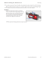
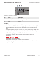
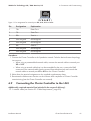
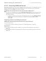
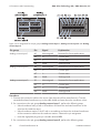
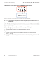
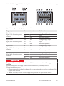
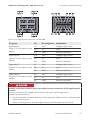
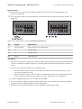
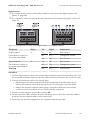
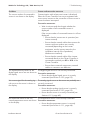
Figure 24: Pin assignment for pin group Analog current input 3
Pin
Signal
Explanation
B1
Not assigned
Reserved for future applications
B2
I+
Current input
B3
I−
Current return
B4
GND
Shield ground
Procedure:
1. Connect the connection cable to the analog signal source (see the manual from manufacturer).
Trim the unneeded insulated conductors up to the cable shield and note down the conductor
colors.
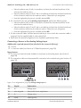
2. Connect the connection cable to the eight-pole plug:
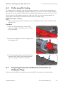
• Unlock conductor entry 4 with a screwdriver and insert the insulated conductor of the
wire into the conductor entry.
• Unlock conductor entries 2 and 3 with a screwdriver and insert the insulated conductors
of the connection cable into the conductor entries. Observe the pin assignment.
3. Insert the eight-pole plug into pin row B in terminal X8.
4. On the connection cable, mark the terminal and the pin row to which the connection cable is
assigned. Use the supplied cable tie with caption field.
5. Write down the terminal assignment on the supplied supplementary sheet.
Installation Manual
ClusterController-IA-en-14
61