1
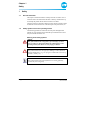
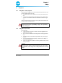
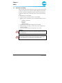
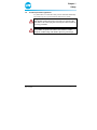
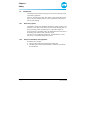
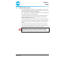
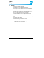
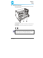
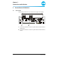
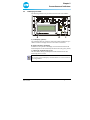
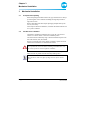
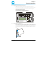
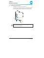
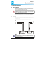
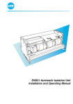
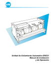
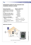
ENS26 Automatic Isolation Unit
Installation Manual
Issue 09/2005
UfE Umweltfreundliche Energieanlagen GmbH
Joachim-Jungius-Straße 9
D–18059 Rostock
Tel.: +49 3 81 / 405 97 05
Fax: +49 3 81 / 405 97 03
E-mail: [email protected]
web: www.ufegmbh.de
Note
If you have any queries and need to contact UfE GmbH, always have the
serial number close to hand in order to make reference to it. We do not
claim the documentation is free of errors and mistakes. Please inform
UfE GmbH of any errors found in the documentation.
© Copyright
This Installation Manual is the copyright of UfE GmbH.
This manual is intended for the electrician. It contains instructions and information which must not be copied, distributed or transferred by technical data methods nor used for the purpose of competition, either as an entirety or as extracts, without the necessary authorisation.
Contravention could lead to prosecution and obligation to pay damages.
All rights reserved, particularly in the case of patent application or other
registrations.
We reserve the right to make technical modifications without notice.
Note
The ENS26 isolation unit and the measuring method are protected by
patent.
Page 2 of 20
Installation Manual ENS26
Version: A.02
Issue: 20.09.2005
Table of Contents
1
Safety.......................................................................................4
1.1
1.2
1.3
1.4
1.5
1.6
1.7
1.8
1.9
2
Connections and Indicators ................................................12
2.1
2.2
3
Version: A.02
Issue: 20.09.2005
Basic configuration ......................................................17
Circuitry .......................................................................17
Disconnection..............................................................18
Function Test ........................................................................19
5.1
5.2
6
Transport and unpacking.............................................14
Conditions for installation ............................................14
Preparing the electrical/meter cabinet .........................15
Mounting on the top hat rail.........................................15
Removing from the top hat rail ....................................16
Electrical Connections .........................................................17
4.1
4.2
4.3
5
Connections ................................................................12
LCD display and LEDs ................................................13
Mechanical Installation ........................................................14
3.1
3.2
3.3
3.4
3.5
4
General information.......................................................4
Safety symbols used in this operating manual ..............4
Obligations ....................................................................5
1.3.1
Obligations of the proprietor ..........................5
1.3.2
Obligation of personnel..................................5
Guarantee and liability...................................................6
Accident prevention regulations ....................................7
Intended use..................................................................8
1.6.1
Exclusive purpose .........................................8
1.6.2
Observe information and regulations.............8
Installation and connection............................................9
Operation ....................................................................10
Rating plate and CE symbol ........................................11
Switching the system on..............................................19
Indicators during operation..........................................19
Technical Data ......................................................................20
Installation Manual ENS26
Page 3 of 20
Chapter 1
Safety
1
1.1
Safety
General information
This chapter contains information on safety and rules of conduct. It is essential to observe the information and rules so that any residual risks represented by the product do not lead to a fault or an accident.
The device must be connected to the local power supply. Therefore, all the
normal risks involved in the use of electrical power are present here, too.
1.2
Safety symbols used in this operating manual
The following symbols are used at the relevant points throughout this
manual. Pay strict attention to the information provided in these sections
and proceed with the utmost care.
Meaning of the safety symbols:
Danger
This symbol indicates the risk of fatal or personal injury if certain
rules of conduct are disregarded. When this symbol appears in the
operating manual, take all the necessary safety precautions.
Attention
This symbol indicates the risk of property damage as well as financial
and legal disadvantages (e.g. loss of rights to claims under the terms of
guarantee, liability, etc.).
Note
This symbol indicates important information on working efficiently,
economically and ecologically.
Page 4 of 20
Installation Manual ENS26
Version: A.02
Issue: 20.09.2005
Chapter 1
Safety
1.3
1.3.1
Obligations
Obligations of the proprietor
The proprietor is obliged only to allow suitably trained personnel to work
with the ENS26 isolation unit who
• are familiar with the basic regulations on safety and accident prevention,
• have read the operating manual, the chapter on safety and the safety
symbols, have understood them and confirmed this with their signature.
The proprietor must always ensure the entire product documentation is at
the disposal of operating personnel.
Danger
The proprietor bears the responsibility for safety. This responsibility
cannot be delegated.
1.3.2
Obligation of personnel
Personnel must:
• be in possession of a license to connect electronic equipment to the
public electricity supply,
• always ensure for themselves that third-parties and the equipment are
safe,
• maintain the safety and connection regulations of the power supply
provider,
• have read and understood the operating instructions, the chapter on
safety and warning labels,
• observe the applicable regulations concerning industrial safety and accident prevention.
Danger
This concerns the safety of yourself and other persons in the vicinity
of the ENS26 as well as safety when working with the mains electricity
supply.
Version: A.02
Issue: 20.09.2005
Installation Manual ENS26
Page 5 of 20
Chapter 1
Safety
1.4
Guarantee and liability
Our "General Terms of Sale and Delivery" apply. The proprietor has claim
to these on conclusion of the contract at the latest. Rights to claims under
the terms of guarantee and liability in respect of persons and property are
considered void when they are the result of one or more of the following
causes:
• Unintended use of the ENS26,
• Improper start up, operation and service of the ENS26,
• Failure to observe information in the overall documentation in respect
of
– installation, connection
– starting up
– operation
– cleaning/servicing
• Unauthorised constructional modifications to the ENS26,
• Damage through overvoltage, overload, short circuit, mechanical interference, moisture,
• Case of catastrophe caused by foreign body or Act of God.
Attention
No modification may be carried out on the ENS26 without the approval
of the manufacturer.
Attention
Never attempt to repair the device yourself. All rights to claims under
the terms of guarantee are annulled in the case of tampering.
Page 6 of 20
Installation Manual ENS26
Version: A.02
Issue: 20.09.2005
Chapter 1
Safety
1.5
Accident prevention regulations
Any faults which occur that affect safety must be eliminated immediately.
The ENS26 may not be operated until the fault has been cleared.
Danger
Solar modules conduct electricity as soon as they are exposed to daylight. Observe this when laying and connecting the cables and take the
necessary precautions.
Danger
It is forbidden to open the unit. The box can continue to conduct
dangerous residual voltage some minutes after being switched off.
Version: A.02
Issue: 20.09.2005
Installation Manual ENS26
Page 7 of 20
Chapter 1
Safety
1.6
Intended use
The ENS26 has been built according to state-of-the-art technology and accepted safety regulations.
However, when the unit is used, there remains a risk of fatal and personal
injury to the user and third-parties as well as impairment of the unit and
other property damage.
1.6.1
Exclusive purpose
The ENS26 is exclusively intended for monitoring voltage, frequency and
impedance of one phase of the electricity network at the feeding point of a
power generating system. On detecting over- and undervoltages, frequency deviation or impedance jumps, the ENS26 disconnects all poles of
the feeding point from the public electricity supply.
Any other use is considered unintended use. The manufacturer is not liable for any consequential damage in such cases.
1.6.2
Observe information and regulations
Intended use also includes
• observing all information provided in this manual and
• maintaining the connection and installation conditions prescribed by
the manufacturer.
Page 8 of 20
Installation Manual ENS26
Version: A.02
Issue: 20.09.2005
Chapter 1
Safety
1.7
Installation and connection
The unit is designed for installation in an electrical cabinet or meter cabinet. If there insufficient space in the cabinets available, a separate cabinet
must be provided for the ENS26 and contactors.
Never place the cabinet containing the ENS26 above or in the vicinity of a
heater. Pay attention to sufficient ventilation.
Connection to the public electricity supply may only be performed by a
properly qualified electrician. The safety regulations of the electricity
supply authority must be observed.
Do not place anything on the connection cable. Lay all the cables so that
they do not present a risk of tripping. Fix all cables to the wall, ceiling etc.
Pay attention to the cable cross-section requirements for all connection
cables.
Never attempt to repair the unit yourself. Opening the unit can expose
components conducting dangerously high levels of voltage. Repairs may
only be made by the manufacturer or an authorised specialist.
Danger
It is forbidden to open the unit. The unit can continue to conduct
dangerous residual voltage some minutes after being switched off.
Version: A.02
Issue: 20.09.2005
Installation Manual ENS26
Page 9 of 20
Chapter 1
Safety
1.8
Operation
Operation of the ENS26 is impermissible:
• for monitoring tasks for which the unit is not designed,
• when using accessories which have not been approved by the manufacturer,
• when the proprietor has made constructional modifications.
Functional faults must be analysed immediately. If necessary, the proprietor must request specialist assistance. The equipment may only be put
into operation again when there is no doubt about its safety.
The ENS26 is intended for operation at room temperatures between
- 20 °C and + 40 °C (also refer to Chapter 5, Technical Data).
Contact a suitably trained electrician or the manufacturer in the following
cases:
• connection cable is damaged,
• liquids or foreign bodies have got inside the unit,
• the unit has been exposed to water or rain,
• the unit has fallen down or is mechanically damaged,
• the unit behaves in a way indicating a fault (e.g. indication or message
on the optional LCD, constant switching).
Page 10 of 20
Installation Manual ENS26
Version: A.02
Issue: 20.09.2005
Chapter 1
Safety
1.9
Rating plate and CE symbol
The manufacturer has provided the following information on the ENS26
at the positions indicated:
A
B
A) Serial number
The manufacturer’s serial number for the ENS26 is provided at this point.
B) CE symbol
The CE symbol is located at the bottom right corner of the front side:
Note
Always make reference to the ENS26 serial number in the case of inquiries, orders and contracts. This simplifies communication with the
manufacturer and prevents errors when processing requests.
Version: A.02
Issue: 20.09.2005
Installation Manual ENS26
Page 11 of 20
Chapter 2
Connections and Indicators
2
2.1
Connections and Indicators
Connections
The following connections are provided at the top edge of the ENS26:
L
N
L
<EINSPEISER
A
N
<NETZ
B
A 2 connection terminals to connect one phase and the neutral conductor
(feeding unit)
B 2 connection terminals to connect one phase and the neutral conductor
(mains)
Page 12 of 20
Installation Manual ENS26
Version: A.02
Issue: 20.09.2005
Chapter 2
Connections and Indicators
2.2
LCD display and LEDs
The following indicators are provided on the front side of the ENS26:
X XXXXX
A
B
C
A) LCD display (optional)
The equipment status as well as the status of the monitored phase are provided in a 2-line LC display. Each line can contain 16 characters.
B) LEDs of the phase monitoring
In addition to the optional LCD display, the unit status and status of the
monitored phase are also indicated by the three LEDs (red, green, yellow):
C) LED of the self-monitoring (green)
This LED flashes during normal operation and indicates that the selfmonitoring feature is active.
Note
The meaning of the LCD display and LED indicators is described in the
operating manual.
Version: A.02
Issue: 20.09.2005
Installation Manual ENS26
Page 13 of 20
Chapter 3
Mechanical Installation
3
3.1
Mechanical Installation
Transport and unpacking
When transporting the ENS26 isolation unit, pay attention that it is always
protected against contact with dirt and damage through impacts and setting down too hard.
Remove the ENS26 from the transport packaging and pull off the protective foil, if necessary.
After transport and before installation, check that the ENS26 isolation unit
is in a perfect condition.
3.2
Conditions for installation
The ENS26 is intended for installation on a top hat rail in an electrical
cabinet or in a meter cabinet. It cannot be installed anywhere.
The cabinet must be sufficiently large to house the ENS26 and protect the
unit from moisture, dust, dirt and heat.
If there is not enough space in the cabinets available, a separate electrical
cabinet must be mounted to accommodate the ENS26.
Attention
Never position the electrical cabinet containing the ENS26 above or in
the vicinity of a heater. Ensure sufficient ventilation.
The ENS26 should be mounted as near as possible to the mains power
outlet and as far as possible from the electricity feeding source.
Note
These measures reduce the effect of voltage increase by the current
source.
Page 14 of 20
Installation Manual ENS26
Version: A.02
Issue: 20.09.2005
Chapter 3
Mechanical Installation
3.3
Preparing the electrical/meter cabinet
Determine the installation position of the ENS26 on the top hat rail.
Saw a cut-out in the cabinet cover at the installation position of the ENS26
so that you can see the ENS26 and its indicators (LEDs and optional
LCD) without opening the cabinet.
The cut-out must have the following dimensions:
145 mm
73 mm
X XXXXX
3.4
Mounting on the top hat rail
Set the isolation unit with its top housing holder (A) on the top hat rail and
turn it downwards against the top hat rail (B). Use a little force to press on
the bottom housing section until the housing holder engages in the top hat
rail.
A
B
Version: A.02
Issue: 20.09.2005
Installation Manual ENS26
Page 15 of 20
Chapter 3
Mechanical Installation
3.5
Removing from the top hat rail
The ENS26 can be removed from the top hat rail.
Insert the tip of a screwdriver in the grooves (A) in the clamps at the ends
of the housing. Pull the clamps downwards (B). The ENS26 is released.
Remove the ENS26 by turning it a little (C) away from the top hat rail.
C
A
B
Attention
Never remove the ENS26 from the top hat rail using brute force. This
could damage the housing holders.
Page 16 of 20
Installation Manual ENS26
Version: A.02
Issue: 20.09.2005
Chapter 4
Electrical Connections
4
4.1
Electrical Connections
Basic configuration
The ENS 26 is connected directly and without any switchin elements between the mains and the feeding point of a phase.
Danger
Connection to the public electricity supply may only be performed by a
properly qualified and authorized electrician.
The ENS26 must be protected by a pre-fuse in the respective phase of the
mains feed circuit (min. 6 A, max. 25 A). Observe the circuit diagram.
4.2
Circuitry
N
N
L
L
MAINS
FEEDER UNIT
Check that the mains power lines and power feed line (phase) are not conducting electricity.
Switch the power generator (feeder) and the ENS26 as follows:
*
L
N
FEEDER
N L
MAINS
UfE - ENS26
Note
The additional pre-fuse (*) is only necessary if the direct mains power
fuse protection exceeds 25 A.
Version: A.02
Issue: 20.09.2005
Installation Manual ENS26
Page 17 of 20
Chapter 4
Electrical Connections
The terminals on the ENS26 are arranged as follows:
Mains
Feeder
Attention
The ground conductor should always bypass the unit. The neutral conductor MUST be connected to the ENS26 otherwise the unit may be
damaged.
If the ENS26 is switched on and off by means of a system control unit, the
phase connection (L) of the ENS26 can be switched by means of a relay.
Note
When switching on via a relay, the delay until the contactors are activated can be up to 30 seconds because the ENS26 must test the power
feed conditions again.
4.3
Disconnection
Switch off the power supply to the mains power lines and the line from
the power generator (feeder).
Wait until the isolation unit has removed all the residual voltages.
Danger
The isolation unit can still conduct dangerously high residual voltage
some minutes after being switched off. Risk of accident!
Disconnect the mains power lines and the feeder line.
Insulate bare contacts from mains power lines and feeder line.
The ENS26 can then be removed from the top hat rail (also refer to
Chapter 3.5).
Page 18 of 20
Installation Manual ENS26
Version: A.02
Issue: 20.09.2005
Chapter 5
Function Test
5
5.1
Function Test
Switching the system on
Switch the isolation unit on first and then the power generator (feeder).
The ENS starts up automatically after switching on the mains supply.
The following appears on the optional LCD display after a successful selftest and mains test:
D 220,9V 49,9Hz
E26_4_0 Ok
1
When the voltage, frequency and mains impedance are in the permissible
range for 20 to 30 seconds, the relays are triggered and power feed in the
public electricity supply begins. The mains power is then monitored.
5.2
Indicators during operation
After switching on, the values for voltage, impedance and frequency are
displayed alternately (refer to the Operating Manual).
Version: A.02
Issue: 20.09.2005
Installation Manual ENS26
Page 19 of 20
Chapter 6
Technical Data
6
Technical Data
Switched power
max. 5750 W
Own consumption
1.5 W
Housing
Plastic, suitable for assembly on
the top hat rail
Overall dimensions (W x H x D)
146 mm x 111 mm x 80 mm
Cut-out dimensions (W x H)
146 mm x 73 mm
Ambient conditions
- 20 °C to + 40 °C,
10 to 90 % relative humidity,
non-condensating
Nominal current of power feeder
max. 25 A
The unit disconnects the mains under the following defined conditions (complying with standard DIN VDE 0126):
Page 20 of 20
Overvoltage
(fast shutdown)
> 300 V (response time 0.02 s)
Overvoltage
> 264 V (response time 0.2 s)
Overvoltage (average)
230 V + 10% over 10 minutes
Undervoltage
(fast shutdown)
< 130 V (response time 0.02 s)
Undervoltage
< 185 V (response time 0.2 s)
Frequency deviation
+ 0.2 Hz / -2,5 Hz
(response time 0.2 s)
RoCoF = Rate of Change of
Frequency
> 1 Hz/s
Impedance jump detection
> 0.5 Ohm (response time 0.5 s)
Installation Manual ENS26
Version: A.02
Issue: 20.09.2005