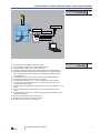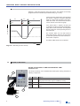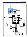
1
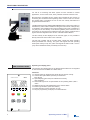
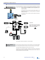
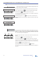
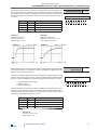
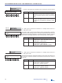
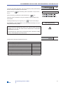
Operating and Installation Manual
iM50
Fume hood monitor face velocity
SCHNEIDER Elektronik GmbH
Phone: +49 (0) 6171 / 88 479 - 0
Fax:
+49 (0) 6171 / 88 479 - 99
Industriestraße 4
e-mail:
[email protected]
61449 Steinbach • Germany
www.schneider-elektronik.com
DECLARATION OF CONFORMITY
DECLARATION OF CONFORMITY
SCHNEIDER Elektronik GmbH hereby declares that the device:
FUME HOOD MONITOR iM50
complies with the basic requirements of the European Council Directive for
electromagnetic compatibility (89/336/EEC) and the CE Marking Directive
(93/68/EEC).
You may request a copy of the declaration of conformity at the address given
below.
SCHNEIDER Elektronik GmbH
Industriestraße 4
61449 Steinbach
Tel.:
+49 (0) 6171 / 88 479 - 0
Fax:
+49 (0) 6171 / 88 479 - 99
e-mail: [email protected]
www.schneider-elektronik.de
© 2009 SCHNEIDER Elektronik GmbH
61449 Steinbach ● Germany
Translation, reproduction and other uses, etc. - in whole or in part - are only
allowed with the explicit permission of Schneider Elektronik GmbH.
In the course of continuous product improvements we reserve the right to
make technical and and design changes.
All rights reserved.
Date: 12/2009
Operating manual ● iM50
1
SAFETY INSTRUCTIONS
1.0
SAFETY INSTRUCTIONS
Before installing and using the iM50 fume hood monitor, please read and
follow this operating and installation manual carefully.
• Installation and wiring may only be done by qualified specialists.
• Check whether the operating voltage shown on the nameplate corresponds
with the supply voltage at the site where the device will be installed.
• During installation, wiring and operation, recognised technical precepts,
particularly regulations regarding safety and accident prevention,
must be followed.
• The device should only be returned to the manfacturer for repair in the
original box.
• When you see the symbol CAUTION, we
recommend that you pay careful attention
to the explanatory text and notes.
ELECTRICAL CONNECTION
• The electrical connection must be done by a qualified electrician in
accordance with the safety precautions.
• The following rules and regulations must be followed:
VDE guidelines
Local power supplier regulations
Manufacturer wiring instructions and terminal connection
diagrams
• Connect the iM50 fume hood monitor to its own, separate circuit to protect
against overload.
• Do not do any electrical work on the device when the power supply
is switched on.
• Follow the safety regulations at all times:
- Disconnect the iM50 fume hood monitor
- Ensure that the fume hood monitor cannot be switched
on again
- Ensure that the fume hood monitor is voltage-free
OPERATING SAFETY
• Do not use the iM50 device immediately after bringing it from
an unheated room into a warm room. Condensation on
the electronic circuits can lead to severe damage. The device reaches
room temperature after approximately 2 hours.
• Always pull the mains plug or disconnect the device from the power
if objects or fluids have permeated the device or if you notice a smell or
smoke. Have the manufacturer check the device.
• Always pull the mains plug or disconnect the device from the power
supply if the case or lid of the device has to be opened.
PROPER
USE
• The iM50 fume hood monitor is intended solely for controlling and
monitoring volume flows in fume hoods in accordance with EN 14175, Part 2.
• Do not use the iM50 fume hood monitor in areas that are vulnerable to
explosion.
CE-NOTE
The iM50 fume hood monitor complies with the safety requirements of the EMC
law and the CE Marking Directive and therefore disposes of a CE Marking.
2
Operating manual ● iM50
TABLE OF CONTENTS
TABLE OF CONTENTS
1.1
Page
DECLARATION OF CONFORMITY . . . . . . . . . . . . . . . . . .
1
SAFETY INSTRUCTIONS . . . . . . . . . . . . . . . . . . . . . . . .
2
TABLE OF CONTENTS . . . . . . . . . . . . . . . . . . . . . . . . .
3
FUNCTIONAL DESCRIPTION . . . . . . . . . . . . . . . . . . . . .
4
2.1
FUNCTION DISPLAY AND CONTROL PANEL . . . . . . . . . . . .
4
2.2
FUNCTIONAL DIAGRAM FACE VELOCITY . . . . . . . . . . . . . . . .
5
2.3
PERFORMANCE FEATURES . . . . . . . . . . . . . . . . . . . . . . . .
5
3.0
OPERATING MODE FACE VELOCITY MONITORING . . . . . . . .
6
4.0
SCOPE OF DELIVERY . . . . . . . . . . . . . . . . . . . . . . . . . . . .
6
5.0
TERMINAL DIAGRAM . . . . . . . . . . . . . . . . . . . . . . . . . . . . .
7
1.0
1.1
2.0
6.0
INSTALLATION • THE FIRST THREE STEPS. . . . . . . . .
8
6.1
STEP 1 • FITTING THE MONITOR . . . . . . . . . . . . . . . . . . . . . .
8
6.2
STEP 2 • MOUNTING THE CONNECTING PIPE . . . . . . . . . . . . .
8
6.3
STEP 4 • POWER SUPPLY. . . . . . . . . . . . . . . . . . . . . . .
9
CONNECTING ADDITIONAL FUNCTIONS . . . . . . . . . . . . . .
10
7.0
7.1
CONNECTING THE RELAY OUTPUTS . . . . . . . . . . . . . . . . .
10
7.1.1
CONNECTING THE RELAY CONTACT LIGHT K1 . . . . . . . . . . . . .
10
7.1.2
CONNECTING THE RELAY CONTACT ALARM K2 . . . . . . . .
11
7.1.3
CONNECTING THE RELAY CONTACT MOTOR ON/OFF K3 . . . . . . . .
11
7.2
CONNECTING THE DIGITAL INPUT SASH > 50 cm. . . . . . . . . . . .
12
7.3
CONNECTING THE DIGITAL INPUT DAY/NIGHT . . . . . . . . . .
12
7.4
CONNECTING THE ANALOGUE OUTPUT . . . . . . . . . . . . . . .
13
7.5
CONNECTING THE SERIAL INTERFACE RS232 . . . . . . . . . . . .
13
7.6
CONNECTING THE ANALOGUE INPUT . . . . . . . . . . . . . . . . . .
13
8.0
FUNCTION DISPLAY AND CONTROL PANEL . . . . . . . . . . . . . .
14
9.0
PROGRAMMING INSTRUCTIONS VIA INTERNAL SYSTEM LEVEL .
16
9.1.1
FACE VELOCITY NIGHT-TIME OPERATION . . . . . . . . . . . . . .
17
9.1.2
FACE VELOCITY DAYTIME OPERATION . . . . . . . . . . . . . . . .
17
9.2.1
ALARM DELAY TIME . . . . . . . . . . . . . . . . . . . . . . . . . . .
18
9.2.2
DELAY OF THE INPUTS AND SWITCH TYPE DEFINITION . . . . . .
18
9.2.2.1
SENSOR ATTENUATION . . . . . . . . . . . . . . . . . . . . . . . . . . .
19
9.2.2.2
ALARM DELAY AFTER START-UP . . . . . . . . . . . . . . . . . . . . .
19
9.2.2.3
CONTACT INVERSION MALFUNCTION NOTIFICATION RELAY . . .
20
9.2.2.4
SWITCH TYPE "SASH > 50 CM" . . . . . . . . . . . . . . . . . . . . . .
20
9.2.2.5
SWITCH TYPE DAY/NIGHT . . . . . . . . . . . . . . . . . . . . . . .
20
9.3
CALIBRATION OF THE SENSOR . . . . . . . . . . . . . . . . . . . . .
21
9.4
SETTINGS ON DELIVERY
21
10.0
iM50 TROUBLESHOOTING ERRORS . . . . . . . . . . . . . . . . . . . .
22
11.0
iM50 TROUBLESHOOTING MALFUNCTIONS . . . . . . . . . . . . . .
24
12.0
MAINTENANCE . . . . . . . . . . . . . . . . . . . . . . . . . . . . . . .
25
ANNUAL FUME HOOD MAINTENANCE . . . . . . . . . . . . . . . . . .
25
13.0
12.1
TECHNICAL DATA . . . . . . . . . . . . . . . . . . . . . . . . . .
26
14.0
DIMENSIONS AND DIMENSIONAL DIAGRAMS . . . . . . . . . . . . .
27
15.0
INDEX . . . . . . . . . . . . . . . . . . . . . . . . . . . . . . . . .
28
Operating manual ● iM50
3
FUNCTIONAL DESCRIPTION
2.0
FUNCTIONAL DESCRIPTION
For use as a monitoring and alarm system for face velocities in various
applications, such as fume hoods, safety cabinets and other extraction units.
Microprocessor controlled security system with integrated air flow sensor for
monitoring the containment-safe operating status of fume hoods. An acoustic
and optical alarm is activated as soon as the face velocity falls below the
programmed threshold value.
The iM50 Airflow Monitor fulfills the EN 14175 standard. That means safety for
the laboratory worker. iM50 is suitable for all types of fume hood, making it easy
to implement new installations and retrofit existing fume hoods. Installation is
very easy and is done directly on the side bar (pilaster) of the fume hood. The
face velocity in the fume hood is identical to the face velocity measured in the
bypass with the integrated air flow sensor of the iM50 Airflow Monitor.
The face velocity is also displayed via an LED bar graph, so it is possible to
directly read off the actual value in m/s und ft/min.
The red LED, together with an acoustic alarm, signals the alarm operating
status (insufficient face velocity). The green LED signals the safe operating
status (face velocity is OK). The yellow LED signals the status "Sash > 50 cm"
(only with an additional switch provided by the customer).
2.1
FUNCTION DISPLAY
AND CONTROL PANEL
Operating and display panel
The operating and display panel of the Airflow Monitor iM50 has an integrated
air flow sensor and is available as a fitted version.
iM50
airflow monitor
0
0.3
0.5
0.7
1.0 m/s
0
60
100
140
200 fpm
Low
Functions:
LED bar graph for displaying the actual value of the face velocity
Acoustic and optical alarm (red LED) for insufficient
face velocity
Optical display (green LED) for sufficient face velocity
(safe operation)
Yellow flashing LED as an optical alarm for the operating status „Sash >
50cm"
RESET button for acknowledgement of the acoustic alarm
Button Light ON/OFF (fume hood interior)
Button ON/OFF for direct actuation of a fan
Plug for programming via laptop or PC2500 software
Okay
I/O
www.schneider-elektronik.com
4
Operating manual ● iM50
FUNCTION DISPLAY AND OPERATING PANEL • FUNCTIONAL DIAGRAM
FUNCTIONAL DIAGRAM
face velocity
2.2
PERFORMANCE
FEATURES
2.3
PLUG IN POWER SUPPLY
100...240V AC/24V DC
Fume hood
a irflow m onitor iM5 0
airflow monitor iM50
Integrated
air flow sensor
airflow monitor iM50
24V DC
Day- / Night operation
Analogue output
I/O
Supply
air
Relay outputs
RS 232
Monitoring
acc. to EN 14175
Laptop
Microprocessor controlled monitoring system
Low cost airflow monitor as a compact fitted version
External mains adapter 100...230V AC/24V DC
All system data are saved mains voltage failure-safe in the EEPROM
Integrated password protected operating interface for programming the
face velocity alarm values (daytime and night-time operation) and the
alarm delay time
Programming of all system values via laptop with PC2500 software
Monitoring of supply air and exhaust air systems
Integrated air flow sensor 0.2...1 m/s for measuring the face velocity
monitoring of fume hood operation in accordance with EN 14175 with
acoustic and optical alarms
LED bar graph for displaying the actual values of the face velocity m/s und
ft/min
Optical and optionally acoustic alarm for the operating status “Sash >
50cm”
Programming of a second monitoring value (reduced face velocity during
night-time operation)
Button Light ON/OFF (fume hood interior)
Button ON/OFF for direct actuation of a fan
Suitable for all fume hood constructions
Operating manual ● iM50
5
OPERATING MODE • DELIVERY AND INSTALLATION
3.0
MONITORING THE FACE VELOCITY
Diagram 1 shows the monitoring of the face velocity. The setpoint can be freely
programmed and is indicated by the dashed line (e.g. 0.3 m/s).
Okay
Alarm
Air velocity
green
red
If the actual value measured by the integrated
flow sensor ≥ setpoint, the green LED (OK)
lights up to signal safe operation of the monitored fume hood. The measured actual value
can be read off on the LED bar graph.
Okay
green
oberer Grenzwert
Actual value
unterer Grenzwert
If the actual value < setpoint, the red LED
(LOW) lights up after the programmable alarm
delay time. At the same time, the integrated
buzzer signals the unsafe operating status of
the fume hood.
The acoustic alarm can be reset with the
Alarm Reset button, while the red LED lights
up until safe operation has been restored, i.e.
actual value ≥ setpoint.
This alarm fulfills the EN 14175 standard.
time
Diagram 1: Monitoring the face velocity
4.0
SCOPE OF DELIVERY
SCOPE OF DELIVERY FUME HOOD MONITOR iM50
Standard model
The scope of delivery of the standard iM50 model (face velocity) includes the
following components:
3
Pos.
Number
Object
1
1
Control electronics with integrated air flow sensor, LED
bar graph and function keys in installation housing
2
1
External mains adapter 100...240V AC
3
1
Hose connection to the fume hood interior with an end
piece
1
2
6
Operating manual ● iM50
TERMINAL DIAGRAM
5.0
Exhaust
air
TERMINAL DIAGRAM
Fume hood
airflow monitor iM50
air flow m onitor iM 5 0
Integrated
airflow sensor
airflow monitor iM50
I/O
air in take
Monitoring
according
to EN 14175
Analogue input A1-In
open: 0...5V
closed: 0...10V
ANALOGUE OUTPUT A1-Out
A1-Out
0(2)...10V DC/10mA
0(4)...20mA
Load resistor
500 Ohm
Analogue output A1-Out
open: 2...10V/4...20mA
closed: 0...10V/0...20mA
GND
0/4…20mA
0/2...10V
X7
15
16 X8
17
14
13
12
JP3
JP2
+24V DC
0...5/10V DC
GND
ANALOGUE INPUT A1-In
0...5/10V DC/1mA
A1-In
Integrated
airflow sensor
PIC-Programmer
Bootloader
On/Off
JP1
X9
1
2
3
11
JP4
X6 10
9
CPU
iM50
RS 232
8
7
X5
X10
K2
3
5
COM
X3
NO
COM
PLUG IN POWER SUPPLY
100...240V AC/24V DC
6
X2
OPERATION = Relay ON
FAULT ALARM = Relay OFF
NO
4
ON
24V DC
L
ON/OFF
Relay contact
Max.: 3A / 60VAC
Max.: 8A / B16
L1,2,3 (115/230VAC)
LIGHT ON/OFF
N
FAULT ALARM
Relay contact
Max.: 3A / 60VAC
POWER LIGHT
FUME HOOD
L
N
230 VAC
50/60Hz
DIGITAL INPUTS
Max. cable length < 3m
Day/Night monitoring
K3
2
X1
Laptop
Sash > 50 cm
In1
Relay
On/Off
K1
1
In2
GND
+24V DC
X4
Relay
Light
Relay
Fault alarm
+24V DC
FUME HOOD MONITOR acc. to EN 14175
with integrated airflow sensor
Terminal diagram, complete
Rev.:
1.0
Operating manual ● iM50
iM50
Date:
15. Dec. 2008
7
INSTALLATION
6.0
INSTALLATION • THE FIRST THREE STEPS
ALWAYS FOLLOW THE
MOUNTING INSTRUCTIONS!
The following mounting methods are permissible for the iM50 fume hood
controller:
• Variable fitting of the iM50 monitor in the fume hood side bar.
• Make sure that the integrated air flow sensor is not directly influenced by
turbulent air (e.g. air outlets in the laboratory, in the vicinity of
doors, windows, etc.).
CAUTION! With all other types of mounting the measuring signal of the
air flow sensor can be unstable.
In all cases, after mounting the evaluation electronics during commissioning, a reference measurement with a hydrometric vane and possibly calibration of the air flow sensor must be carried out.
During installation and operation it is essential to ensure that no shavings, dirt
or contaminants get into the air flow sensor. Fit the hose connection of the evaluation electronics in the fume hood interior in such a way that condensation
cannot permeate the air flow sensor.
STEP 1
6.1
FITTING THE
MONITOR
Install the iM50 in a visible position on the fume hood side bar. The display with
the bar graph should be mounted at eye-level for easy reading. The fitting position is variable, but preferably vertical.
STEP 2
6.2
MOUNTING THE
CONNECTING HOSE
The connecting hose from the evaluation electronics (air flow sensor) to the
fume hood interior that is included in the delivery must be careful connected
without buckles or bends.
The connecting hose must fit exactly on the end piece nozzle and on the
air flow sensor nozzle. Untight mounting results in imprecise measuring
results as a result of infiltrated air.
IMPORTANT!
Ensure that the air can flow freely through the flow sensor. If the flow pipe (connecting pipe) or the inflow vents are dirty or covered, the measuring result may
be falsified.
The end piece with the connecting hose must be visible in the fume hood interior
and must not be covered up (e.g. behind baffles or deflectors, etc.).
The evaluation electronics with the integrated air flow sensor must not be mounted in the vicinity of air outlets. Ensure a laminar flow of air without hindrances
in the flow sensor.
8
Operating manual ● iM50
INSTALLATION
STEP 3
Plug the mains adapter cable into plug X4 on the iM50 control board (rear side)
and plug the mains adapter into the mains socket.
POWER SUPPLY
6.3
When the supply voltage (100...240V AC) has been switched on, the LOW
or OK LED (depending on the face velocity) must light up and the LED bar
graph must display the actual value.
The components required for the monitoring operating mode (face velocity) have now been connected.
If no further additional functions or relay outputs are needed, you can now
move on to the programming instructions (Chapter 9.0). After all important
parameters have been programmed in accordance with Chapter 9.0, the
iM50 fume hood monitor is ready for operation.
The terminal connections for the additional functions and relay outputs
are described in chapter 7.0.
Operating manual ● iM50
9
CONNECTION • RELAY OUTPUTS
7.0
CONNECTING ADDITIONAL FUNCTIONS
7.1
CONNECTING THE
RELAY OUTPUTS
Exhaust
air
In the full construction a maximum of three relays are populated on the iM50
control board. The relay outputs are potential-free and are intended for malfunction notification and feedback to the building services management (BSM).
The maximum ohmic contact load of the relay Light K1 is 12
A (230V AC). this relay is for direct actuation of fluorescent
lamps (max. 58 W).
The maximum ohmic contact load of the relays K2 and K3 is
3 A (230V AC).
Fume hood
airflow monitor iM50
air flow m onitor iM 5 0
Integrated
airflow sensor
airflow monitor iM50
I/O
air in take
Monitoring
according
to EN 14175
Analogue input A1-In
open: 0...5V
closed: 0...10V
ANALOGUE OUTPUT A1-Out
A1-Out
0(2)...10V DC/10mA
0(4)...20mA
Load resistor
500 Ohm
Analogue output A1-Out
open: 2...10V/4...20mA
closed: 0...10V/0...20mA
GND
0/4…20mA
0/2...10V
X7
15
16 X8
17
14
13
12
JP3
JP2
+24V DC
0...5/10V DC
GND
ANALOGUE INPUT A1-In
0...5/10V DC/1mA
A1-In
Important!
Integrated
airflow sensor
PIC-Programmer
Bootloader
On/Off
JP1
X9
1
2
3
11
JP4
X6 10
9
CPU
iM50
RS 232
8
7
X5
X10
K2
3
4
5
6
DIGITAL INPUTS
Max. cable length < 3m
NO
COM
X3
PLUG IN POWER SUPPLY
100...240V AC/24V DC
COM
X2
OPERATION = Relay ON
FAULT ALARM = Relay OFF
NO
Day/Night monitoring
ON
24V DC
L
ON/OFF
Relay contact
Max.: 3A / 60VAC
LIGHT ON/OFF
Max.: 8A / B16
L1,2,3 (115/230VAC)
N
FAULT ALARM
Relay contact
Max.: 3A / 60VAC
POWER LIGHT
FUME HOOD
L
N
230 VAC
50/60Hz
In1
Ensure that connected constant
loads are properly protected
against short circuiting!
K3
2
X1
Laptop
GND
+24V DC
Sash > 50 cm
Relay
On/Off
K1
1
In2
X4
Relay
Light
Relay
Fault alarm
+24V DC
The meaning of the relay outputs K1 to K3 is as follows:
7.1.1
CONNECTING THE
RELAY CONTACT
LIGHT K1
The Light relay (K1) pulls in when the Light on/off button on the function display
and control panel is pressed and drops out when the button is pressed again.
This relay switches the lighting in the fume hood on and off.
The phase (L) for the fume hood light is supplied on terminal X2.3 and switched
via the K1 relay contact on terminal X2.4. Neutral (N) and protective earth are
connected directly to the fume hood light.
10
Operating manual ● iM50
CONNECTION • RELAY OUTPUTS • EXTERNAL POWER SUPPLY CONNECTION
In the case of a group alarm, the malfunction notification relay (K2) drops out
and thus signals the malfunction status. Malfunctions may be, for example, insufficient exhaust air volume and internal errors.
CONNECTING THE
RELAY CONTACT
MALFUNCTION
NOTIFICATION K2
7.1.2
The relay Motor on/off K3 pulls in when the iM50 fume hood monitor is switched
on. This is done by pressing the I/O (on/off) button on the function display and
control panel.
CONNECTING THE
RELAY CONTACT
MOTOR ON/OFF K3
7.1.3
This relay switches, for example, an exhaust air fan on or off (via a separate
contactor, which is actuated by the K3 relay). The relay contact can then be
used as an on/off notification for the building services management (BSM).
Operating manual ● iM50
11
CONNECTION • DIGITAL INPUTS
7.2
CONNECTING THE
DIGITAL INPUT
SASH > 50 cm
Is only connected if sash monitoring is desired. The input is not galvanically separated and is suitable for direct actuation with potential-free contacts.
The yellow LED "Close sash" flashes when the sash is opened more than 50
cm and thus warns the user that the fume hood is an unsafe operating status
(insufficient exhaust air volume flow).
The Sash digital input is not galvanically separated. Actuation is
done directly via potential-free
contacts.
The LIMIT SWITCH SASH > 50 cm on terminals X6.9 to X6.11 signals the sash
position > 50 cm. Optionally a potential-free contact or an electronic proximity
switch can be connected.
MOUNTING THE LIMIT SWITCH SASH > 50 cm
The maximum cable length is limited to 3m.
The LIMIT SWITCH SASH > 50 cm should preferably be mounted such that it
is directly activated by the sash (e.g. bistable dry reed contact). If the sash is >
50 cm open, the bistable reed contact remains closed (normally closed contact)
or open (normally open contact) until the sash underruns the opening height of
50 cm.
The input current is ≤ 2mA per
input.
The switch type (normally open or normally closed) can be programmed in the
settings menu.
7.3
Is only connected if day/night monitoring is desired. The input is not galvanically
separated and is suitable for direct actuation with potential-free contacts.
CONNECTING THE
DIGITAL INPUT
DAY/NIGHT
The maximum cable length is limited to 3m.
During daytime or night-time operation the corresponding programmed face velocity is monitored and if it is underrun (actual value < setpoint), an error alarm
is signaled (red LED and buzzer).
Switching from daytime to night-time operation is done via the X5.7 and X5.8
terminals (daytime operation = contact open).
The input current is ≤ 2mA per
input.
12
Operating manual ● iM50
CONNECTION • ANALOGUE OUTPUT • ANALOGUE INPUT
The analogue output on terminal X8.15 (GND) and terminal X8.17 (+) provides
the exhaust air actual value as an analogue signal (0)2 ... +10 VDC. The current
load may not exceed a maximum of 10mA.
The analogue output A1-Out is not galvanically separated.
Optionalls the A1-Out analogue output is also available as a current interface.
The current is tapped 0/4...20 mA via terminal X8.15 (GND) and terminal X8.16
(0/4...20 mA).
CONNECTING THE
ANALOGUE OUTPUT
7.4
When making the electrical
connection it is essential to
ensure correct + and – (GND)
polarity!
Connect load resistor 500Ω on terminal X8.15 and X8.16 if the current
output is unused!
The entire programming of the iM50 monitor is done via the RS232 serial interface on the 9-pole plug X10 using the PC2500 PC software installed on a laptop. All values can be clearly and easily read out and programmed. In addition
to the laptop, programming can also be done via the integrated operating level.
The analogue input on terminal X7.12 (GND) and terminal X7.13 can be switched between 0...5V DC or 0...10V DC. To do this, the JP2 jumper must be
open (0...5V DC) or connected (0...10V DC).
CONNECTING THE
SERIAL
INTERFACE RS232
7.5
CONNECTING THE
ANALOGUE INPUT
7.6
The analogue input is reserved for special functions.
Operating manual ● iM50
13
FUNCTION DISPLAY AND CONTROL PANEL
8.0
FUNCTION DISPLAY AND CONTROL PANEL
The function display with integrated operating panel has an LED bar graph for displaying the actual value of the face
velocity.
Access to the system level is via a password (numerical value). At the system level the most important parameters for
the device can be set via the integrated operating panel. This direct quick access via the system level particularly makes
sense when a laptop with the PC2500 programming software is not available.
This yellow LED flashes to signal an optical alarm when the
sash is opened >50cm. This
LED warns the user that operation of the fume hood may
be unsafe. The sash must be
closed.
This blue LED bar graph displays the actual value of the
face velocity from 0...1.0 m/s
or 0...200 fpm.
This green LED lights up in the
normal operating state, i.e. the
fume hood is operating with
sufficient exhaust air volume
flow and is therefore within a
safe range.
With the LIGHT button the interior lighting of the fume hood
can be switched on and off. At
system level this entry key has
the function (+).
This red LED lights up to signal a malfunction, i.e. the
fume hood is operating with
insufficient face velocity and is
therefore not contaminent-safe. With the RESET button the
acoustic alarm (malfunction
due to insufficient face velocity) can be acknowledged. The
optical alarm cannot be acknowledged and is only reset
when sufficient volume flow is
available.
With the RESET/QUIT button the
acoustic alarm (malfunction due
to insufficient face velocity) can be
acknowledged. The optical alarm
cannot be acknowledged and is
only reset when sufficient exhaust
air volume flow is available. At system level this entry key has the
function (-).
14
With the I/O key the monitor is
switched on and off. The operating mode of the LED bar
graph shows that the monitor
is switched on. At system level this input key has the function (ENTER).
Operating manual ● iM50
FUNCTION DISPLAY AND CONTROL PANEL
left blank for notes
Operating manual ● iM50
15
PROGRAMMING INSTRUCTIONS • KEY FUNCTIONS iM50
9.0
PROGRAMMING INSTRUCTIONS • iM50 PARAMETERS VIA INTERNAL SYSTEM LEVEL
Programming of the internal
system level via a second
key assignment
I/O
SWITCH THE iM50 ON
(POWER ON)
The following sections describe the programming of the parameters via the internal system level, as this is most suitable for use in the field. If you use a
laptop with the PC2500 software to program the parameters, you can also follow the programming instructions described here. The menu items and settings
have the same meaning.
When the iM50 power supply is switched on (Power ON) and after the internal
self-test, the face velocity actual value appears on the LED bar graph and, depending on the operating status, also the red (LOW) or green (OK) LED.
If the face velocity cannot be measured or is below the defined setpoint, or if the
connecting hose to the fume hood interior is not correctly installed, after a short
time the red status LED (LOW) lights up and signals insufficient face velocity.
Der LED bar graph displays the actual value 0...0.1 m/s.
iM50
airflow monitor
Setting the iM50 parameters is done via the password-protected integrated system level or with a laptop with the PC2500 software installed.
At the same time the acoustic alarm is sounded, which can be reset
0
0.3
0.5
0.7
1.0 m/s
0
60
100
140
200 fpm
RESET
with the key:
Okay
If there is sufficient face velocity, the green status LED (OK) lights up and the
LED bar graph displays the actual value. The acoustic alarm is automatically
reset if there is sufficient face velocity.
◄
Low
I/O
◄
◄
Access to programming is password-protected.
www.schneider-elektronik.com
ENTERING THE PASSWORD
FOR ACCESS TO THE
SYSTEM LEVEL
By pressing the keys
and
for entry of the password.
at the same time, you move to the screen
Keep the Minus and Plus keys pressed for at least 3 s. The red, green and yellow LEDs go out. The left blue LED of the LED bar graph flashes.
With the Plus key you can move the flashing cursor to the right, with the Minus
key to the left in order to set the password.
Entering the programming password
0
0,3
0,5
0,7
1,0
If the cursor is positioned over an LED that is switched on, it flashes rapidly,
if it is positioned over an LED that is switched off, it flashes slowly. By briefly
pressing the Enter
m/s
key
0
60
100
140
200
fpm
I/O
the LED is switched on or off.
The LEDs that are switched on represent the password.
Currently you only have to set the LED at 0.1 m/s. By pressing the Enter key for
a long time (>1 s) I/O
the password is confirmed and you move automatically to the first parameter
"Face velocity - Night-time operation".
16
Operating manual ● iM50
PROGRAMMING INSTRUCTIONS • iM50 PARAMETERS • SETPOINTS
Here you can set the threshold for underrun of the face velocity during nighttime
operation (reduced operation).
Setpoint face velocity
9.1
Face velocity
Night-time operation
(reduced operation)
9.1.1
The red LED flashes. The blue LED shows the last value that was entered, e.g.
0.3 m/s or 60 fpm. With the Plus key
to the right, with the Minus key
you can move the blue LED
0
0,3
0,5
0,7
1,0
m/s
0
60
100
140
200
fpm
to the left in order to set a new value.
The incremental step size is 0.05 m/s or 10 fpm. For example, to represent 0.35
m/s the LEDs light up at 0.3 m/s and 0.4 m/s.
With the Enter key (press > 1 s)
Setting: 0.3 m/s or 60 fpm
the new value is confirmed and you
I/O
move automatically to the next parameter "Face velocity - daytime operation".
Setting: 0.35 m/s or 70 fpm
0
0,3
0,5
0,7
1,0
m/s
0
60
100
140
200
fpm
Setting: 0.4 m/s or 80 fpm
0
0,3
0,5
0,7
1,0
m/s
0
60
100
140
200
fpm
Face velocity
Daytime operation
(normal operation)
Here you can set the threshold for underrun of the face velocity during daytime
operation (normal operation).
9.1.2
The green LED flashes. The blue LED shows the last value that was entered
Setting: 0.3 m/s or 60 fpm
e.g. 0.3 m/s or 60 fpm. With the Plus key
to the right, with the Minus key
you can move the blue LED
0,3
0,5
0,7
1,0
m/s
0
60
100
140
200
fpm
to the left in order to set a new value.
The incremental step size is 0.05 m/s or 10 fpm. For example, to represent 0.35
m/s the LEDs light up at 0.3 m/s and 0.4 m/s.
With the Enter key (press > 1 s)
0
I/O
the new value is confirmed and you
Setting: 0.4 m/s or 80 fpm
0
0,3
0,5
0,7
1,0
m/s
0
60
100
140
200
fpm
move automatically to the next parameter "Enter the alarm delay time".
Setting: 0.5 m/s or 100 fpm
Operating manual ● iM50
0
0,3
0,5
0,7
1,0
m/s
0
60
100
140
200
fpm
17
PROGRAMMING INSTRUCTIONS • iM50 PARAMETERS • SYSTEM VALUES
9.2
System values
9.2.1
Alarm delay time
The alarm delay time defines how long the predefined day/night setpoint must
be underrun before an alarm is signalled.
The yellow LED flashes. The blue LED shows the last value that was entered
No alarm delay
e.g. 35 s. With the Plus key
0
0,3
0,5
0,7
1,0
with the Minus key
0
60
100
140
200
you can move the blue LED to the right,
m/s
fpm
to the left in order to set a new value.
The incremental step size of the alarm delay is 5 s. For example, to represent 35
s the LEDs light up at 30 s and 40 s.
With the Enter key (press > 1 s)
35 s alarm delay
0
0,3
0,5
0,7
1,0
m/s
0
60
100
140
200
fpm
I/O
the new value is confirmed and you
move automatically to the next parameter "Delay of the inputs and switch type
definition".
100 s alarm delay
0
0,3
0,5
0,7
1,0
m/s
0
60
100
140
200
fpm
9.2.2
Delay of the inputs
and switch type definition
Alarmverzögerung
nach dem
Einschalten
Sensordämpfung
0
0,3
0,5
In this input mode the LED bar graph is divided into three different input groups.
With the four LEDs 0...0.3 you can set the sensor attenuation, with the four
LEDs 0.4...0.7 the alarm delay time after switching on and with the three LEDs
0.8...1.0 the switch type for the digital inputs.
Schaltertyp
Digitaleingang
The red and green LEDs flash. The blue LEDs show the last value that was
entered.
0,7
1,0
m/s
With the Plus key
0
60
100
140
200
fpm
you can move the flashing cursor
to the right, with the Minus key
to the left in order to set a new value.
If the cursor is positioned over an LED that is switched on, it flashes rapidly, if it is
positioned over an LED that is switched off, it flashes slowly. By briefly pressing
the Enter key
I/O
the LED is switched on or off.
By pressing the Enter key for a long time (>1 s)
I/O
all settings
are confirmed and you move automatically to the next parameter "Calibration of
the sensor".
.
18
Operating manual ● iM50
Increases the time constant
PROGRAMMING INSTRUCTIONS • iM50 PARAMETERS • SYSTEM VALUES
The sensor signal of the air flow sensor is attenuated by a low-pass filter. The
time constant of the low-pass filter can be adjusted. After it has passed through
the low-pass filter, the signal is displayed and can be tapped on terminal X8.
The time constant can be set with an increment of 0.625 s within the range of
0...9.375 s.
LED
State
0.0 m/s
ON
Increases the time constant by 0.625 s
0.1 m/s
ON
Increases the time constant by 1.25 s
0.2 m/s
ON
Increases the time constant by 2.5 s
0.3 m/s
ON
Increases the time constant by 5.0 s
Sensor attenuation
9.2.2.1
Setting: 9.375 s attenuation
0
0,3
0,5
0,7
1,0
m/s
0
60
100
140
200
fpm
Meaning
Example 1:
Analogue output 10 V
LED 0.2 m/s = ON
Time constant = 2.5 s
Example 2:
Analogue output 10 V
LED 0+0.1+0.2+0.3 m/s = ON
Time constant = 9.375 s
Alarm delay after
switching on
After switching on, the red LED (LOW=underrun) always lights up first. When the
face velocity reaches or exceeds the underrun threshold, the green LED (OK)
lights up and the red LED goes out.
During the predefined alarm delay time the malfunction relay K2 does not drop
out even if the volume of air is too low. It is only activated after the predetermined
time (0 to 150s). This applies to the following methods of switching on or over:
■ Connecting the power supply
■ Button On/Off
■ Switch to day/night
9.2.2.2
Setting: 150 s alarm
delay
0
0,3
0,5
0,7
1,0
m/s
0
60
100
140
200
fpm
This function does not generate an alarm for example, if the exhaust fan is switched on but only reaches its full suction capacity after a specific period of time.
The alarm delay time after switching on is given in seconds and can be set at
increments of 10 s within the range 0...150 s.
LED
State
Meaning
0.4 m/s
ON
Increases the alarm delay by 10 s
0.5 m/s
ON
Increases the alarm delay by 20 s
0.6 m/s
ON
Increases the alarm delay by 40 s
0.7 m/s
ON
Increases the alarm delay by 80 s
Example 3:
LED 0.4+0.6 m/s = ON
alarm delay = 50 s
Operating manual ● iM50
19
PROGRAMMING INSTRUCTIONS • iM50 PARAMETERS • SYSTEM VALUES
9.2.2.3
Contact inversion
Malfunction
notification relay
Setting: Contact inverted
0
0,3
0,5
0,7
1,0
m/s
0
60
100
140
200
fpm
9.2.2.4
Switch type
Sash >50 cm
0
0,3
0,5
0,7
1,0
m/s
0
60
100
140
200
fpm
Switch type
Day/night
State
ON
Meaning
Inverted. If there is a malfunction, the malfunction
notification contact is closed. If there is no malfunction or if the iM50 is without current, the contact is
open.
0.8 m/s
OFF
Not inverted. If there is no malfunction, the contact
is closed. If the iM50 is without current or if there is
a malfunction, the malfunction notification contact
is open.
According to EN 14175 fume hood sashes must be equipped with a mechanical lock at a sash opening of 50cm. If the sash is opened more than 50cm, the
mechanical lock must be released. In accordance with this standard, a flashing
yellow LED on the display signals the state „Sash opening > 50cm“ (alarm).
LED
State
0.9 m/s
ON
Meaning
Switch type = normally closed
Contact closed = yellow LED flashes (>50cm)
Contact open = yellow LED off
0.9 m/s
OFF
Switch type = Normally open
Contact closed = yellow LED off
Kontact open = yellow LED flashes (>50cm)
The switch type on terminal X5 is defined as a normally closed contact or a
normally open contact.
Setting: Contact = normally
closed
0
0,3
0,5
0,7
1,0
m/s
0
60
100
140
200
fpm
20
LED
0.8 m/s
The switch type on terminal X6 is defined as a normally closed contact or a
normally open contact.
Setting: Contact = normally
closed
9.2.2.5
The contact of the malfunction notification relay on terminal X1 can be inverted.
Switching from daytime to night-time operation is done via the X5 terminal. During daytime or night-time operation the respective programmed face velocity is
monitored.
LED
State
Meaning
1.0 m/s
OFF
Switch type = normally closed
Contact closed = Night-time operation
Contact open = Daytime operation
1.0 m/s
ON
Switch type = Normally open
Contact closed = Daytime operation
Contact open = Night-time operation
Operating manual ● iM50
RROGRAMMING INSTRUCTIONS • iM50 PARAMETERS • SYSTEM VALUES
Calibration of the
sensor
The green and yellow LEDs flash. The current measuring value (actual value) of
the face velocity is indicated by the blue LEDs.
With the Plus key
sary to
Actual value: face velocity
the measuring value is increased. It may be neces-
press the Plus key several times. With the Minus key
I/O
0
0,3
0,5
0,7
1,0
m/s
0
60
100
140
200
fpm
the
measuring value is decreased. It may be necessary to press the Minus key
several times.
Pressing the Enter key for a long time (>1 s)
9.3
confirms the settings.
Programming is now completed. You are returned automatically to the operating mode (monitoring mode).
End of programming
For calibration the sensor must be fitted in a suitable location on the fume
hood and connected. With the sash open 10 cm, the fume hood is set using
a damper to e.g. 0.5 m/s. This value must be checked with an anemometer
measurement on the sash.
By pressing the Plus or Minus key, the measuring value of the iM50 is calibrated to the value displayed by the anemometer.
Settings on
delivery
On delivery the following configurations are set:
9.4
iM50 Settings on delivery
Face velocity night-time operation
0.3 m/s
Face velocity daytime operation
0.6 m/s
Alarm delay time in the case of an underrun
10 s
Response time of the sensor
1.25 s
Alarm delay time after switching on
60 s
Inversion of the malfunction notification relay
Not inverted
Switch type for Close sash
Normally open
Switch type for day/night switching
Normally closed
Operating manual ● iM50
21
iM50 TROUBLESHOOTING ERRORS
10.0
iM50-TROUBLESHOOTING ERRORS
Error:
Flow sensor not functioning properly.
Cause:
The flow sensor is faulty.
Error correction:
Replace the iM50 device.
Check:
Select the menu item Calibration of the sensor (see Chapter 9.3). Check the actual value when the
sash and slide windows are shut (approx. 0.5...>1m/s). When a slide window or the sash is opened
the actual value must initially decrease. If an external controller is connected, depending on the sash
position, a specific value is regulated.
Cause:
The flow velocity is not displayed properly.
Error correction:
Adjust the offset face velocity (calibration with redundant measurement in the sash area).
Check:
Calibrate the flow sensor. Under the menu item Calibration of the sensor (see chapter 9.3), adjust
the flow sensor so that the value in the open sash area - redundantly measured with a calibrated
anemometer - corresponds to the displayed face velocity value of the flow sensor. Depending on
how it is fitted, the flow sensor of the iM50 must be calibrated accordingly.
Note:
The flow sensor is calibrated. The face velocity (m/s) displayed on the LED bar graph must be the
same as the redundantly measured face velocity in the area of the open sash.
Cause:
The connecting hose of the flow sensor is not correctly mounted.
Error correction:
The connecting hose must be fed into the fume hood interior without buckles or bends and must be
precisely fitted to its end pieces. The end of the pipe (inflow into the fume hood) must be visible from
the interior of the fume hood. It must not, for example, be mounted behind an air baffle.
There should be no air flow or turbulence directly in front of the iM50 air inlet grate (e.g. directly
underneath air vents in the ceiling).
Make sure that the inflow area and the end of the pipe (inflow into the fume hood) are not dirty, blocked or covered.
Check:
Select the menu item Calibration of the sensor (see Chapter 9.3). Check the actual value when the
sash and slide windows are shut (approx. 0.5...>1m/s). When a slide window or the sash is opened
the actual value must initially decrease. If an external controller is connected, depending on the sash
position, a specific value is regulated.
Note:
The flow sensor is calibrated. The face velocity (m/s) displayed on the LED bar graph must be the
same as the redundantly measured face velocity in the area of the open sash.
22
Operating manual ● iM50
iM50 TROUBLESHOOTING ERRORS
left blank for notes
Operating manual ● iM50
23
iM50 TROUBLESHOOTING
11.0
iM50-troubleshooting malfunctions
The following table will help you to analyse and correct errors or malfunctions and their possible causes.
Error:
LEDs or LED bar graph on the function display do not light up.
Causes:
Power supply (mains adapter) not connected or faulty.
Error:
The actual value displayed on the LED bar graph is not identical with the externally measured
actual value.
Causes:
Unsuitable or incorrect fitting of the flow sensor.
Flow sensor not calibrated. Se menu item Calibration of the sensor (Chapter 9.3).
Connecting hose from the flow sensor to the fume hood interior is not correctly mounted.
Error:
Function display not working correctly (LOW display always red).
Causes:
Check the setpoint settings.
Check if there is sufficient exhaust air.
Measure the minimum duct pressure - it should be ≥ 100 Pascal (depending on the fume hood
construction).
Check whether the exhaust air pipe on the fume hood has the correctly dimensioned pipe diameter
for the required exhaust air volume flow.
Error:
Function display not working correctly (OKAY display always green).
Causes:
Check the setpoint settings.
Error:
Function display not working correctly (yellow LED flashes continuously).
Causes:
"Sash > 50 cm" contact not connected.
Switch type "Sash > 50cm“ (N.O., N.C.) incorrectly programmed (see Chapter 9.2.2.4)
24
Operating manual ● iM50
iM50 TROUBLESHOOTING • MAINTENANCE
Maintenance
12.0
Yearly
fume hood
maintenance
12.1
Maintenance of the iM50 fume hood monitor should be done at the same time as
the yearly maintenance of the fume hood.
During yearly fume hood maintenance, among other things a function test with
acoustic and optical alarm must be carried out (cover the sensor air inlet) and
the programmed setpoints checked.
After this, compare the actual values displayed by the LED bar graph with a redundantly measured measuring value (hot wire or vane anemometer).
Make sure that the connecting hose from the sensor to the fume hood interior is
not damaged or bent and fits tightly on the sensor and the end piece.
Operating manual ● iM50
25
TECHNICAL DATA
13.0
Technical data
General
Mains adapter
Max. charging rate
Max. power input
Reactivation time
Operating temperature
Humidity
Case
Protection type
Material
Colour
Dimensions (LxWxH)
Weight
Terminals
Relay outputs
Number
Contact type
Max. switching voltage
Max. continuous current
IP 20
plastic
white, RAL 9002
(134 x 80 x 40) mm
approx. 1.0 kg
screw terminal 0.75 mm2
1 relay (K3) for light
front contact
250V AC
8A for fluorescent lamps
(max. 58W)
2 relays (K1, K2)
changeover contact
250V AC
3A
Analogue output
Exhaust air actual value
Analogue input
Setpoint
2 inputs, 24V DC/2mA
potential-free contact,
maximum cable length <
3m
0(2)...10VDC, 10mA or
0(4)...20mA
(load resistor = 500 Ω)
0(2)...5/10VDC, 1mA
Integrated air flow sensor
Measuring principle
dynamic, hot wire
anemometric principle
Measuring range
0.2...1 m/s
Response time
<100 ms
Subject to change without notice • All rights reserved. © SCHNEIDER
Number
Contact type
Max. switching voltage
Max. continuous current
110/230V
AC/50/60Hz/+-15%
100 mA
10 VA
600ms
0 OC to +55 OC
max. 80 % relative, noncondensing
Digital inputs
Number
Actuation
26
Operating manual ● iM50
DIMENSIONS • DIMENSIONAL DIAGRAMS
Dimensions • Dimensional diagrams
Case iM50: Top view
Case iM50: Side view
84
33
iM50
airflow monitor
0
0.3
0.5
0.7
1.0 m/s
0
60
100
140
200 fpm
Low
14.0
Okay
I/O
www.schneider-elektronik.com
Case iM50: Section
78
Subject to change without notice • All rights reserved. © SCHNEIDER
39
Operating manual ● iM50
27
INDEX
15.0
Index
A
I
Actual values 17
Alarm delay after switching on 19
Alarm delay time 5, 6, 17, 18, 19, 21
iM50 PARAMETERS VIA THE INTERNAL SYSTEM
LEVEL 16
iM50 Troubleshooting 22, 24
INSTALLATION 8
INSTALLATION THE FIRST THREE STEPS 3, 8
B
C
Calibration of the sensor 18, 21, 22, 24
CE note 2
CONNECT POWER SUPPLY 9
CONNECTING ADDITIONAL FUNCTIONS 3, 10
CONNECTING THE ANALOGUE INPUT 13
CONNECTING THE ANALOGUE OUTPUT 13
CONNECTING THE DIGITAL INPUT DAY/NIGHT 12
CONNECTING THE DIGITAL INPUT
SASH > 50 cm 12
CONNECTING THE RELAY CONTACT
MALFUNCTION NOTIFICATION K2 11
CONNECTING THE RELAY CONTACT
MOTOR ON/OFF K3 11
CONNECTING THE RELAY OUTPUTS 10
CONNECTING THE SERIAL
INTERFACE RS232 13
Contact inversion
D
Delay of the inputs and switch type definition 18
Dimensional diagrams 27, 28
Dimensions 26, 27, 28
E
ELECTRICAL CONNECTION 2
ENTER PASSWORD 16
ENTER PASSWORD FOR ACCESS TO
SYSTEM LEVEL 16
ERROR CORRECTION 22
J
K
L
M
Maintenance 25, 28
Malfunction notification relay 20
MOUNTING THE CONNECTING PIPE 8
N
O
P
POWER SUPPLY 3, 9, 11, 28
PROGRAMMING INSTRUCTIONS 16
PROPER USE 2
Q
R
S
F
Face velocity daytime operation (normal operation) 17
Face velocity night-time operation (reduced operation) 17
FITTING THE MONITOR 8
FUNCTION DISPLAY AND CONTROL PANEL 14
FUNCTIONAL DESCRIPTION 4
FUNCTIONAL DIAGRAM 5
SAFTEY INSTRUCTIONS 2
SCOPE OF DELIVERY 6
Sensor attenuation 18, 19
Settings on delivery 21
Setpoints 17
Setpoint face velocity 17
SWITCH THE iM50 ON 16
Switch type Sash>50 cm 20
Switch type Day/night 20
G
H
28
Operating manual ● iM50
INDEX
T
TABLE OF CONTENTS 3
Technical data 26, 28
TERMINAL DIAGRAM 7
Troubleshooting 22, 24
U
V
W
X
Y
Yearly fume hood maintenance 25
Z
Operating manual ● iM50
29
SCHNEIDER Elektronik GmbH
Phone: +49 (0) 6171 / 88 479
Fax:
+49 (0) 6171 / 88 479 - 99
Industriestraße 4
e-mail:
[email protected]
61449 Steinbach • Germany
www.schneider-elektronik.com
30
Operating manual ● iM50