1
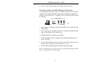
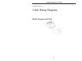
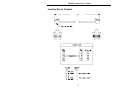
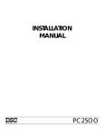
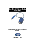
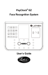
PC100 Terminal
Installation &
User’s Guide
PayClock, Lathem and the Lathem logo are registered trademarks of Lathem Time Corporation. Other product names mentioned in
this manual may be trademarks of their respective companies and are hereby acknowledged.
Warning: Changes or modifications to this unit not expressly approved by the party responsible for compliance could void the user’s
authority to operate the equipment.
NOTICE: This equipment has been tested and found to comply with the limits for a Class A digital device, pursuant to Part 15
of the FCC Rules. These limits are designed to provide reasonable protection against harmful interference when the equipment is
operated in a commercial environment. This equipment generates, uses, and can radiate radio frequency energy and, if not installed
and used in accordance with the instructional manual, may cause harmful interference to radio communications. Operation of this
equipment in a residential area is likely to cause harmful interference in which case the user will be required to correct the interference
at his or her own expense.
Shielded cables must be used with this unit to ensure compliance with the Class A FCC limits
Limited One-Year Limited Warranty
Lathem warrants the hardware products described in this guide against defects in material and workmanship for a
period of one year from date of original purchase from Lathem or from an authorized Lathem reseller. The conditions
of this warranty and the extent of the responsibility of Lathem Time Corporation (“Lathem”) under this warranty are
listed below.
1.
2.
3.
4.
5.
6.
7.
8.
9.
This warranty will become void when service performed by anyone other than an approved Lathem warranty
service dealer results in damage to the product.
This warranty does not apply to any product which has been subject to abuse, neglect, or accident, or which has
had the serial number altered or removed, or which has been connected, installed, adjusted, or repaired other
than in accordance with instructions furnished by Lathem.
This warranty does not cover dealer labor cost for removing and reinstalling the machine for repair, or any
expendable parts that are readily replaced due to normal use.
The sole responsibility of Lathem under this warranty shall be limited to repair of this product, or replacement
thereof, at the sole discretion of Lathem.
If it becomes necessary to send the product or any defective part to Lathem or any authorized service dealer,
the product must be shipped in its original carton or equivalent, fully insured with shipping charges prepaid.
Lathem will not assume any responsibility for any loss or damage incurred in shipping.
WARRANTY DISCLAIMER AND LIMITATION OF LIABILITY: Except only the limited express warranty
set forth above, the products are sold with no expressed or implied warranties of any kind, and the implied
warranties of merchantability and fitness for a particular purpose are hereby expressly disclaimed. No
warranties are given with respect to products purchased other than from Lathem or an authorized Lathem
reseller and any such products are purchased "as is, with all faults." In no event will Lathem be liable for any
direct, indirect, special, incidental or consequential damages arising out of or in connection with the delivery,
use or inability to use, or performance of this product. In the event any limited remedy given herein shall be
deemed to have failed of its essential purpose, Lathem's maximum liability shall be to refund the purchase price
upon return of the product.
Proof of date of purchase from Lathem or an authorized Lathem reseller is required for warranty service on this
product.
This Warranty grants specific legal rights. Additional legal rights, which may vary by locale, may also apply.
Should any difficulties arise with the performance of this product during warranty, or with any Lathem
authorized service centers, contact Lathem Time at the address below.
Lathem Time
200 Selig Drive, SW, Atlanta, GA 30336
404-691-0405
www.lathem.com
Copyright © 2003 Lathem Time Corporation. All rights reserved.
Document number: USG0038C
08-04-2006
Contents
Welcome
1
Mounting the PC100
2
Connecting to the Computer
4
Connecting the PayClock via RS-232 ..................................................................................................... 4
Connecting Terminals via RS-485........................................................................................................... 4
Connecting Terminals via RS-485 (Star Configuration) ......................................................................... 5
Connecting Terminals via RS-485 (Multi-Drop Configuration) ............................................................. 6
Using the PC100
7
Special Badges......................................................................................................................................... 7
Badge #251 – View Clock Status...................................................................................................... 7
Badge #253 – Set Baud Rate ............................................................................................................ 8
Badge #254 – Setup Terminal ID ..................................................................................................... 8
Specifications........................................................................................................................................... 9
Cable Wiring Diagrams
10
RS-232 (Computer to PC100) ............................................................................................................... 10
RS-485 Multi-Drop................................................................................................................................ 11
Junction Box to Terminal ...................................................................................................................... 12
Troubleshooting
13
PC100 .................................................................................................................................................... 13
PC100 Terminal User’s Guide
CHAPTER 1
Welcome
Reliability, functionality and ease of use are trademarks of the PayClock terminal.
With the PC100 terminal, employees use their plastic ID badges to punch in and out –
it’s that simple. Using Lathem software and your computer, the PayClock terminal is
the perfect solution for businesses that want to track employee time and automate
payroll.
The PC100 terminal package includes the following:
• PC100 Terminal
• AC Wall Adapter – 115 VAC 60 HZ
• Mounting Bracket
• 3 Mounting Screws and Anchors
2 Keys
1
PC100 Terminal User’s Guide
CHAPTER 2
Mounting the PC100
Check your package contents to make sure everything is accounted for before
starting. Decide where to mount your clock. Keep in mind that the AC adapter
plugs into a wall outlet.
To mount the clock, you need the following items:
Drill with a 5/16” bit
Hammer
Phillips head screwdriver
Pencil
1. Screw the mounting bracket to the wall
»
Hold the bracket against the wall so the
top (arrow pointing Up) is 54 inches from
the floor
»
Mark the 3 holes with a pencil
»
Remove the bracket and drill a 5/16-inch
hole at each mark
»
Insert an anchor into each hole, tapping it
with a hammer until it is flush against the
wall
»
Align the mounting bracket back on the wall
»
Insert each screw through the bracket into the anchors, and tighten
securely
2
PC100 Terminal User’s Guide
2. Place the clock onto the mounting bracket
»
Turn your key counter-clockwise in the lock at the clock’s right-middle
section to unlock
»
Align the keyholes on the back of the clock with the studs on the
mounting bracket
»
Slide the clock down onto the bracket
»
Turn the key clockwise to lock the clock onto the bracket
»
Remove the key
3
PC100 Terminal User’s Guide
CHAPTER 3
Connecting to the Computer
After mounting your PayClock on the wall, you need to connect it to your
computer. You can connect the PayClock terminal to the computer using an
RS-232 cable or RS-485 cable. Choose the setup that best suits your needs.
Connecting the PayClock via RS-232
1. Turn the PayClock so its back faces you
2. Plug the power cord (AC adapter) into the PayClock, keeping the cord
slack
3. Plug the other end of the power cord into a wall outlet
4. Connect the jack end of the serial cable to the PC100
5. Connect the other end of the serial cable to an open COM port on your
computer. All serial ports are raised pin (male) connectors
Connecting Terminals via RS-485
When selecting your installation method, the type of wire that will be used is
important. Silver Satin (Modular) cable can be used for short distances less
than 100’ to achieve communications. Category-3 or Category-5 cable with
twisted pairs should be used for distances greater than 100’, in installations
using J-Kits or in areas where the cable may run near a device that transmits
an RF frequency. Do not use J-Kits with modular wire
For details, see the Cable Wiring Diagrams appendix.
The Swift-485+ allows you to connect PayClock terminals to the modular
ports and to the screw terminal blocks. You can use either of the screw
terminal blocks to connect the PC2000, PC100-R or PC3500 terminals. The
PC100 / PC2000 modular port is set up to use with the PC2000 and PC100-R
terminals. The PC2500 modular port is set up to use with the PC400 terminals
(not currently available). The RS232 connection to the PC is made simple
using a stereo type plug in jack.
4
PC100 Terminal User’s Guide
Use either
connection
RS485
Power
to terminals
+
~
~
RJ11 RJ45
PC100
PC2000
PC2500
RS485
RS485
~
~
+
-
POWER
LED’s
RS232
RS232
to PC
Use either
connection
Power to
terminals
RS485
SWIFT-485 plus
Connecting Terminals via RS-485 (Star Configuration)
A star network connects up to 31 terminals or sync time devices to the
computer. You can wire the terminals directly to the SWIFT-485+ or use Jkits (junction boxes). Terminals can be located up to 4000 feet from the
computer
SWI
SWIFT-485+
1. Run Category 3 (minimum) cable from the SWIFT-485+ to a terminal or
J-kit. If you connect directly to a terminal, use an RJ-45 or RJ-11
connector on the end that plugs into the terminal
2. Connect the AC power cord adapter to each terminal and plug the cord
into a wall outlet
3. Repeat these steps for each terminal in the network
5
PC100 Terminal User’s Guide
4. See the Cable Wiring Diagrams for detailed connection points
Connecting Terminals via RS-485 (Multi-Drop Configuration)
A multi-drop network connects up to 31 terminals or sync time devices to the
computer. You wire the terminals to junction boxes running in a single line
starting from the SWIFT-485+. Terminals can be located up to 4000 feet from
the computer
Up to 31 Terminals
Max 4000 ft from SWIFT-485+ to Last Terminal
SWIFT-485+
J-Kit (junction box)
1. Run Category 3 (minimum) cable from the SWIFT-485+ to the first J-Kit
(junction box)
2. Use a cable (up to 4 feet long) with an RJ-11 connector on both ends, and
plug one end into the J-Kit (junction box)
3. Plug the other RJ-11 connector to a terminal
4. Connect the power cord (AC adapter) to the terminal and plug the cord
into a wall outlet
5. For the next terminal, run cable from the previous J-Kit (junction box) to
the next J-Kit (junction box) and repeat steps 2, 3 & 4
6. See the Cable Wiring Diagrams for detailed connection points
For more details or how to supply AC power to the PC100-R from the SWIFT485+, see the SWIFT-485+ User’s Guide.
6
PC100 Terminal User’s Guide
CHAPTER 4
Using the PC100
The base model PC100 clock allows only an RS-232 connection. The PC100-R
model allows RS-232 or RS-485 connections; RS-485 connections require the
Terminal Manager software add-on.
The PC100 has a magnetic stripe badge reader. The magnetic stripe should be on
the left side of the badge when swiping. To swipe the badge, insert it at the top of
the reader, and then pull it down with a continuous and smooth motion.
Special Badges
Three supervisor badges are available for your PC100. These badges perform
certain tasks at the clock.
Badge #251 – View Clock Status
This badge displays a clock status report. The status report shows the current
clock setup:
7
VER 1.05 | CLK READY
ID# 049 | BAUD 9600
MEM 10% | TIME 12HR
| DST
ON
PC100 Terminal User’s Guide
♦ PC100 version number
♦ Terminal ID# (ID=49)
♦ Percent full memory
(each time you poll the clock, this resets to 0%)
♦ Clock ready status (READY/LOAD LIST)
♦ Baud Rate
♦ 12-Hour or 24-Hour time display format
♦ Daylight Savings Time (DST) ON/OFF
After a few seconds, the display returns to normal.
Badge #253 – Set Baud Rate
Swipe this badge to change the baud rate – the default is 9600. You may need
to reduce the baud rate if you have
ENTER BAUD 1ST DIGIT
problems communicating with the clock.
These problems can result from a noisy
1200 2400 4800 9600
environment or a long serial cable
(usually more than 50 feet).
To change the baud rate, swipe the Set Baud Rate badge, then when
prompted, swipe employee badge #1, 2, 4 or 9 to indicate 1200, 2400,
4800 or 9600 baud.
NOTE: RS-485 communications do not support 1200 baud
Badge #254 – Setup Terminal ID
Swipe this badge to change the clock ID – the default ID is 49. When
prompted, swipe an employee badge that matches your desired ID. If you
have more than one clock, make sure each one has a unique ID number.
8
PC100 Terminal User’s Guide
Specifications
Casing:
6.375”W x 7.375”H x 1.5”D flame-retardant ABS plastic. 19 oz.
Includes key lock and wall mounting bracket
Power:
6VDC/ 300 mA wall-mount power supply. UL approved
Display:
4 lines x 20 characters liquid crystal with large block digits
Swipe
Status:
“Beeper” signals good or bad badge reading and low memory.
Green and red LED’s show good or bad badge swipes
Badge
Reader:
Mag-Stripe Track 2 reads standard “credit card” format
Badges:
Accepts badges #1-250. Badge metallic stripes are even-parity
Memory:
Stores about 1,500 registrations. Protected by internal 10-year
lithium battery.
This product’s lithium battery contains Perchlorate Material –
special handling may apply. Please go to web site
www.dtsc.ca.gov/hazardouswaste/perchlorate for information
about proper methods of disposal in California.
Ports:
RS-232 cable at speeds of 1200, 2400, 4800 and 9600 baud
For PC100-R: RS-485 Cat. 3 or Cat. 5 cable (suggested) at speeds
of 2400, 4800 and 9600 baud. Up to 4000 feet
Certifications: UL; C-UL; FCC Part-15 Class-B; Canada ICES-003 Class-B;
CE-CENELEC EN55022; CENELEC EN55024
9
PC100 Terminal User’s Guide
APPENDIX A
Cable Wiring Diagrams
RS-232 (Computer to PC100)
10
PC100 Terminal User’s Guide
RS-485 Multi-Drop
PayClock
PayClock
See Fig. A
Be sure to maintain polarity through out the chain
Fig. A – Junction box wiring connect points
Some junction boxes have
only six connect points
instead of eight
8 points
6 points
11
PayClock
PC100 Terminal User’s Guide
Junction Box to Terminal
12
PC100 Terminal User’s Guide
APPENDIX B
Troubleshooting
PC100
Description
When I swipe a badge, it does not
record and the clock does not signal
any errors
Solution
Make sure you swiped the badge
correctly. See the section on Using the
PC100
Or
This badge may have been exposed to
something magnetic. Replace this
badge with a new one
13
PC100 Terminal User’s Guide
INDEX
B
S
Badges................................................... 7
Baud Rate.............................................. 8
Bracket .............................. See Mounting
Bus Configuration................................. 6
Cable ..................................................... 4
Screws ............................... See Mounting
Special Badges ...................................... 7
Specifications
PC100 ................................................ 9
Star Configuration................................. 5
Supervisor Badges ................................ 7
Sync Time Devices ............................... 9
J
T
Junction Box ....................................... 12
Terminal Connections........................... 4
Terminal ID........................................... 8
T-Junction Box ................................... 12
Troubleshooting
PC100 .............................................. 13
C
M
Modem .................................................. 4
Mounting............................................... 1
PC100 ................................................ 2
Multi-Drop Configuration..................... 6
V
P
View Clock Status ................................ 7
PC100............................................ 1, 7, 9
PC2000.................................................. 4
Punch the Clock .................................... 1
W
R
RS-232 ............................................ 4, 10
RS-485 .................................................. 4
Wiring Diagrams................................. 10