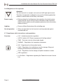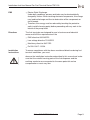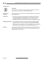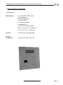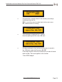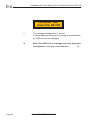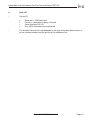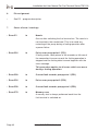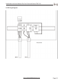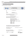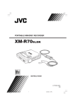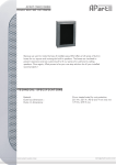
1
Installation And User Manual For Fuel Terminal Series TDE 100
Installation and user manual
Fuel terminal series TDE 100
Responsable for the contents:
K + S ELEKTRONIK GmbH
Eichendorffstr. 31
D-78054 VS-Schwenningen
Phone: +49 (0) 77 20 - 96788-20
Fax: +49 (0) 77 20 - 96788-66
[email protected]
www.k-s-elektronik.de
This documentation is protected by copyright. Neither the manual in full nor any part of
it may be extended, reproduced nor modified without the explicit written approval of
K+S ELEKTRONIK GmbH.
Development: Version 06.02.2009
© K + S ELEKTRONIK GmbH
© Copyright
Installation And User Manual For Fuel Terminal Series TDE 100
1. Contents
2. Introduction
2.1
For the user
2.2
Safety instructions
2.3
Safety symbols
2.4
Additional important symbols at the fueling station site
2.5
Basic safety instructions
2.6
Obligations of the operator
2.7
Compliance with instructions and regulations
2.8
Warranty
4
4
5
6
7
7
8
8
10
3. General product information
3.1
Overview
3.2
Scope of performance of the hardware
3.2.1 Construction
3.2.2 Functional description
11
11
12
12
13
4. Operating mode
4.1
Prior to initial commissioning
4.1.1 Visual check
4.2
Commissioning
4.2.1 Memory test
4.2.2 Fueling operation
4.2.3 Error messages during the fueling operation
14
14
14
14
15
16
18
5. Service mode
5.1
Short description of the parameters and their functions
5.2
Creation of a new badge
5.3
Locking/modifying badges
5.4
Data transmission
5.5
Quantity display
5.6
Settings regarding the fuel type table
5.7
USB query process badges
5.8
USB query process fueling data
5.9
USB query process parameters
19
19
24
26
30
31
31
31
34
37
© K + S ELEKTRONIK GmbH
Page 1
Installation And User Manual For Fuel Terminal Series TDE 100
6. Data call
6.1
PIN assignment
41
42
7. Cases of error / warnings
42
8. Electric installation
8.1
PIN assignment
8.2
Wiring diagram
43
43
45
9. Test certificates and other certificates
9.1
EC declaration of conformity
9.2
QMS certificate
46
46
47
Page 2
© K + S ELEKTRONIK GmbH
Installation And User Manual For Fuel Terminal Series TDE 100
© K + S ELEKTRONIK GmbH
Page 3
Installation And User Manual For Fuel Terminal Series TDE 100
2. Introduction
2.1 For the user
About this
manual
This installation and user manual serves for providing the user with the
necessary information and instructions facilitating complete and
effective installation, parameter setting, operation and maintenance of
the fuel terminal series TDE 100. Therefore, read the corresponding
chapters prior to proceeding with the installation or operation of the fuel
terminal.
This manual has been carefully worked out by the manufacturer and is
an integral part of any fuel terminal delivery according to the
CE directive.
The manual is arranged in individual topic-related chapters and sections
and has a logical structure (learn - prepare - use - maintain).
The manual and any attached documents must be kept in a safe place
within reach during the whole service life of the fuel dispenser. Thus, it
also constitutes an information source for operation settings and error
elimination with regard to the fuel terminal.
This manual reflects the technical state-of-the-art at the date of fuel terminal sale or delivery.
This manual is subject to modifications and updates resulting from further developments.
Intended
use
The fuel terminals of the TDE 50 /100 series are only disigned for use in
company-based fueling stations as the fuel terminals are not certified.
This is why the fuel terminal cannot be used for settlement/billing
operations towards third parties.
Page 4
© K + S ELEKTRONIK GmbH
Installation And User Manual For Fuel Terminal Series TDE 100
2.2 Safety instructions
General
The user is liable for the observance of the contents of this manual. Any
use contrary to the designated use described in this manual is not
permitted. The user is solely responsible for any damage resulting from
such use.
The safety instructions are not only intended for assuring the own safety
but also for the protection of persons not involved against damage to
property and body. Safe operation of the fuel terminal is hereby garanteed.
The symbol shown (left-hand side) is used in this installation and user
manual in order to draw special attention to important information and
remarks.
© K + S ELEKTRONIK GmbH
Page 5
Installation And User Manual For Fuel Terminal Series TDE 100
2.3 Safety symbols
The following symbols draw the attention to important special notes.
Attention!
This pictogram draws attention to legal regulations which must be complied with regarding assembly, commissioning and use of fuel terminals.
Warning!
Non-observance of these requirements can lead to injury of
persons and/or damage to the fuel terminal.
Caution - electric voltage!
Warning against touching electric lines and contacts. Non-observance
of these requirements can cause electric shock and lead to injury of
persons and damage to property.
Explosion hazard!
Special care is required in the case of spilled fuel. Inflammable vapours
may easily lead to explosion or deflagration. Therefore, such fuel must be
removed immediately by means of suitable absorbent means.
Electrostatically endangered components, ESD!
This means that any contact with the contact surfaces or electr.
components may lead to the destruction of the electronic control unit
and put the fuel terminal out of service.
Page 6
© K + S ELEKTRONIK GmbH
Installation And User Manual For Fuel Terminal Series TDE 100
2.4 Additional important symbols at the fuelling station site
Explosion hazard
No smoking
No mobile phones
No open fire
The “No mobile phones” sign is especially important if one uses the
mobile phone while refuelling motor gasoline at the same time.
Deflagration may occur when activating the buttons.
2.5 Basic safety instructions
Protection and
safety devices
Any protection and safety devices must be checked regularly, but at the
latest when carrying our maintenance work.
They may never be bypassed or ignored.
Any removed safety and proection devices must be:
mounted again before putting into operation
checked for correct functioning.
Make sure that the safety devices at the installation site
(e.g. Emergency Stop button, fire fighting devices) are visible and
easily accessible.
© K + S ELEKTRONIK GmbH
Page 7
Installation And User Manual For Fuel Terminal Series TDE 100
2.6 Obligations of the operator
Attention!
The fuel terminal is a complex unit and must fulfill high requirements.
Therefore, the operator is obliged to carry out the following protection
measures and to observe the safety instructions.
Power supply
Before putting the fuel dispenser into operation, the electric power
supply and the correct wiring must be checked in order to prevent
electric shocks and to ensure explosion protection (fuels are combustibles of class I).
Lighting
Ensure sufficient illumination of the refuelling area.
Out of operation
When not operated, the fuel terminal must be protected against
unauthorized use.
2.7 Compliance with instructions and regulations
Overview
UVV - Accident prevention regulation
VdTÜV bulletin 651 “Electric equipment of fuelling stations”
TRbF - Technical rules for inflammable liquids
GefStoffV - Regulations for hazardous substances
VbF - Regulations for inflammable liquids
VAwS - Regulations for installations used for storage, filling and
handling of substances hazardous to water
VLwF - Regulations for the storage of liquids hazardous to water
VDE regulations
21. BimSchV - Regulations regarding the Federal Immission Control
Law
Page 8
© K + S ELEKTRONIK GmbH
Installation And User Manual For Fuel Terminal Series TDE 100
ESD
Directives
Electro Static Discharge.
Under daily conditions, persons and tools may be electrostatically
charged by friction. When touching electronic components, this charge
may lead to discharge and thus to destruction of the components or
circuit boards.
Therefore, this energy must be reduced by touching the protective
earth (metallic housing parts) before proceeding with any work in the
interior of the pump head.
The fuel terminals are designed for use in business and industrial
areas and fulfill the requirements of the
EMC directive 89/336/EEC
Low-voltage directive 73/23/EEC
Machinery directive 98/37/EC
En DIN 13617-1:2004
Installation
instructions
To ensure compliance with the above mentioned directives during fuel
terminal installation, you must:
observe the installation instructions described in this manual and make
sure that the metallic housing parts of the fuel dispenser and the
earthing conductor are connected to the same potential and no
compensation current may flow.
© K + S ELEKTRONIK GmbH
Page 9
Installation And User Manual For Fuel Terminal Series TDE 100
2.8 Warranty
Important!
The company K + S grants a warranty for the fuel terminal within the
scope of the “General Terms and Conditions (AGB)”.
Exclusion of
warranty
Warranty claims are void if one of the following points is not observed
and complied with:
Personnel
Any work as well as any interventions on the electronics of the fuel
terminal require special knowledge and may only be carried out by
authorized companies. The company K + S is not liable for any
damage resulting from incorrect maintenance or incorrect intervention.
Original spare parts
Any modifications of the fuel terminal carried out without the explicit
approval of the manufacturer lead to the exclusion of all liability
claims towards the manufacturer. This also applies to the use of spare
parts which are not produced or released by the company K + S.
Delivery
Page 10
The correct functioning, safety and accuracy of each fuel terminal are
checked in the factory. The fuel terminal is delivered together with the
required approval certificates.
© K + S ELEKTRONIK GmbH
Installation And User Manual For Fuel Terminal Series TDE 100
3. General product information
3.1 Overview
Manufacturer
K + S ELEKTRONIK GmbH
Fuel dispensers
System engineering
Pump electronics
Fuel data acquisition
Eichendorffstr. 31
D-78054 VS-Schwenningen
Phone: +49 (0) 77 20 - 96788-20
Fax: +49 (0) 77 20 - 96788-66
Product
Fuel terminal, not calibratable.
Product
designation
Fuel terminal series TDE 100
© K + S ELEKTRONIK GmbH
Page 11
Installation And User Manual For Fuel Terminal Series TDE 100
3.2
Scope of performance of the hardware
The hardware of the fuel terminal TDE 100 only includes the minimum required
routines needed for the realization of a low-cost fuel terminal which is mainly intended for
the integration into a fuel dispenser. This fuel terminal is of course also available as a
stand-alone version or as a wall mounted unit. The non-calibratable version of the fuel
terminal TDE 100 is only designed for use in company-based filling stations.
3.2.1
Construction
Built-in model:
Front panel made of stainless steel, stainless
steel keypad comprising 12 keys, LCD display 2 x16 digits,
character height 10 mm with backlight illumination enabling easy
reading and with transponder antenna for reading simple
transponder tags. The back of the unit consists of a steel panel
housing. Except for the power supply unit and the motor
contactor, all components required for operation are located in the
inside of the fuel terminal housing.
Wall mounted unit: High-quality metal housing made of zincor, material thickness
1.5 mm with powder coating.
Stand-alone model: High-quality metal housing made of zincor, material thickness
1.5 mm with powder coating. The front panel can be locked by
means of a cylinder lock.
3.2.2
Technical specifications
It is possible to serve one pump using any possible version:
e.g. large-volume/small-volume dispensing with one or two hydraulic units,
two encoders. High-performance dispensing via one or a double hydraulic
system.
Page 12
© K + S ELEKTRONIK GmbH
Installation And User Manual For Fuel Terminal Series TDE 100
The fuel terminal has a flexibly partitioned memory area. During the initial
commissioning, you can determine the maximum number of badges to be
managed (50, 100, 200, 400). The number of fueling operations to be recorded
(2000,1900, 1800, 1600) results from this setting. In the standard configuration,
the memory of the fuel terminal is configured to 400 badges and 1600 fueling
operations.
Driver-specific as well as vehicle-specific badges can be used. (A, B and A + B
operation) each one with or without PIN. Two 16-byte text fields enabling
various input options are allocated to each badge. The fuel data can be called
via PC (simple PC evaluation program, alternatively also the product Autopoll).
The PIN number, date, time, type of fuel and quantity are recorded. Optionally,
the km reading and the vehicle number can also be recorded. An integrated
evaluation is also planned. Evaluation via the display is also possible using the
data relating to the date, time, driver and vehicle. However, in this case the
installation of a printer (option) would be useful.
© K + S ELEKTRONIK GmbH
Page 13
Installation And User Manual For Fuel Terminal Series TDE 100
4.
4.1
Operating mode
Prior to initial commissioning
►
Make sure that the initial commissioning of the fuel terminal is carried out
only by trained and specialized personnel
◄
4.1.1
Visual check
The tight seat of all screw connections or fastenings must be checked.
The cables must be checked for cable break, abrasion signs and cracks. The
individual pins must be checked for correct functioning or damage which may
have been caused during tranport.
The hardware must be checked for loose parts which may affect the operation.
Pay attention to the connection conditions of the DIN profile rail
(terminals L1, N.PE).
The tight seat of plug connections must be checked.
4.2
Commissioning
Check the switch settings of the fuel terminal
Emergency mode switch
ON / OFF » OFF
Switch set to - ON » bridges the fuel terminal » continuous operation
Switch the fuel terminal on 230 VAC 50 HZ
The fuel terminal is already preinialized when it is delivered. Preinitialization with
operator transponder
An operator badge and a customber badge are already configured
Page 14
Operator transponder
PIN: 9999
Name: Operator
Customer transponder
PIN: 0001
Name: Test
© K + S ELEKTRONIK GmbH
Installation And User Manual For Fuel Terminal Series TDE 100
Switch the fuel terminal on 230 VAC 50 HZ
The following message appears on the display
TDE_100
V40.11
Fuel terminal designation and software version number
Duration of displaying: 3 seconds
4.2.1
Memory test
The plausibility of the contents of all memories is checked
Speichertest
0123456789
0
1,2
3,4,5,6,7,8,9
Correctness of the parameters
Correctness of the badge data
Correctness of the fuel data records
Duration of displaying: 3 seconds
© K + S ELEKTRONIK GmbH
Page 15
Installation And User Manual For Fuel Terminal Series TDE 100
Once the memory test has been sucessfully completed, the fuel terminal is again
in the operating mode and expects the presentation of a transponder in front of
the reading point.
Transponder ?
4.2.2
Fueling operation
•
Request to present the transponder in front of the reading point
»
Customer transponder
Presentation of an operator transponder
»
The fuel terminal changes from the operating mode to the
service mode
•
Reading-in of the transponder data
*******************
»
Page 16
Then the fuel terminal searches the memory for this badge and
saves the data in the working memory. Depending on the badge
data read in, the next input prompt follows. Generally, the request to
enter the PIN number then follows.
© K + S ELEKTRONIK GmbH
Installation And User Manual For Fuel Terminal Series TDE 100
•
Enter the PIN number via the keypad
PIN ??
Esc
0000
OK
PIN number not correct
»
new input request
This procedure can be repeated up to three times. However, if the PIN number
entry is still not correct after the third trial, the program is canceled and the fuel
terminal is reset to the initial setting.
•
PIN number correct
»
next prompt
If no further input requests, such as the entry of the vehicle number or
km reading, are defined in the badge, the fueling operation starts.
•
Request to remove the nozzle, if it has not yet been removed
ZV ziehen
© K + S ELEKTRONIK GmbH
Page 17
Installation And User Manual For Fuel Terminal Series TDE 100
•
The pump is switched on and the pumping operation starts
Abgabe:____0,00 Ltr.
The flow meter or the piston meter supplies the necessary counting pulses for
the CPU and the display via the encoder. This procedure stops when the noozle
is put into place again or the allowed quantity has been reached. In this case, the
pump motor is switched off and the data of this fueling operation is permanently
saved in the fuel operation memory.
•
If no fueling operation follows, the dispensed quantity is displayed during the time
defined in parameter 35.
•
The maximum fueling time is defined in seconds in the parameter 36. At the end
of the set time, the fueling operation is terminated and saved.
►
The maximum admissible fueling time is normally specified by the fire
protection, safety or environmental authorities. If the specified value is not
known, please contact the competent water protection authority.
◄
4.2.3
Error messages during the fueling operation
•
In case of error, the fueling operation is terminated and the data is saved with the
correspoonding error code. The error is displayed in clear text on the display.
Abgabe:____0,00 Ltr.
E81 Impulsgeber
»»»
Page 18
To continue, the fuel terminal must be switched off and on
© K + S ELEKTRONIK GmbH
Installation And User Manual For Fuel Terminal Series TDE 100
5.
Service mode
►
5.1
There are two possiblities to access the service mode:
A)
Via the operation / service switch
»
»
Service/Operation switch
set to position : Service
Calibration On/Off
set to position: On
( If parameters are to be modified or a new badge is to be created)
B)
Via the operator badge with the PIN number 9999
Short description of the parameters and their functions
SERV. PARAM.NR.
___ OK
Esc
»
»
»
________ = Input of numbers
OK
= OK
Esc
= Delete
• Parameter 01
►
Status / check instruction
• Parameter 02
►
TDE 100 V40.11
Unit designation and program version, only displayed.
The display switches back to the basic menu after
3 seconds
• Parameter 03
►
Checksum : xxxx
Only displayed. Switches back to the basic menu after
3 seconds
© K + S ELEKTRONIK GmbH
Page 19
Installation And User Manual For Fuel Terminal Series TDE 100
• Parameter 04
►
Address 1
Only displayed. Switches back to the basic menu after
3 seconds
• Parameter 05
►
Format badge memory
• Parameter 06
►
Format badge memory
• Parameter 07
►
Not used
• Parameter 08
►
Not used
• Parameter 09
►
Not used
• Parameter 10
►
Not used
• Parameter 11
►
Quantity in liters
The current value of the last fueling operation (quantity)
is displayed or can be requested, also possible during
the fueling operation (online monitoring)
• Parameter 12
►
Pulse value pump point 1 (ZP1)
• Parameter 13
►
Pulse value pump point 2 (ZP2)
• Parameter 14
►
Not used
• Parameter 15
►
Not used
• Parameter 16
►
Not used
• Parameter 17
►
Not used
• Parameter 18
►
Not used
• Parameter 19
►
Not used
• Parameter 20
►
Not used
Page 20
© K + S ELEKTRONIK GmbH
Installation And User Manual For Fuel Terminal Series TDE 100
• Parameter 20
►
Not used
• Parameter 21
►
Date
Display format JJ:MM:DD can be modified and
accepted with OK , or deleted with Esc in case of
incorrect entries.
• Parameter 22
►
Clock
Display format HH:MM:SS can be modified and
accepted with OK , or deleted with Esc in case of
incorrect entries.
• Parameter 23
►
Not used
• Parameter 24
►
Not used
TDE 100
pulse correction factor:
5.0000 and 0.0001 standard: 0,0100
For two-channel encoder 1 to 250 pulses per liter
© K + S ELEKTRONIK GmbH
Page 21
Installation And User Manual For Fuel Terminal Series TDE 100
• Parameter 25
►
See “Reading USB badges”
• Parameter 26
►
See “Reading USB fueling data”
• Parameter 27
►
See “Reading USB parameters”
• Parameter 28
►
Not used
• Parameter 29
►
Not used
• Parameter 30
►
Total pump point 1 + 2 (ZP1 + ZP2)
• Parameter 31
►
Current check encoder On / Off
Monitoring of the encoder 0 = without current check
1 = with current check. The current check should display
the error E 81 when falling below the value of 10 mA
(cable break) and when exceeding the value of 80 mA
(short circuit).
• Parameter 32
►
Km reading
• Parameter 33
►
Total fuel stock
Quantity determined by calculation in the reservoir.
• Parameter 34
►
Filling of the tank - filling quantity
Must be entered manually after filling the reservoir. This
quantity is added to the old fuel stock (P33).
Page 22
© K + S ELEKTRONIK GmbH
Installation And User Manual For Fuel Terminal Series TDE 100
• Parameter 35
►
Displaying time in seconds
Time in seconds during which the dispensed quantity is
shown on the display after completion of the fueling
operation.
• Parameter 36
►
Fueling time in seconds
Maximum fueling time in seconds.
• Parameter 37
►
Pre-flow suppression on the display
Number of pulses not displayed after starting the fueling
operation. This prevents the counting of hose inflations.
• Parameter 38
►
Zero-fueling counter
As a defective encoder (IG) may cause zero-fuelings, the
zero-fueling monitoring function is used. After each
zero-fueling, this value is reduced by 1 until the value 0 is
reached. Then the fuel terminal is locked.
(Parameter is 00). It can be unlocked again by entering a
new maximum value.
• Parameter 39
►
Max. dispensing value pump point 1 + 2 (ZP1 + ZP2)
© K + S ELEKTRONIK GmbH
Page 23
Installation And User Manual For Fuel Terminal Series TDE 100
5.2
Creation of a new badge
• Parameter 40
►
Creation of a new badge
Serial number of the badge
Transponder ?
» Present the new transponder to the reading point
» The transponder number is displayed
AW.ART 0...6
» Enter the badge type 0 to 6
» Enter a designation for the badge type
► 1 user
► 2 operator
► 3 A/B badge
► 4 vehicle badge (without PIN)
PIN ? 0000
OK
Esc
» Enter the desired PIN
» Key Esc - enables PIN number correction
» Key OK - confirm and create badge
»
»
»
»
Name
Input of km reading
Type
Max. fueling quantity
► The operator badge has the special badge number 9999 ◄
Page 24
© K + S ELEKTRONIK GmbH
Installation And User Manual For Fuel Terminal Series TDE 100
Aufdruck _ _ _ _
OK
Esc
»
Enter and confirm the number or number combination
printed on the transponder
►
The correct assignment of this number and its docu
mentation are very important as, when loosing the
badge, it is only possible to delete and disable the
badge on the terminal by means of this number. In
addition, when a lost badge is found again, this
number is also required to enable (release) the
transponder again.
◄
Firma Nr. _ _
OK
Esc
»
The entry of a 2-digit company number allows you to assign a
clear text to the evaluation in the PC program
Name / Text
»
»
»
Here it is possible to define any text comprising 16 characters.
Generally, this is the name of the user.
Confirm with OK
Back to the main menu
© K + S ELEKTRONIK GmbH
Page 25
Installation And User Manual For Fuel Terminal Series TDE 100
5.3
Locking/modifying badges
• Parameter 41
►
Lock badge
Aufdruck _ _ _ _
Sperren OK Esc
»
Enter and confirm the number printed on the
transponder to be locked
Aufdruck _ _ _ _
Sicher ? OK Esc
»
Confirm with OK
Aufdruck _ _ _ _
Sperren
»
Page 26
The message is displayed during 1 second, then back to
the main menu
© K + S ELEKTRONIK GmbH
Installation And User Manual For Fuel Terminal Series TDE 100
• Parameter 42
►
Lock badge
Aufdruck _ _ _ _
Löschen OK Esc
»
Enter the number printed on the transponder to be deleted
and confirm with OK
»
Correct with ESC in the case of an incorrect entry
»
If you wish to exit the program here, press
→ OK → the program switches to the next query
Aufdruck _ _ _ _
Sicher ? OK Esc
»
ESC → You exit the program, no badge is deleted
»
Continue with OK
Aufdruck _ _ _ _
Löschen
»
Badge is deleted
© K + S ELEKTRONIK GmbH
Page 27
Installation And User Manual For Fuel Terminal Series TDE 100
• Parameter 43
►
Modify badge
Aufdruck _ _ _ _
Freigabe OK Esc
»
Enter the number printed on the transponder to be
released and confirm with OK
Aufdruck _ _ _ _
Sicher ? OK Esc
»
Confirm with OK
Aufdruck _ _ _ _
Freigabe
»
Page 28
The messge is displayed during 1 second, then back to
the main menu
© K + S ELEKTRONIK GmbH
Installation And User Manual For Fuel Terminal Series TDE 100
• Parameter 44
►
►
Nummernerkennung
Badge information
If the number printed on the transponder can no longer be
read/recognized, the number can be enquired using this
service parameter
Transponder ?
»
Show/present the transponder
Aufdruck _ _ _ _
Firma Nr. _ _ _ _ OK
»
Confirm with OK and back to the main menu
© K + S ELEKTRONIK GmbH
Page 29
Installation And User Manual For Fuel Terminal Series TDE 100
• Parameter 45
►
Not used
• Parameter 46
►
Not used
• Parameter 47
►
Not used
• Parameter 48
►
Not used
• Parameter 49
►
Not used
5.4
Data transmission
•
How can the data transmission between the fuel terminal and the PC be
realized?
►
►
►
►
No connection (USB stick)
Direct connection (data line)
Standard modem
Radio modem (GSM)
•
The version to be used depends on the local conditions as well as on the
distance between the fuel terminal and the PC. For example, the max. distance
of 15 m must not be exceeded in the case of direct connection
(without line amplifier).
•
The suitable transmission rate depends on the data transmission method or on
the installed modem and the quality of the telephone line.
Page 30
© K + S ELEKTRONIK GmbH
Installation And User Manual For Fuel Terminal Series TDE 100
5.5
Quantity display
•
For the fuel dispenser, the dispensed liters (or kilograms in case of gas
dispensers) of the internal pump point can be shown on the display of the
integrated fuel terminal during the fueling operation. This means that during the
fueling operation the display shows the quantity continuously.
•
The maximum time in seconds during which this quantity/volume display remains
after putting the nozzle back into place is generally set to 20 seconds.
5.6
Settings regarding the fuel type table
•
Generally, it is possible to define 9 fuel types in the fuel terminal.
To guarantee clear assignment of tank:fuel type:pump point only the fuel types
really used should be defined.
•
The following settings are made for each fuel type in the fuel type table:
►
►
5.7
Assignment of the fuelt ype number to the fuel type designation
Quantity unit of the fuel type (“liter” for liquid fuel types,
“kg” for gases)
USB query process badges
Transponder ?
»
Show/present the operator transponder
© K + S ELEKTRONIK GmbH
Page 31
Installation And User Manual For Fuel Terminal Series TDE 100
SERV. PARAM.NR.
___ OK
Esc
»
►
Plug in the USB stick
Make sure that the USB stick is not dirty, humid or
mechanically deformed. ◄
»
Enter the program number for the USB downloading:
No. 25 for badges
No. 26 for fueling data
No. 27 for parameters
Example - no. 25 for badges
USB-Stick Suche
0378
»
The fuel terminal establishes the contact with the USB
stick. In the second line, the number of attempts required
by the fuel terminal to establish a safe connection. If this
value exceeds 1000, the process is cancelled and the
error message E 60 is issued
USB-Stick Suche
USB - gefunden
»
Page 32
This message is displayed for approximately 1 second
© K + S ELEKTRONIK GmbH
Installation And User Manual For Fuel Terminal Series TDE 100
Ausweise neu
OK
ESC
»
If you wish to read only the new badges, i. e. the badges
generated since the last read-out?
ESC = jump to the next selection
Ok = confirm
The newly generated badges are transferred into the
existing file and added to the file end. If this file is not
changed on the PC, it contains a chronology of all badges.
Ausweise Alle
OK
ESC
All badge records stored in the memory are transferred into the
file. The file is overwritten from the beginning. If the file
contains data records which are older than those stored in the
memory of the fuel terminal, this data is lost. It is
recommended to save a backup copy on the PC.
ESC = to exit the servcice mode, back to the main menu
Ok = data transfer is running
Ausweise Alle
open File: TK.TXT
»
This message is displayed for 1 second.
Note for opening the file in the USB stick
© K + S ELEKTRONIK GmbH
Page 33
Installation And User Manual For Fuel Terminal Series TDE 100
Ausweise Alle
0000 File: TK.TXT
»
All data contained in the fuel terminal memory is saved in
the USB stick under the file name: TK.TXT
A four-digit counter shows the consecutive number of saved
data records. The same applies to the function
“Save NEW badges”
Ausweise Alle
close File: TK.TXT
5.8
»
The message is displayed for 1 second.
A note is displayed telling you that saving is completed and
the USB stick can be unplugged.
►
Note: If the USB stick is unplugged too early during the
saving process, this may cause data loss.
◄
USB query process fueling data
Transponder ?
»
Page 34
Show/present the operator transponder
© K + S ELEKTRONIK GmbH
Installation And User Manual For Fuel Terminal Series TDE 100
SERV. PARAM.NR.
___ OK
Esc
»
►
Plug in the USB stick
Make sure that the USB stick is not dirty, humid or
mechanically deformed. ◄
»
Enter the program number for the USB downloading:
No. 25 for badges
No. 26 for fueling data
No. 27 for parameters
Example - no. 26 for fueling data
USB-Stick Suche
0378
»
The fuel terminal establishes the contact with the USB
stick. In the second line, the number of attempts required
by the fuel terminal to establish a safe connection. If this
value exceeds 1000, the process is cancelled and the
error message E 60 is issued
USB-Stick Suche
USB - gefunden
»
This message is displayed for approximately 1 second
© K + S ELEKTRONIK GmbH
Page 35
Installation And User Manual For Fuel Terminal Series TDE 100
Tankdaten neu
OK
ESC
»
Do you wish to read only the new fueling data generated
since the last read-out?
ESC = jump to the next selection
Ok = confirm
The newly generated fueling data is transferred into the
existing file and added to the file end. If this file is not
changed on the PC, it contains a chronology of all
fueling data.
Tankdaten Alle
OK
ESC
All fueling data records stored in the memory are transferred
into the file. The file is overwritten from the beginning. If the file
contains data records which are older than those stored in the
memory of the fuel terminal, this data is lost. It is
recommended to save a backup copy on the PC.
ESC = to exit the servcice mode, back to the main menu
Ok = data transfer is running
Tankdaten Alle
open File: TK.TXT
»
Page 36
This message is displayed for approximately 1 second.
Note for opening the file in the USB stick
© K + S ELEKTRONIK GmbH
Installation And User Manual For Fuel Terminal Series TDE 100
Tankdaten Alle
0000 File: TK.TXT
»
All data contained in the fuel terminal memory is saved in
the USB stick under the file name: TK.TXT
A four-digit counter shows the consecutive number of saved
data records. The same applies to the function
“Save NEW badges”
Tankdaten Alle
close File: TK.TXT
5.9
»
The message is displayed for 1 second.
A note is displayed telling you that saving is completed and
the USB stick can be unplugged.
►
Note: If the USB stick is unplugged too early during the
saving process, this may cause data loss.
◄
USB query process parameters
Transponder ?
»
Show/present the operator transponder
© K + S ELEKTRONIK GmbH
Page 37
Installation And User Manual For Fuel Terminal Series TDE 100
SERV. PARAM.NR.
___ OK
Esc
»
►
Plug in the USB stick
Make sure that the USB stick is not dirty, humid or
mechanically deformed. ◄
»
Enter the program number for the USB downloading:
No. 25 for badges
No. 26 for fueling data
No. 27 for parameters
Example - no. 27 for parameters
USB-Stick Suche
0378
»
The fuel terminal establishes the contact with the USB
stick. In the second line, the number of attempts required
by the fuel terminal to establish a safe connection. If this
value exceeds 1000, the process is cancelled and the
error message E 60 is issued
USB-Stick Suche
USB - gefunden
»
Page 38
This message is displayed for approximately 1 second
© K + S ELEKTRONIK GmbH
Installation And User Manual For Fuel Terminal Series TDE 100
Parameter Alle
OK
ESC
»
All parameters records stored in the memory are always
transferred into the file.
ESC = to exit the servcie mode, back to the main menu
Ok = data transfer is running
Parameter Alle
open File: PA.TXT
»
This message is displayed for 1 second.
Note for opening the file in the USB stick
Parameter Alle
0000 File: PA.TXT
»
All data contained in the fuel terminal memory is saved in
the USB stick under the file name: PA.TXT
A four-digit counter shows the consecutive number of saved
data records. The same applies to the function
“Save NEW badges”
© K + S ELEKTRONIK GmbH
Page 39
Installation And User Manual For Fuel Terminal Series TDE 100
Parameter Alle
close File: PA.TXT
Page 40
»
The message is displayed for 1 second.
A note is displayed telling you that saving is completed and
the USB stick can be unplugged.
►
Note: If the USB stick is unplugged too early during the
saving process, this may cause data loss.
◄
© K + S ELEKTRONIK GmbH
Installation And User Manual For Fuel Terminal Series TDE 100
6.
Data call
•
Via the PC
>
>
>
>
•
Baud rate = 19200 bd fixed
Format = 8 data bits,no parity,1 stop bit
Serial interface RS 232
Only ASCII characters are transferred
The suitable transmission rate depends on the type of the data transmission or
on the installed modem and the quality of the telephone line.
© K + S ELEKTRONIK GmbH
Page 41
Installation And User Manual For Fuel Terminal Series TDE 100
6.
Pin assignment
•
See PC - program description
7.
Cases of error / warnings
• Error E1
►
Nozzle
Occurs after switching the fuel terminal on. The nozzle is
not inserted in the nozzle boot. This is to avoid any
restarting of the pump during a fueling operation after
a power failure.
• Error E81
►
Pulse error pump point 1 (ZP1)
If faulty pulses, false pulses of the encoder or failures of
the connection line are caused, the fueling operation is
stopped and the fueling data is saved together with the
error message.
This procedure applies to all errors which can occur
during a fueling operation.
• Error E82
►
Current fault encoder pump point 1 (ZP1)
• Error E91
►
Pulse error pump point 2 (ZP2)
• Error E92
►
Current fault encoder pump point 2 (ZP2)
• Error E70
►
Memory error
A memory test is always performed each time the
fuel terminal is switched on.
Page 42
© K + S ELEKTRONIK GmbH
Installation And User Manual For Fuel Terminal Series TDE 100
8.
8.1
Electric installation
PIN assignment
•
X1.1
+24 volt
•
X2.1
Motor 1 normally closed contact
•
X1.2
+24 volt
•
X2.2
Motor 1 change-over contact
•
X1.3
GND
•
X2.3
Motor 1 normally open contact
•
X1.4
GND
•
X2.4
Motor 2 normally closed contact
•
X2.5
Motor 2 change-over contact
•
X3.1
DV2 change-over contact
•
X2.6
Motor 2 normally open contact
•
X3.2
DV2 normally open contact
•
X2.7
AV1 change-over contact
•
X3.3
Reserve output
•
X2.8
AV1 normally open contact
•
X3.4
Reserve output
•
X2.9
DV1 change-over contact
•
X2.10
DV1 normally open contact
•
X2.11
AV2 change-over contact
•
X2.12
AV2 normally open contact
© K + S ELEKTRONIK GmbH
Page 43
Installation And User Manual For Fuel Terminal Series TDE 100
•
X4.1 RS 232 (ser. interface no. 3)
•
X6.1
+5 volt
•
X4.2
RS 232 (ser. interface no. 3)
•
X6.2
RS485A (ser. interface no. 1)
•
X4.3
GND
•
X6.3
RS485B (ser. interface no. 1)
•
X4.4
GND
•
X6.4
GND
•
X7.1
+5 volt
•
X7.2
RS 485 A / RS 232 / 20mA (ser. interface no. 4)
•
X7.3
RS 485 B / RS 232 / 20mA (ser. interface no. 4)
•
X7.4
GND
•
X8.1
+5 Volt
•
X8.2
RS 485 A / RS 232 / 20mA (ser. interface no. 2 )
•
X8.3
RS 485 B /RS 232 / 20mA (ser. interface no. 2 )
•
X8.4
GND
•
X9.1
Enable output 1
•
X10.1
+24 volt
•
X9.2
Enable output 1
•
X10.2
RS232
•
X9.3
Enable output 2
•
X10.3
RS232
•
X9.4
Enable output 2
•
X10.4
GND
•
X11.1 ZV1
•
X11.7
IG2 A
•
X11.2 ZV1
•
X11.8
IG2 B
•
X11.3 ZV2
•
X11.9
+ 5V IG 1
•
X11.4 ZV2
•
X11.10
+ 5V IG 2
•
X11.5 IG1 A
•
X11.11
GND IG1
•
X11.6 IG1 B
•
X11.12
GND IG2
Page 44
© K + S ELEKTRONIK GmbH
Installation And User Manual For Fuel Terminal Series TDE 100
8.2 Wiring diagram
Power
supply
unit
24V
Pump head
© K + S ELEKTRONIK GmbH
Page 45
Installation And User Manual For Fuel Terminal Series TDE 100
9. Test certificates and other certificates
9.1 EC declaration of conformity
EG-Konformitätserklärung
EC - Declaration of Conformity
EC - Declaration de Conformité
Wir
We
Nous
K + S Elektronik GmbH
Anschrift
Address
Eichendorffstr. 31
D-78054 VS-Schwenningen
erklären, dass das Produkt mit der Bezeichnung, Typ, Modell:
declare, that the product with name, type, model:
déclarons, que le produit nom, type, modèle:
Tankautomat Serie TDE 50 / 100
mit den Anforderungen der Normen und Richtlinien
fulfils the requirernents of the standards and regulations of the Directive
satisfait aux exigences des normes et directives
Maschinen-Richtlinie 98/37/EG, 1998
EN 292-1/2 Sicherheit von Maschinen
EN 60204-1 Elektrische Ausrüstung von Maschinen
Niederspannungs Richtlinie 73/23/EWG
EMV-Richtlinie 89/336/EWG
EN 55011 (1998) + A1 (1999) + A2 (2002), Limit Class: B
EN 61000-3-2 (2006-04)
EN 61000-3-3 (1995-01) + A1 (2001-06) + A2 (2005-11)
EN 61000-4-2 (2001)
EN 61000-4-3 (2001)
EN 61000-4-4 (2001)
EN 61000-4-6 (2001)
EN 61000-4-11 (2001)
und den Prüfberichten übereinstimmt und damit den Bestimmungen entspricht.
and the test reports and therefore corresponds to the regulations of the Directive.
et les rapports d'essais et, ainsi, correspond aux règlements de la Directive.
Ort und Datum der Ausstellung:
Place and date of issue:
Lieu et date d'établissement:
VS-Schwenningen, den 28. August 2009
Name und Unterschrift des Befugten:
Name and signature of the authorised persons:
Nom et signature des personnes autorisées:
Page 46
© K + S ELEKTRONIK GmbH
Leitung Entwicklung
Installation And User Manual For Fuel Terminal Series TDE 100
9.2 QMS certificate
© K + S ELEKTRONIK GmbH
Page 47